Yamato GAS410 User manual

Solvent Recovery Unit
GAS410
- First edition -
● Thank you for purchasing “Solvent Recovery Unit GAS410"
of Yamato Scientific Co., Ltd.
● To use this unit properly, read this "Instruction Manual"
thoroughly before using this unit.
Keep this instruction manual around this unit for referring at
anytime.
:WARNING!:
Carefully read and thoroughly understand the important
warning items described in this manual before using this
unit.
Yamato Scientific America Inc.

Contents
1. Safety precautions .................................................................... 1
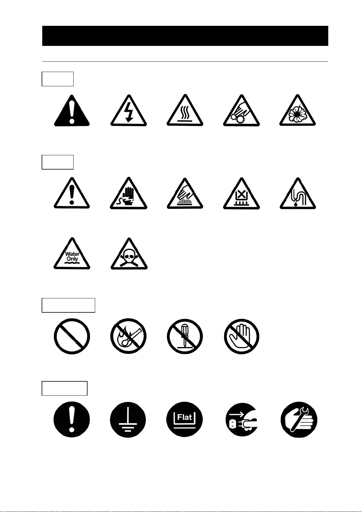
Explanation of pictograms ............................................................. 1
List of symbols ....................................................................... 2
Warning・Cautions ................................................................... 3
2. Before using this unit .................................................................. 5
Precautions when installing the unit ..................................................... 5
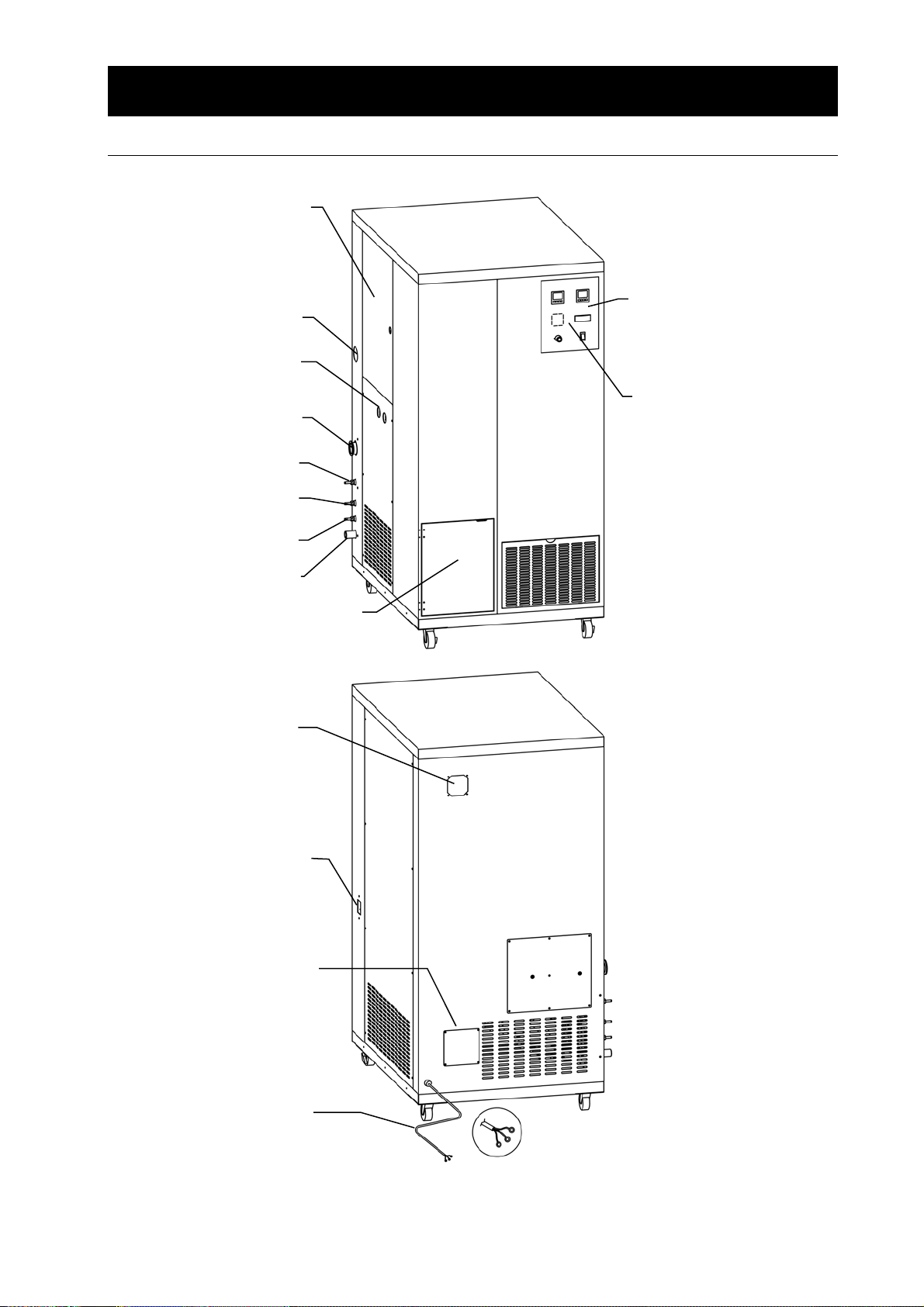
3. Names and functions of parts .......................................................... 8
Main unit ............................................................................ 8
Internal mechanism ................................................................... 9
Operation panel ..................................................................... 10
4. Operating procedures ................................................................ 11
Preparations ........................................................................ 11
Preparations (ADL311S+GAS410) .................................................... 12
Preparations(GB210A+GAS410) .................................................... 14
Operating method ................................................................... 16
Related Figure between Blower and Temperature/Circulating Air Quantity (Reference) ....... 22
5. Handling Precautions ................................................................ 23
About applicable organic solvents ...................................................... 24
Corrosion resistance table ............................................................ 26
Piping system diagram ............................................................... 27
List of materials ..................................................................... 28
Precautions during operation .......................................................... 29
6. Maintenance Method................................................................. 31
Daily Inspection and Maintenance ...................................................... 31
7. Long storage and disposal ............................................................ 34
When not using this unit for long term / When disposing ................................... 34
Matters to consider when disposing of the unit ........................................... 34
8. When a trouble occurs ............................................................... 35
Safety unit and error indications ....................................................... 35
Safety unit and error indications ....................................................... 36
Confirmation and language select for the manual ......................................... 37
Trouble Shooting .................................................................... 39
9. After Service and Warranty ........................................................... 42
When requesting a repair ............................................................. 42
10. Specifications ...................................................................... 43
11. Wiring diagram ..................................................................... 44
12. Replacement parts table ............................................................. 45
13. List of Dangerous Substances ........................................................ 47

1
1. Safety precautions
Explanation of pictograms
About pictograms
A
variety of pictograms are indicated in this operating instruction and on
products for safe operation. Possible results from improper operation
ignoring them are as follows.
Be sure to fully understand the descriptions below before proceeding to the
text.
Warning
Caution Indicates a situation which may result in minor injury (Note 2) and
property damages (Note 3.)
(Note 1)Serious injury means a wound, an electrical shock, a bone fracture or intoxication that ma
y
leave after effects or require hospitalization or outpatient visits for a long time.
(Note 2)Minor injury means a wound or an electrical shock that does not require hospitalization o
r
outpatient visits for a long time.
(Note 3)Property damage means damage to facilities, devices and buildings or other properties.
Meanings of pictograms
This pictogram indicates a matter that encourages the user to adhere to warning
(“caution” included).
Specific description of warning is indicated near this pictogram.
This pictogram indicates prohibitions
Specific prohibition is indicated near this pictogram.
This pictogram indicates matters that the user must perform
Specific instruction is indicated near this pictogram.
Indicates a situation which may result in death or serious injury (Note 1.)

2
1. Safety precautions
List of symbols
Warning
General warnings Danger!: High
voltage
Danger!: High
temperature
Danger!: Moving
part
Danger!: Hazard
of explosion
Caution
General cautions Electrical shock! Burning! Caution for no
liquid heating!
Caution for water
leak!
For water only Poisonous
material
Prohibitions
General bans Fire ban Do not
disassemble Do not touch
Compulsions
General
compulsions
Connect ground
wire Install levelly Pull out the power
plug
Regular
inspection

3
1. Safety precautions
Warning・Cautions
Warning
Do not use this unit in an area where there is flammable or explosive gas
Never use this unit in an area where there is flammable or explosive gas. This unit is not
explosion-proof. Always try to assure sufficient ventilation in the room and take extreme care so
that the atmosphere will not reach the explosive limit concentration. See “13. List of Dangerous
Substances” on P. 47 for explosive or flammable gases.
Always ground this unit
Always ground this unit on the power equipment side in order to avoid electrical shock due to a
power surge.
Apply the source of rated power or more
Be sure to apply the source of rated power or more. Applying non-rated voltage or non-rated
power supply may cause the fire or electric shock.
Prohibition of use for error
If a smoke or abnormal smell may be occurred, turn off the power switch of the main unit
immediately, and turn off the original power source, and finally contact to either the dealer you
purchased this unit or our sales office. Leaving the failure may cause the fire or electric shock.
Since the repairing of this unit is dangerous for non-specified service person, never repair the
unit by the customer himself.
Do not use the power cord if it is bundled or tangled
Do not use the power cord if it is bundled or tangled. If it is used in this manner, it can overheat
and fire may be caused.
Do not damage power cord
Do not damage power cord by bending, pulling, or twisting forcedly. It may cause the fire or
electric shock. Besides, operating the unit with the something put on the cord may cause
overheat, and result in fire.
Never try to touch a hot part.
Some parts of the unit are hot during and immediately after operation. Take special care for
possible burning.
Never try to disassemble or alter the unit.
Never try to disassemble or alter the unit. A malfunction, a fire or an electrical shock may result.

4
1. Safety precautions
Warning・Cautions
Caution
During a thunder storm
During a thunderstorm, turn off the power key immediately, then turn off the circuit breaker and
the main power. If this procedure is not followed, fire or electrical shock may be caused.
If the electric failure shall be occurred,
When power is shut off due to turning the ELB “OFF” or a power failure during GB210A/ADL311S
operation (while the blower is in operation or liquid is being sent), the mode will return to ① or
② after recovery.
① The mode will return to the initial state when the inlet temperature is 60℃ or less or the
outlet temperature is 50℃ or less.
② When the temperature inside the path is high, the unit will continue operation until the inlet
temperature drops to 60℃ or less or the outlet temperature drops to 50℃ or less while
only the blower returns.
Do not perform unattended operation during activating the unit
Do not perform unattended operation during activating the unit. Since the unit is in idling status
and the nozzle is blocked of after the operation using sample, the temperature around outlet is
increased and the remaining sample is flown from the sample tube disconnected from the unit,
and this failure may cause the indeterminism accident.
Any people other than the qualified personnel shall never attempt to
operate the unit.
Take sufficient care for the control of the unit so that any people other than the qualified
personnel shall never have a chance to operate the unit.
Always monitor and check the oxygen concentration.
Always monitor the oxygen concentration in the unit to assure safety.
Take care when opening the unit.
Be sure to confirm that the oxygen concentration has returned to 21% and avoid putting your
face close to the exhaust port carelessly when opening the unit.
Take care for solvents you are going to use.
The unit has been designed to use isopropyl alcohol and ethanol.
Service lives of a filter element or packing may change depending on the type of solvent used.
When leakage of gas or other troubles occurs inside the unit, immediately replace the defective
part with a new one. Check whether a solvent can be used or not in the “About the applicable
solvents” in the section 5. Handling precautions.
Take care for the use of water based solvents.
When you are going to use a water based solvent, remove the GB210A and use ADL311S or
GA310 alone.
See “Restrictions by the melting point” in the section 5. Handling precautions (P.24).

5
2. Before using this unit
Precautions when installing the unit
Warning
1. Always ground this unit
・ Be sure to connect the earth wire (the green cable of power cord) to the grounding
conductor or ground terminal to prevent accidents caused by electric leakage.
・ This unit requires a single phase 220V system power supply (also supports AC200V or
AC240V by selecting either of it) (See page 11 (1)) Ask the nearest electrical contractor
for the power including the connecting work. The setting (connecting) work is performed
following the related electrical equipment technical standard published by the
corresponding country to be used this unit.
・ Do not connect the earth wire to gas or water pipes. If not, fire disaster may be caused.
・ Do not connect the earth wire to the ground for telephone wire or lightning conductor. If
not, fire disaster or electric shock may be caused.
・ The power plug is not attached as
standard component. Connect the
earth correctly adjusting the type of
the power equipment of the user.
2. Pay attention to the color of each core wire when connecting the power cord
Be sure to check that the breaker on the power source
equipment side is turned "OFF" when connecting power cord
without fail. Note that this unit does not attach the power plug as
standard component. Select the appropriate power plug and
terminal matching to the power capacity of the power source
equipment to be connected, and connect them.
Core Wire
Color
In-house
Wiring
Black Voltage Side
White Voltage Side
Green Ground Side
3. Choose a proper place for installation
Do not install this unit in a place where:
Rough or dirty surface.
Flammable gas or corrosive gas is generated.
Ambient temperature bellow 5℃ or above 30C.
Ambient temperature fluctuates violently.
There is direct sunlight.
There is excessive humidity and dust.
There is a constant vibration.
Place where the water is easy-to-be splashed.
Install this unit on a stable place with the space as shown below.
ADL311S
or GB210
A
80cm o
r
more GAS410
50cm or
more
(Rear side)
100cm or
more
(Front side)
50cm or
more
Green (to ground terminal)
Black (to rated power supply terminal)
White (to rated power supply terminal)
Rounded terminal for M4

6
Before using this unit
Precautions when installing the unit
Warning
4. Do not use this unit in an area where there is flammable or explosive gas
Never use this unit in an area where there is flammable or explosive gas. This unit is not
explosion-proof. An arc may be generated when the power switch is turned ON or OFF, and
fire/explosion may result.
Refer to page 47 “13. List of Dangerous Substances”.
5. Do not use explosive or flammable substances
Take extreme care for use of an explosive or a flammable solvent. Such a solvent may cause
an explosion or a fire.
Check whether a solvent can be used or not in the “About the applicable solvents” in the
section 5. Handling precautions (P.24).
Always monitor the oxygen concentration in the unit during operation to assure safety.
Flammable
solvent
Explosive
solvent
Caution
Installation
example
GB210A+GAS410
Explosive gas
Flammable gas

7
2. Before using this unit
Precautions when installing the unit
Warning
6. Do not modify 7. Do not topple or tilt this unit
Modification of this unit is strictly
prohibited. This could cause a failure.
Set this unit to the flattest place. Setting
this unit on rough or slope place could cause
the vibration or noise, or cause the
unrespectable trouble or malfunction.
8. Use specified receptacle for power source
Choose a correct power distribution board or receptacle that meets the unit’s rated electric
capacity.
Electric capacity: AC200V~AC240Vsingle phase 5A
The unit supports any power supply in the range of AC200V to AC240V. Confirm the current
value at a specific voltage and securely connect the power cord to a power supply that meets
the specified voltage and current.
There could be the case that the unit does not run even after turning ON the power. Inspect
whether the voltage of the main power is lowered than the specified value, or whether other
device(s) uses the same power line of this unit. If the phenomena might be found, change
the power line of this unit to the other power line.
For connecting of the device to the power source, ask the dealer that you purchased this unit
from or an electrical contractor for safe.
9. Handling of power code
Do not entangle the power cord. This will cause overheating and possibly a fire.
Do not bend or twist the power cord, or apply excessive tension to it. This may cause a fire
and electrical shock.
Do not lay the power cord under a desk or chair, and do not allow it to be pinched in order to
prevent it from being damaged and to avoid a fire or electrical shock.
Keep the power cord away from any heating equipment such as a room heater. The cord's
insulation may melt and cause a fire or electrical shock.
If the power cord becomes damaged (wiring exposed, breakage, etc.), immediately turn off
the power at the rear of this unit and shut off the main supply power. Then contact your
nearest dealer for replacement of the power cord. Leaving it may cause a fire or electrical
shock.
Connect the power plug to the receptacle which is supplied appropriate power and voltage.
Modification

8
3. Names and functions of parts
Main unit
Operation panel
Air amount indicator
(optional) attachment part
Power cord
Maintenance doo
r
O2 sensor flow meter
N2 flow meter
Circulation path filter
Gas selector switch
N2 bombe connection port
Duct connection (outlet)
Cooling fan
ELB with over current protecto
r
Duct connection port
Collecting flask door
For installation 2L collecting flask
Discharge port
Pressurized air discharge port
Com cable connection
N2 discharge port
Roots blower oil change por
t

9
3. Names and functions of parts
Internal mechanism
Blower
Solenoid valve
for N2 control
Flow meter for
oxygen sensor
Filter for
oxygen sensor
Pump for oxygen
sensor
For condensing solvent
in condenser path
Temperature
sensor
Ball valve
Clamp
2L collecting
flask
Freezer
Compressor
Filter case
Flow meter for
introducing N2
For suction with a
solenoid valve
Solenoid valve for
introducing N2
Solenoid valve for
discharging
Oxygen senso
r

10
3.Names of parts and their function
Operation panel
No. Name Operation/action
① Power switch This is used to turn power ON/OFF.
② Blower control dial This is used to set an air amount.
③
Filter differential pressure monitor Displays differential pressure between the inlet and
outlet of the filter to check the filter status.
④
Air amount meter monitor installation
port
(Air amount meter and monitor are
optional)
This port is used for installing optional parts for the
air amount meter.
⑤
Oxygen concentration display
monitor
This displays oxygen concentration in piping paths.
⑥
Cooling trap temperature monitor This monitor displays the temperature in the cooling
trap for condensing solvents.
①
②
⑥
④
⑤
③

11
4. Operating procedures
Preparations
(1) Connecting the power cord
First check that the switches of the control assembly and the ELB are OFF and then connect
the power cord securely to the power supply meeting the specified voltage and current.
(2) Connecting an earth
The power cord of this unit is an earthed 3-core captire cable (VCT) that integrates an earth
wire and you must earth the green wire.
電圧側 黒
電圧側 白
接地極
屋内配線 機器
緑
(3) Connecting the exhaust duct
AIR IN operation during operation finishing process will discharge organic solvents, hot air,
and fine particles at the exhaust port out of the pipe path. Connect the supplied discharge
duct to the discharge port and discharge to external using, for example, a draft chamber.
Avoid looking into the discharge port or discharge directly to external, which might pause a
danger. The discharge port is located at the lowest part at the left side of the main unit.
(4) Connecting the collecting flask
Push the collecting flask against the connecting port below the ball valve and then fix it.
Ball valve
Collecting flask
Clam
p
Rubber base type
Adjustment Pad
In-house
Voltage side
Voltage side
Ground side
Black
Whi
te
G
r
ee
Unit

12
4. Operating procedures
Preparations (ADL311S+GAS410)
(1) The leg of ADL311S becomes the caster specifications, but I install a footstool (an option) for
exclusive use of ADL311 in an operation position lowering by all means, and can put height
together when I am connected to GAS410.
※ The footstool (an option) for exclusive use of ADL311 becomes the remodeling at the time of
the factory shipment.
(2) Remove the suction filter and the blind plate.
Suction filter
Blind plate

13
4. Operating procedures
Preparations(ADL311S+GAS410)
(3) Install the included connecting tube with M4×10 truss screws.
Connect the hose from the outlet on the cyclone to the connecting tube you have installed.
(4) Connect the ADL311S and the GAS410.
A: Use the hose to connect the heater inlet with filter outlet, and then connect the filter inlet with
GAS410.
Put an O-ring and securely fix using a clamp for installation.
B: Connect the flexible duct into the connecting tube to the duct connecting (inlet) port of GAS410.
Put an O-ring and securely fix using a clamp for installation.
C: Connect a Fluororubber tube (milky white) and fix it using a wire clamp.
D: Connect a tetrone braided hose and fix it using a wire clamp.
E: Connect a tetrone braided hose to the N2 gas supply unit and fix it using a wire clamp.
F: Connect an interface cable.
G: Connect an interface cable.
H: Set GF300 to the main unit according to the operation manual of ADL311S. Note, however, the
outlet of the cyclone for the connecting hose.
A
B
C
D
F
G
ENot used
Exhaust hose is
connected here
Not used when
GAS410 is
connected
H

14
4. Operating procedures
Preparations(GB210A+GAS410)
(1) Open the right side door of GB210A, install a blind plate to the upper position of the
connecting port and remove a set of filter installation parts from the lower position of the
connecting port.
(2) Connect the supplied connecting tube using M4×10 truss screws.
Connecting
tube
O ring
Blind
Clamp
Filter cove
r
Knurled screw
Filte
r
Filter case
Clamp
O ring
Suction port exploded drawing

15
4. Operating procedures
Preparations(GB210A+GAS410)
(3)Connect between GB210A and GAS410.
A: Use the hose to connect the heater inlet with filter outlet, and then connect the filter inlet with
GAS410.
Put an O-ring and securely fix using a clamp for installation.
B: Connect the flexible duct into the connecting tube to the duct connecting (inlet) port of GAS410.
Put an O-ring and securely fix using a clamp for installation.
C: Connect a Fluororubber tube (milky white) and fix it using a wire clamp.
D: Connect a tetrone braided hose and fix it using a wire clamp.
E: Connect a tetrone braided hose to the N2 gas supply unit and fix it using a wire clamp.
F: Connect an interface cable.
G: Connect an interface cable.
H: Set GF300 to the main unit according to the operation manual of GB210A. Note, however, the
outlet of the cyclone for the connecting hose.(Connect to the connecting tube.)
F
G
CD
A
B
E
H
Exhaust hose is
connected here. Not used

16
4. Operating procedures
Operating method
(1) Turn the ELB on the right side of the main unit ON and
then, turn the power switch on the operation panel of the
main unit ON.
Temperature controllers, indication lamps, and the key
panel will be displayed.
※Perform operation both for the main unit (ADL311S or
GB210A) and GAS410. Make sure that the indication
lamp is lit as SPRAY DRY for GB210A.
(2) It takes 180 seconds for the main unit to boot. Wait a while
until the screen moves to the next one.
(3) Press NEXT key. If you want to calibrate the oxygen
sensor, press O2 CAL key. At this time, the blower will start
and set the blower volume to 0.3 - 0.5m3/min. Also, open
the left side door and set the flow meter for the oxygen
sensor (smaller flow meter) to 0.5 - 0.8L/min. Calibration
will finish automatically in 10 minutes.
The unit is normal if the oxygen concentration monitor in
the operation panel of GAS410 indicates between 18%to
22% after calibration. (See page 40: Calibration in the
atmosphere) If do not need to CAL, At first ,do not press
O2 CAL, press NEXT key.
The screen will automatically moves to the next one after
calibration or press NEXT key.
※ Any key operation will be invalid until the timer counts
becomes 0s. When connected to GAS410, the blower of
ADL311S or GB210A will not be used. Use the volume
of GAS410 for adjustment of air amount.
※ Use HELP key to move to the manual and language
select screen, confirm the operation manual and you
can select an OSD language (English, Japanese,
Chinese).
(4) Please set N2 supply pressure as 0.1MPa, set appropriate
control temp. of condenser, set BLOWER switch ON and
air flow 0.3-0.5m3/min, meanwhile the refrigerator starts.
The refrigerator contains delay timing circuit. Because it will
take 3mins to start after refrigerator stops, the refrigerator
may not activate immediately if press BLOWER switch.
During operation, when the condenser temp. is lower than
set temp., the refrigerator will stop to prevent solvent
concretion or sublimation after liquefying when temp. is
lower, which may cause pipe blocking. Please according to
the characteristics of solvent, set an appropriate control
temp. of condenser.
0s
SPRAY DRYER
for Organic Solvent
Start-up time NEXT
HELP
600s
「O2 CAL」→ON
Oxygen Sensor CAL
CAL Time
O2 CAL BACK NEXT
180s
SPRAY DRYER
for Or
g
anic Solvent
Start-u
p
time
After O2 CAL
Turn BLOWER ON
BLOWER
BACK
LANGUAGE key

17
4. Operating procedures
Operating method
(5) Turn the N2 IN switch ON. At the same time, open the left
side door and set the flow meter for introducing N2 (larger
flow meter) to 40 - 50L/min.
When oxygen concentration drops to 8%, the compressor
integrated in GAS410 will activate. At the same time,
supply of N2 gas from the pulse jet device is stopped, the
solenoid valve for automatic control of N2 gas is opened,
and supply N2 gas is started. Set spray pressure to
0.05-0.1MPa. When oxygen concentration reaches
3.4%, introduction of N2 gas control solenoid valve
close and the screen shifts to the next screen. And
after oxygen concentration become over 3.6%,N2 gas
control valve is open. Then supply N2 gas again.
N2 gas concentration control by this solenoid
valve(Open/Close)
Set the liquid tube as shown in the left diagram. Push the
pump rod CCW to open the pump head, put the liquid
sending tube in it, and then push the rod CW to have the
tube stuck. In terms of liquid specimen, set the solvent
only.
If you want to operate the liquid sending pump, push
INTER LOCK →PUMP FWD (forward) or PUMP
REV(reverse).
To finish operation of the pump, press INTER LOCK to
return to the previous screen.
※ When specimen is not sprayed any more, it is
suspected that the orifice of the spray nozzle is
clogged, which can be cleared by pressing the plunger
at the upper part of the nozzle (Refer to " “Exploded
view of the spray nozzle” in the instruction manual of
ADL311S・GB210A). The needle pushes out the clog
in the orifice.
in operation
BLOWER
INTER
LOCK
Noutlet
B
R
N2 IN
in operation
BLOWER
N2 IN
INTER
LOCK
Open
N outlet
B
R
Plunge
r

18
4. Operating procedures
Operating method
(6) You select temperature control for inlet or outlet
temperature using SWITCHING. When you want to control
temperature by the outlet temperature, select inlet
temperature at the start of operation switch to outlet
temperature once the temperature has stabilized. When
operation of N2 IN has finished and the screen has
changed, set a temperature on the inlet temperature
controller and turn the heater ON.
* Setting ranges will differ among temperature controllers.
Outlet temperature setting range:0 to 60℃
Inlet temperature setting range:0 to 150℃
(7) When the inlet and outlet temperatures have risen to or
above the temperature you want and the cooling trap
temperature has dropped is stable, set the spray pressure,
turn the pump FWD switch ON, and send solvent liquid.
Also, open the ball vale above the collecting flask to start
recovering solvent.
(8) Readjust dry air amount, spray pressure, and liquid sending
speed so that the inlet and the outlet temperature will be
stable at the temperatures you want.
in operation SPRAY
HEATER
DEFROST
HEATING SPRAY
PUMP FWD HEATER
PUMP
REV
SPRAYING
PUMP FWD
PULSE
JET
When the specimen
accumulated on the
nozzle tip while
spraying it, you can
clean it off using
PULSE JET.
FWD N outlet
B
H R
N outlet
B
H R
N outlet
B
R
・Influences below are of specific settings on the outlet
temperature when the inlet temperature is constant.
Sent specimen liquid amount
→small :outlet temperature →high
Circulation air amount
→large :outlet temperature →high
Specimen density (external factor)
→high :outlet temperature→high
・Drops of sprayed liquid will become fine at a higher
spray pressure.
・When specimen is switched from solvent liquid to
the specimen actually used, the outlet temperature
will be slightly higher because of non-evaporated
component (solid component).
~Hint~
Table of contents