PDi WaveStar 2000A Owner's manual

WaveStar
Static Transfer Switch
2000A 3-Pole
Installation and Operation
Ctrl Nr: DOC15139
Revision: 004

WaveStar Static Transfer Switch 2000A 3-Pole
2 Ctrl Nr: PM375118-004
Thank you for your recent purchase of a WaveStar Static Transfer Switch from Power Distribution,
Inc.
For safety reasons as well as to ensure optimal performance of your WaveStar Static Transfer Switch,
please carefully read the instructions before trying to install, operate, service or maintain the system.
For any questions regarding the installation, operation, service or maintenance of your WaveStar
Static Transfer Switch, please contact us:
Power Distribution, Inc. | 4200 Oakleys Court | Richmond, VA 23223
+1.800.225.4838 | pdicorp.com | pdiservice@pdicorp.com
WaveStar Static Transfer Switch
2000A 3-Pole
Installation and Operation
Ctrl Nr: DOC15139 Revision: 004
Release Date: March 2018
© 2018 by Power Distribution, Inc. All rights reserved.
PDI, JCOMM, Quad-Wye, ToughRail Technology, and WaveStar are registered trademarks of Power
Distribution Inc. All other trademarks are held by their respective owners.
Power Distribution, Inc. (PDI)
Power Distribution, Inc. (PDI) designs, manufactures, and services mission critical power distribution, static switches, and
power monitoring equipment for corporate data centers, alternative energy, industrial and commercial customers around the
world. For over 30 years, PDI has served the data center and alternative energy markets providing flexible solutions with the
widest range of products in the industry.

Contents
Ctrl Nr: PM375118-004 3
Contents
Safety ............................................................................................8
1System Description ...............................................................9
1.1 Basic Characteristics.......................................................................... 9
1.2 System Layout.................................................................................. 9
1.3 Transfer Process: Algorithms ............................................................ 14
1.3.1 The Problem of Transformer Current Inrush ............................. 14
1.3.2 Sense and Transfer Algorithms ............................................... 14
1.4 Transfer Process: Power Switching Components .................................. 15
1.5 High Availability through Redundancy ................................................ 16
1.6 Operational Information and Controls ................................................ 17
1.6.1 Graphics Touch-Screen Monitor/Display ................................... 17
1.6.2 Operational Assistance .......................................................... 17
1.7 System Security.............................................................................. 17
1.8 Communications ............................................................................. 18
1.9 Optional Features ............................................................................ 18
1.10 Standards Compliance ..................................................................... 18
2Installation Planning...........................................................20
2.1 System Enclosure............................................................................ 20
2.2 Clearances and Service Access.......................................................... 20
2.3 Cooling .......................................................................................... 20
2.4 Environmental Specifications ............................................................ 21
2.5 System Electrical Specification .......................................................... 21
2.6 Surge Protection ............................................................................. 22
2.7 Grounding ...................................................................................... 22
2.7.1 System Grounding ................................................................ 22
2.7.2 High Frequency (RF) Grounding (Computer Rooms) .................. 22
2.8 Wiring and Connections ................................................................... 23
2.8.1 Circuit Breaker Rating and Upstream Protection........................ 23
2.8.2 Optional Isolation MCSW........................................................ 23
2.8.1 Power Sources...................................................................... 23
2.8.2 Customer Power Connections ................................................. 23
2.8.3 Control Wiring ...................................................................... 24
2.9 Class A Computing Device ................................................................ 24
3System Unpack and Inspection ...........................................26
3.1 External Inspections ........................................................................ 26
3.2 Unloading, Unpacking, and Handling.................................................. 26
3.3 Internal Inspections......................................................................... 27
3.4 Internal Wiring Inspection ................................................................ 27
4Installation and Startup Procedures ...................................28
4.1 Installation Instructions ................................................................... 28
4.1.1 Positioning the STS 2000A Unit .............................................. 28
4.1.2 Make Power Connections ....................................................... 29
4.1.3 Commissioning: Initial Power-up Site Test ............................... 29
4.1.4 Commissioning: Acceptance Testing ........................................ 29
4.1.5 Note on STS Testing and Commissioning Methodology............... 29
4.1.6 Phasing Verification Procedure................................................ 30
4.2 Additional Installation Requirements.................................................. 30
4.2.1 Communications Installation .................................................. 30
4.2.2 STS Setup............................................................................ 30

WaveStar Static Transfer Switch 2000A 3-Pole
4 Ctrl Nr: PM375118-004
5Customer Communications Connections..............................32
5.1 Contractor Boards ........................................................................... 32
5.1.1 Basic Contractor Board .......................................................... 33
5.1.2 Enhanced Contractor Board Connections .................................. 35
5.1.3 Modbus RTU Connection ........................................................ 35
5.2 Ethernet Connection ........................................................................ 35
5.3 Dry Contact Signals ......................................................................... 35
5.3.1 Dry Contact Output Signals .................................................... 35
5.3.2 Dry Contact Input Signals ...................................................... 36
5.3.3 Remote Source Select Option ................................................. 37
5.3.4 Multi-Switch Link Option (N+1 UPS) ........................................ 37
6Operational Interfaces ........................................................38
6.1 Touchscreen Display ........................................................................ 38
6.1.1 Voice Unit ............................................................................ 38
6.1.2 Home Screen ....................................................................... 38
6.1.3 Navigation Buttons................................................................ 39
6.1.4 User/Operator Login.............................................................. 40
6.2 Redundant Operator Interface .......................................................... 41
7Operational Modes ..............................................................44
7.1 Normal Mode Operation ................................................................... 44
7.1.1 Preferred Source................................................................... 44
7.1.2 Retransfer Control................................................................. 44
7.1.3 Manual Transfers .................................................................. 45
7.1.4 Special Transfer Situations ..................................................... 45
7.2 Redundant Mode Operation .............................................................. 46
7.3 Bypass Mode .................................................................................. 47
7.3.1 Kirk Key Interlocks................................................................ 48
7.3.2 Procedure for Going to Bypass 1 ............................................. 49
7.3.3 Help Assistance for Bypass..................................................... 50
8System Setup: Administration .............................................52
8.1 Administrative Access Level .............................................................. 52
8.2 Initial Administrator Access .............................................................. 52
8.3 Users Screen .................................................................................. 52
8.4 Setting Up a New User ..................................................................... 53
9System Setup: Operation.....................................................57
9.1 Configuration Screen ....................................................................... 57
9.2 Switch Settings Screen .................................................................... 57
9.2.1 Switch Default Settings ......................................................... 59
10 System Setup: Networking..................................................60
10.1 Settings Screen .............................................................................. 60
10.2 Ethernet......................................................................................... 61
10.3 Time Settings ................................................................................. 61
10.3.1 Manual Time Setting............................................................ 61
10.3.2 Time Synchronization Settings Screen (SNTP) ........................ 61
10.4 SNMP............................................................................................. 62
10.5 Web Server .................................................................................... 64
10.6 Email Alarm Notification ................................................................... 64
10.7 Modem Land Line ............................................................................ 65

Contents
Ctrl Nr: PM375118-004 5
11 Status, Alarms, and Other Diagnostic Information ..............67
11.1 Points Lists..................................................................................... 67
11.1.1 Digital Values Screen........................................................... 67
11.1.2 Analog Values screen........................................................... 68
11.2 Events, Alarms, and Waveform Plots ................................................. 69
11.2.1 Alarms............................................................................... 69
11.2.2 Alarms Screen .................................................................... 70
11.2.3 Event Log Screen ................................................................ 71
11.2.4 Downloading the Event Log File ............................................ 72
11.2.5 Plots Screen ....................................................................... 72
11.3 Additional Status Screens................................................................. 74
11.3.1 Harmonics Screen ............................................................... 74
11.3.2 Load Screen ....................................................................... 74
11.3.3 Branch Screen .................................................................... 75
11.4 Help Screen.................................................................................... 75
12 Web Pages ..........................................................................77
12.1 Analog Web Page ............................................................................ 78
12.2 One-Line Page ................................................................................ 78
12.3 Log Web Page................................................................................. 79
12.4 Waveforms Page ............................................................................. 80
13 Operator Procedures ...........................................................81
13.1 Startup after Power Rework.............................................................. 81
13.2 Normal Startup ............................................................................... 81
13.3 Restarting the Monitor ..................................................................... 81
13.4 SAS Board Transfers........................................................................ 82
13.5 Component Failure .......................................................................... 82
14 Troubleshooting ..................................................................83
15 Digital and Analog Points ....................................................84
15.1 Digital Screen Points........................................................................ 84
15.2 Analog Screen Points ....................................................................... 88
15.3 Analog Alarms Default Settings ......................................................... 96
16 Service ................................................................................97
16.1 PDI Service Department................................................................... 97
16.2 PDI’s Standard Warranty.................................................................. 97
16.3Start Up ......................................................................................... 97
16.4 PDI Maintenance Contracts............................................................... 97
16.4.1 Features and Benefits .......................................................... 97
16.4.2 A Promise of Prompt Courteous Service ................................. 98
16.4.3 Two Comprehensive Preventative Maintenance Visits Annually.. 98
16.4.4 PDI Provides Flexibility and Commitment ............................... 98
16.4.5 Time and Materials .............................................................. 99
16.5 Warranty Agreement ..................................................................... 101
16.6 Warranty Validation Request........................................................... 103
16.7 General Terms and Conditions ........................................................ 104
Glossary ....................................................................................105

WaveStar Static Transfer Switch 2000A 3-Pole
6 Ctrl Nr: PM375118-004
Figures
Figure 1 STS 2000A 3-pole, General Assembly Drawing ........................................... 10
Figure 2 STS 2000A Front View, Panels Off ............................................................. 11
Figure 3 Operator Interfaces: Touchscreen Display and Redundant Operator Interface. 11
Figure 4 STS 2000A Rear View, Panels Off.............................................................. 12
Figure 5 STS 2000A 3-Pole One-line Diagram ......................................................... 13
Figure 6 Normal Mode MCCB/MCSW and SCR Configuration ...................................... 15
Figure 7 STS on Bypass (Bypass 1) ....................................................................... 16
Figure 8 STS Rear: Customer Connections to 3-Phase Buses, Sources and Output....... 24
Figure 9 General Assembly Drawing: Customer Power Connections ........................... 25
Figure 10 Contractor Board Access ........................................................................ 32
Figure 11 Basic Contractor Board .......................................................................... 33
Figure 12 Enhanced Contractor Board (Enhanced Remote Customer Interface Board) .. 34
Figure 13 Touchscreen Display: Home Screen......................................................... 39
Figure 14 Logging in from the Home Screen ........................................................... 40
Figure 15 Keyboard Screen................................................................................... 41
Figure 16 Redundant Operator Interface (ROI)........................................................ 43
Figure 17 Kirk Key Interlocks for Bypass Mode ........................................................ 48
Figure 18 Procedure for Going to Bypass 1 ............................................................. 49
Figure 19 Help for Bypass Operations .................................................................... 51
Figure 20 Users Screen ........................................................................................ 53
Figure 21 How to Setup a New User....................................................................... 53
Figure 22 Configuration Screen ............................................................................. 57
Figure 23 Switch Settings Screen .......................................................................... 58
Figure 24 Settings Screen .................................................................................... 60
Figure 25 TIME Screen ......................................................................................... 62
Figure 26 SNMP Screen ........................................................................................ 63
Figure 27 Email Screen ........................................................................................ 64
Figure 28 Modem Setup Screen............................................................................. 65
Figure 29 Digital Values Screen............................................................................. 67
Figure 30 Analog Values Screen ............................................................................ 68
Figure 31 Alarms Screen ...................................................................................... 70
Figure 32 Event Log Screen .................................................................................. 72
Figure 33 Plots Screen ......................................................................................... 73
Figure 34 Harmonics Screen ................................................................................. 74
Figure 35 Load Screen ......................................................................................... 75
Figure 36 Help Procedure Examples ....................................................................... 76
Figure 37 STS Web Server Home Page................................................................... 77
Figure 38 Analog Web Page .................................................................................. 78
Figure 39 One-Line Web Page ............................................................................... 79
Figure 40 Event Log Download to Spreadsheet........................................................ 79
Figure 41 Waveforms Web Page ............................................................................ 80
Tables
Table 1 Output Dry Contact Signals, Remote Relays ................................................ 36
Table 2 Input Dry Contact Signals ......................................................................... 36
Table 3 STS Screen to Web Page Correspondence ................................................... 77
Table 4 Troubleshooting ....................................................................................... 83
Table 5 Digital Screen Points ................................................................................ 84

Contents
Ctrl Nr: PM375118-004 7
Table 6 Analog Screen Points................................................................................ 88
Table 7 Voltage Alarms Default Settings................................................................. 96
Table 8 Current Alarms Default Settings................................................................. 96
Table 9 KVA Alarms Default Settings 600V Unit....................................................... 96
Table 10 KVA Alarms Default Settings 480V Unit ..................................................... 96
Table 11 KVA Alarms Default Settings 208V Unit ..................................................... 96

WaveStar Static Transfer Switch 2000A 3-Pole
8 Ctrl Nr: PM375118-004
Safety
Please pay special attention to the use of “Danger” symbols throughout this manual indicating electrical or
other safety hazards. Following these safety instructions is extremely important to avoid possible injury or
death.
DANGER!
This symbol is used throughout this manual to indicate the
presence of high voltages, representing a hazard for electric
shock, burn or explosion. Follow the instructions carefully to
avoid serious or fatal injury.
Follow safe electrical work practices:
•Disconnect and lock-out all power supplying equipment before working on or installing a
WaveStar Static Transfer Switch. Use a properly rated voltage sensing device to confirm power is
OFF.
•Electrical equipment should be installed, operated, serviced, and maintained only by qualified
personnel and in accordance with all local safety codes. Power Distribution, Inc. assumes no
responsibility for any consequences arising out of the use of this manual. This document should
not be viewed as sufficient by otherwise non-qualified personnel to operate, service, or maintain
the equipment discussed.
•Read, understand, and follow the instructions before installing this product.
•ESD sensitive equipment: Ground yourself, discharge any static charge and ensure that the
device is effectively grounded before handling the unit.

System Description
Ctrl Nr: PM375118-004 9
1System Description
This manual describes installation and operation of the PDI® WaveStar® Static Transfer Switch 2000 Amperes 3-
Pole (STS 2000A). The Static Transfer Switch (STS) is a three-pole, two-position transfer device that
transparently transfers, automatically or manually, an output load between two three-phase input power sources.
1.1 Basic Characteristics
Purpose The purpose of the STS is to keep power supplied to a downstream mission-critical load by switching
between redundant power sources.
While a site UPS removes power anomalies originating between the power station and the site, the STS mitigates
the effects of anomalies between the Uninterruptible Power Supply (UPS), utility power source, or other source
and the STS load. These anomalies include:
•Loss of an upstream utility or UPS source
•Out of specification power from a power source
•Faulty transformers in PDUs
•Circuit breaker nuisance tripping
Transfer Switch The STS 2000A is a standalone transfer switch with two AC input sources and one AC output
load. The STS transparently transfers the output load automatically from one power source to the other, if the
active source fails or goes out of specification, or manually by operator directive, for testing or maintenance.
Static Transfer Switch Unlike electromechanical transfer switches, a static transfer switch has no moving parts.
It uses semiconductor technology, specifically silicon controlled rectifiers (SCRs), as power switching elements,
achieving faster transfers.
Sources The two input AC power sources should be independent power sources that are nominally of the same
voltage, phase rotation, and frequency. Inputs are usually from uninterruptible power supplies (UPSs), but can be
utility power sources, transformer outputs, or PDU outputs.
Output load The STS has a single AC output that supplies redundant power to downstream loads.
3-pole The STS switches a 3-phase AC load between the two AC sources. The neutral wire is not switched.
1.2 System Layout
Figures 1, 2, and 4 show the layout of the STS 2000A.
Figure 3 shows operator interfaces.
Figure 5 has the 1-line electrical drawing.

WaveStar Static Transfer Switch 2000A 3-Pole
10 Ctrl Nr: PM375118-004
Figure 1 STS 2000A 3-pole, General Assembly Drawing

System Description
Ctrl Nr: PM375118-004 11
Figure 2 STS 2000A Front View, Panels Off
Source 1 MCCB
Source 2 MCCB
Bypass 2 MCCB
Bypass 1 MCCB
Isolation 1 MCCB
Isolation 2 MCCB
(optional)
Redundant
Operator
Interface (ROI)
Compartment
Display
Logic/PCB
Compartment
Home screen from STS Touchscreen Display has
a dynamic one-line view of MCCBs and MCSWs,
shown in Figure 4. The one-line diagram shows
active and inactive power paths and other status.
Redundant Operator Interface (ROI) (shown with
panel open) backs up display and monitor logic.
Figure 3 Operator Interfaces: Touchscreen Display and Redundant Operator Interface
WaveStar Static Transfer Switch 2000A 3-Pole
12 Ctrl Nr: PM375118-004
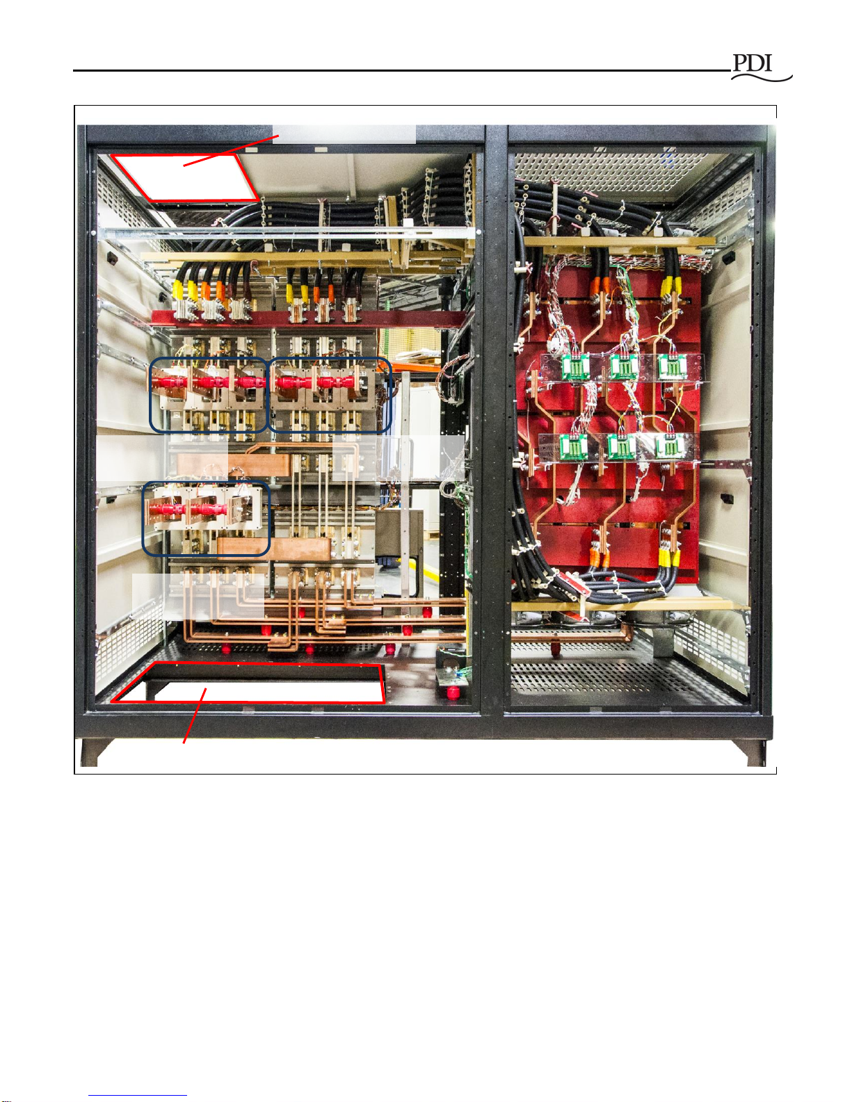
Figure 4 STS 2000A Rear View, Panels Off
Cable Entry/Exit
Cable Entry/Exit
Source 2 Bus
Connections
Output Bus
Connections
Source 1 Bus
Connections
System Description
Ctrl Nr: PM375118-004 13
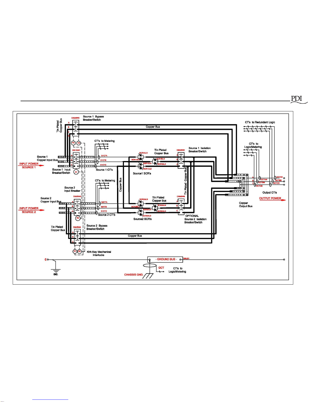
Figure 5 STS 2000A 3-Pole One-line Diagram

WaveStar Static Transfer Switch 2000A 3-Pole
14 Ctrl Nr: PM375118-004
Notes to Figure 5, STS 2000A One-line Diagram:
1. Customer connections
2. Factory connections
3. 2000A STS is equipped with redundant fans.
1.3 Transfer Process: Algorithms
1.3.1 The Problem of Transformer Current Inrush
One of the limiting factors in using an STS in mission critical facilities has been the inability of the electrical
infrastructures to withstand the transformer inrush when switching occurs on the primary side of the transformer,
typically at 480VAC. When downstream transformers saturate, currents can rise to 10-12 times the transformer
rating, creating an outage by tripping circuit breakers and molded case switches in the STS or in UPSs upstream
of the STS.
PDI’s patented Volt Second Synchronizing (VSS) algorithm solves this problem, dramatically reducing the
current rise or inrush when transferring between sources. Transformer inrush is limited to (1.5) x the transformer’s
full load current rating, but is typically less than (1) x transformer rating.
1.3.2 Sense and Transfer Algorithms
Sense algorithms detect that the active power source is going out of specification and that a transfer is required.
PDI has optimized STS sense algorithms experimentally, but algorithm parameters can be adjusted by
administrators if necessary.
Transfer algorithms move the load to the other source. Transfers are not performed by connecting the two
sources (“Make before Break”), which would cause cross-currents between sources.
Administrators can choose between two transfer algorithms using the front panel touchscreen:
•POG (Power or Gate) (fast) algorithm transfers the load as quickly as possible from one source to
another without connecting the sources together.
•Automatic transfers including sense time are ≤ 1/4 cycle for all phase conditions.
•Manual transfers are ≤ 1/8 cycle for in-phase conditions (phase-synchronized sources).
•VSS (low inrush) algorithm transfers the load in 3/4 of a cycle or less, including sense time, and will
balance the volt seconds of any magnetic load so as to not draw in-rush current.
•Automatic transfers are ≤ 3/4 cycle for all phase conditions, including sense time.
•Manual transfers are ≤ 1/8 cycle for in-phase conditions.
The STS 2000A can successfully switch the load between sources that are 180⁰out-of-phase within the above-
specified cycle times.
VSS is the recommended and default algorithm and should be used whenever there are transformers
downstream of the STS, including small transformers embedded in devices. The POG algorithm can be used
when there are no downstream transformers.
System Description
Ctrl Nr: PM375118-004 15
1.4 Transfer Process: Power Switching Components
There are three sets of Molded Case Circuit Breakers (MCCBs) or Molded Case Switches (MCSWs) controlling
whether the system is in Normal or Bypass Mode and two sets of SCRs, which provide power switching for
transfers:
•Source 1 MCCB and Source 2 MCCB are breakers from the two power sources to the SCRs.
•SCR 1 and SCR 2 open or close to control which source powers the load.
•Bypass 1 MCCB and Bypass 2 MCCB are used to shunt power around STS logic and power switching
elements for maintenance.
•Isolation 1 MCSW and (optional) Isolation 2 MCSW isolate components for maintenance during Bypass
Mode. The second optional isolation MCSW provides redundancy.
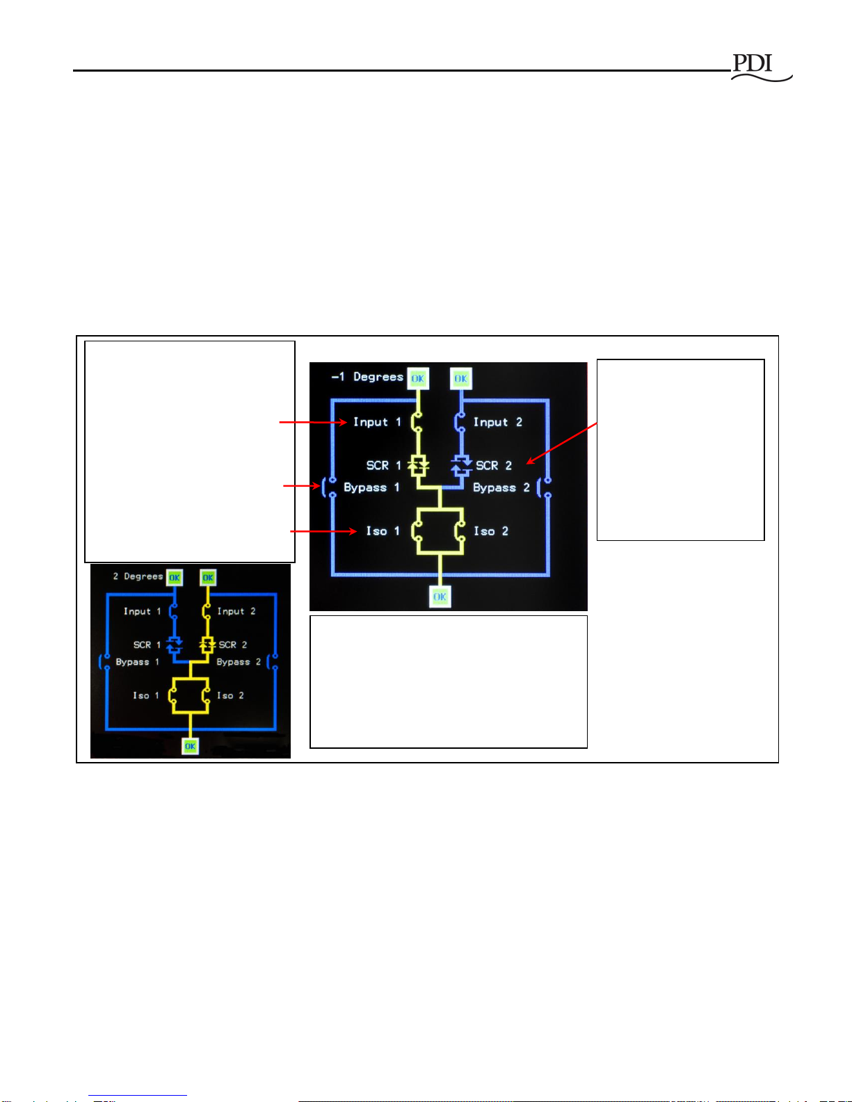
Figure 6 Normal Mode MCCB/MCSW and SCR Configuration
In Normal Mode operation (Figure 6), the Monitor controls the transfer process:
•The MCCBs for Source 1 and 2 are both closed, allowing a power path from either source, hence
allowing the load to be automatically transferred from one source to the other.
•The Isolation MCSWs are closed to provide a power path for either source.
•System logic opens or closes SCR 1 or SCR 2 to transfer the load rapidly from one source to the other.
•Bypass 1 and 2 MCCBs are both open while the bypass is unused.
The Monitor logic continuously monitors the two power sources using its sensing algorithms and controls
transfers, using the POG or VSS algorithm, as specified by the user. The Monitor is itself continuously monitored
In Normal Mode, breakers
(MCCBs and MCSWs) are fixed
in the open/closed configuration
shown here.
-Source (Input) 1 and 2 MCCBs
are both closed, allowing either
source to power the load.
-Bypass breakers are both open.
-The Isolation (Iso) MCSWs are
closed to allow a power path from
either source.
In Normal Mode,
-SCRs determine the
active power path under
control of system logic. In
this illustration,
-SCR 1 is closed (active
path).
-SCR 2 is open (inactive
standby path).
One-line Diagrams
are from the Home
screen.
In the illustration to the left,
- Source (Input 2) is powering the load.
- SCR 2 is closed, SCR 1 open.
- Isolation switches are closed to allow a
power path from either source.
Note: Only (1) Isolation Switch is required;
(2) Isolation Switches provide redundancy.
WaveStar Static Transfer Switch 2000A 3-Pole
16 Ctrl Nr: PM375118-004
by the Simple Algorithm Switch (SAS), which provides a backup transfer process using a simpler algorithm, if the
Monitor fails.
In Bypass Mode operation (Figure 7), operators isolate logic and power components for maintenance by changing
the open/closed MCCB and MCSW states. Kirk Keys enforce correct coordination between breakers, preventing
cross-currents between sides.
1.5 High Availability through Redundancy
To keep a mission-critical load continuously supplied with power, the STS must itself be continuously operational.
To the fullest extent practical, the STS 2000A employs redundant circuits and components to eliminate single
points of failure.
•The STS is designed for an MTBF exceeding 2,000,000 hours.
•The STS has dynamic tri-redundant logic with voting circuits. Each level monitors the power being
supplied to the load, if one level does not transfer the load in specified times, the second level will transfer
the load within the CBEMA/ITS curve.
•The STS has quad-redundant gate drivers, redundant drivers for each set of SCRs. The drivers cannot
inhibit or out vote the other. Therefore, both source 1 and source 2 SCRs have two levels of isolated,
independent gate drivers.
•The STS has tri-redundant logic power supplies. The configuration of each DC logic power supply is
such that a short circuit on one PCB cannot prevent the other PCBs from receiving tri-redundant power.
Each PCB receives logic power via three isolated connectors.
•The STS has N+3 fan redundancy for forced air-cooling of the SCRs.
•The STS uses tri-redundant fiber optic lite pipes and circular redundant CAN Bus to route logic signals
between logic PCBs.
•Noise immune signal buses: the STS uses optical buses and/or CAN buses to route signals between
logic PCBs.
•All signal buses are tri-redundant.
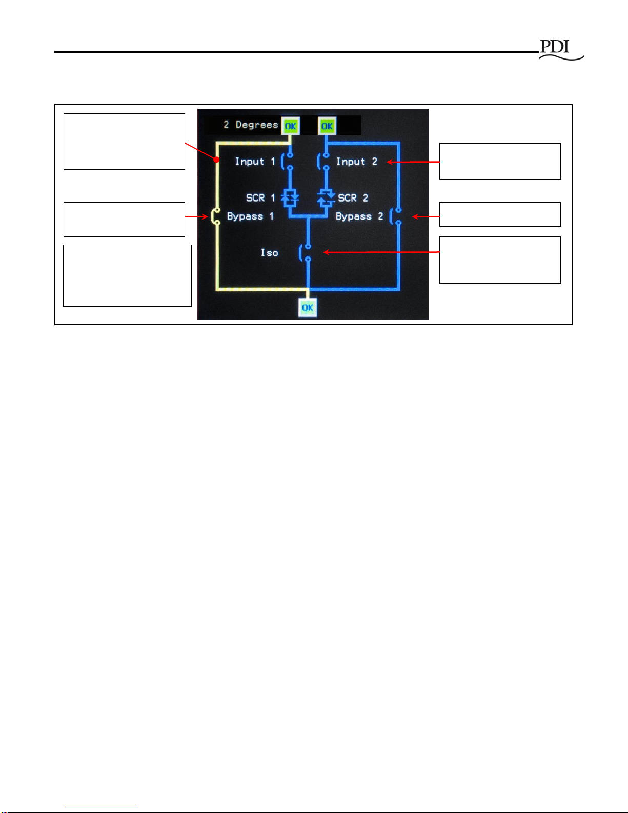
Source (Input) 1 and 2
MCCBs are open.
Isolation MCSW 1 is
open.
Bypass MCCB 2 is open.
Bypass 1 MCCB is
closed.
STS is on Bypass 1.
Bypass 1 is the active
power path (yellow).
When the STS is on
Bypass 2,
-Bypass 1 MCCB is open.
-Bypass 2 MCCB is closed.
One-line Diagram is
from the Home screen.
Figure 7 STS on Bypass (Bypass 1)

System Description
Ctrl Nr: PM375118-004 17
•Each signal bus continuously transmits “bus integrity” signals, when not transmitting true data. If the
“bus integrity” signals are not received by all receivers, then that bus is considered discontinuous and
is alarmed.
•The CAN Bus has circular redundancy so that there are two paths. One path can be severed and
signals will continue to flow via the other path.
•The STS has two levels of operator controls and status displays. The Monitor and display is backed
up by the Redundant Operator Interface (ROI).
1.6 Operational Information and Controls
The STS has a color graphics touchscreen, a backup operator interface (the ROI), help screens, and audible
voice assistance that supplements the display in certain situations.
1.6.1 Graphics Touch-Screen Monitor/Display
The STS has a front touchscreen display that can display the following information:
•A dynamic one-line mimic display, showing the active source-to-output path, bypass, and measurements
(See Figure 3, Operator Interfaces: Touchscreen Display and Redundant Operator Interface)
•Setup and configuration settings
•Administrative and operational controls
•Alarm Log and Event Log
•AC wave form capture for transfer events or displaying the current wave structure
•Digital and Analog Points (Modbus registers)
•Voltage and current measurements for input sources and output load
•Harmonics for both voltage and current
•Load trending
1.6.2 Operational Assistance
•The Voice Unit annunciates alarms (“Static switch, new alarm”) and cleared alarms at the unit and
provides operator cautions (“You are not authorized for this function”).
•The Help function provides both text and voice-over instructions to guide operators through transfer tasks
for going to Bypass Mode and returning from Bypass to Normal Mode. The instructions are context-
specific, providing information for transfers appropriate to the current STS source-to-output connections.
1.7 System Security
The STS 2000A is designed for mission-critical environments and has security features appropriate to that
environment:
•The administrator assigns each user a unique Personal Identification Number (PIN) associated with an
access level, such as administrator or operator, determining what actions the user can perform.
•A PIN and password are required to login.
•No changes to system parameters or STS operation can be made through the touchscreen Monitor
without a valid user login, and no changes at all can be made remotely via web access.

WaveStar Static Transfer Switch 2000A 3-Pole
18 Ctrl Nr: PM375118-004
•Only one user can be logged in at a time. The Event Log records and time-stamps the user’s login,
changes to parameters or actions while the user is logged in, and the user’s logout.
•Doors require a key to be opened, controlling access to the MCCBs/MCSWs, ROI, and components.
•When an STS font door is opened, the unit alarms and the alarm is logged into the Event Log.
1.8 Communications
The STS 2000A can transmit alarms, status, and waveform data to remote locations and receive control signals
using several communications methodologies:
•Modbus RTU using RS422/485 (4-wire or 2-wire)
•Ethernet 10/100 Mb supporting these protocols:
•ModBus TCP/IP
•HTTP for the STS web server, providing web browser access to display pages
•SNMP (Simple Network Management Protocol)
•SNTP (Simple Network Time Protocol) for time synchronization
•SMTP (Simple Mail Transfer Protocol) for E-mail summary alarm alerts
•Land line 9600 Modem for dial out summary alarm notification
•Dry contact input and output signals, used for status conditions, summary alarm notification, remote EPO,
and remote switching of input sources
•USB download of the Event Log using the display’s USB port
All of the above communications methods can be used simultaneously.
1.9 Optional Features
The STS 2000A 3-pole has these optional features:
•A second MCSW Isolation Switch, providing redundancy for the Isolation Switch
•Enhanced Contractor Board, providing additional dry contact and communications options (see 5.1.2
Enhanced Contractor Board Connections and other Chapter 5 sections)
•Multi-Switch Link Option, allowing an N+1 UPS configuration (see 5.3.4 Multi-Switch Link Option)
1.10 Standards Compliance
The STS 2000A system is listed to these standards:
•Underwriters Laboratories: listed to UL standard 891.
•ETL: listed to UL1008 and to applicable parts of CSA 22.2.
The STS 2000A system is also designed, manufactured, tested, and installed, as applicable, in accordance with
these standards:
•American National Standards Institute (ANSI)
•Canadian Standards Association (CSA)

System Description
Ctrl Nr: PM375118-004 19
•Institute of Electrical and Electronics Engineers (IEEE)
•National Electrical Code (NEC)
•National Electrical Manufacturers Association (NEMA)
•National Fire Protection Association (NFPA)

WaveStar Static Transfer Switch 2000A 3-Pole
20 Ctrl Nr: PM375118-004
2Installation Planning
This chapter has planning information for the 3-pole STS 2000A. Additional specifications and planning
information can be found in the following:
•Chapter 5 Customer Communications Connections
•GUIDE SPECIFICATION PDI 2000 Amp 3-Pole Static Transfer Switch
2.1 System Enclosure
The STS 2000A enclosure is designed for the data center or telecommunications environment. The
enclosure is shown in Figure 1, STS 2000A 3-pole, General Assembly Drawing, and enclosure details are
listed below.
•NEMA-1 rated
•Dimensions: 90"W x 60"D x 84"H
•Enclosure is primed and painted with suitable semi-gloss enamel both inside and out. The Color
is Pearl White with black top venting.
•Large cable entry/exit openings top and bottom:
•Top entry: 33.75" x 29.00"
•Bottom entry: 37.50" x 25.50"
•STS weight is approximately 5400 lbs.
2.2 Clearances and Service Access
•Ventilation clearances required:
•6" both sides
•24" overhead
•Service clearances required:
•30" front and rear service clearance
•Front and rear access is required for installation and maintenance.
•All input and output power connections must be made from rear of the unit.
•For ease of servicing:
•All control and logic components are mounted separately from the power components.
•All MCCBs and MCSWs are draw-out type for ease of replacement.
2.3 Cooling
The STS uses forced air cooling and rejects heat through removed protected openings in the top and
bottom of all modules.
Table of contents


