PEAK COMMUNICATIONS DBUH Series User manual

Handbook Issue 3.20, 12th March 2017
1997
EN 55022 CLASS B
EN 50082-1
EN 60950
PEAK COMMUNICATIONS Ltd.
Unit 1, The Woodvale Centre, Woodvale Road,
Brighouse, West Yorkshire
HD6 4AB, England
Phone 01484 714200
Fax 01484 723666
IMPORTANT NOTE: THE INFORMATION AND SPECIFICATIONS CONTAINED IN THIS
DOCUMENT SUPERCEDE ALL PREVIOUSLY PUBLISHED INFORMATION CONCERNING
THIS PRODUCT
PEAK COMMUNICATIONS Ltd maintains a continuing programme of product improvement
and therefore reserves the right to change specifications without notice
Installation and Operating Handbook
DBUH / DLAH / DTLH Dual Hot Swappable
Converters/ Line Amplifiers /Test Loop
Translators

Issue 3.20 DBUH / DLAH / DTLH Installation and Operation Handbook Page 2
Table of Contents
INTRODUCTION.................................................................................................................................................................... 3
EMC AND SAFETY................................................................................................................................................................ 3
EMC...................................................................................................................................................................................... 3
Safety................................................................................................................................................................................... 4
INSTALLATION ...................................................................................................................................................................... 4
UNIT DESCRIPTION............................................................................................................................................................. 5
Front Panel Description......................................................................................................................................................... 5
Keyboard ............................................................................................................................................................................ 5
LCD display........................................................................................................................................................................ 5
LED Indicator..................................................................................................................................................................... 5
REAR PANEL DESCRIPTION ............................................................................................................................................. 5
REAR PANEL PINOUTS....................................................................................................................................................... 6
OPERATION........................................................................................................................................................................... 7
Menu Structure........................................................................................................................................................................ 7
Operating display............................................................................................................................................................. 7
Status .................................................................................................................................................................................. 7
Configure............................................................................................................................................................................ 8
Attenuation......................................................................................................................................................................... 8
Remote control.................................................................................................................................................................. 8
Log..................................................................................................................................................................................... 10
Service............................................................................................................................................................................... 10
REDUNDANCY / MUTE...................................................................................................................................................... 11
WEBSITE PASSWORDS / SNMP COMMUNITIES........................................................................................................ 12
Setup.................................................................................................................................................................................. 13
REMOTE CONTROL........................................................................................................................................................... 14
Serial Communications RS232 / 485.......................................................................................................................... 14
Ethernet............................................................................................................................................................................. 21

Issue 3.20 DBUH / DLAH / DTLH Installation and Operation Handbook Page 3
INTRODUCTION
The equipment’s covered by this manual are high grade units which can be applied to many
situations where good stability and phase noise etc are required.
The specification for the particular model purchased can be found at the end of this manual.
EMC AND SAFETY
EMC
The equipment has been designed to comply with the following standards;
Emissions : EN 55022 Class B; Limits and methods of measurement of radio interference
characteristics of Information Technology Equipment.
Immunity : EN 50082 Part 1; Generic immunity standard, part 1: Domestic, commercial and
light industrial environment.
The equipment must be operated with its lid on at all times. If it is necessary to remove the lid for
routine servicing or fault finding then it is essential that the lid is fitted back correctly before normal
operation.
For the Alarm and Remote Control data interfaces all 'D' type connectors must have grounding
fingers on the plug shell to guarantee continuous shielding. The back-shells must comply to the
requirements of VDE 0871 and FCC 20708, providing at least 40 dB of attenuation from 30 MHz
to 1 GHz.
Connecting cables must be of the shielded type
Operation of the equipment in a non standard manner will invalidate compliancy to these
standards.

Issue 3.20 DBUH / DLAH / DTLH Installation and Operation Handbook Page 4
Safety
To ensure safety of the operator the equipment has been designed to comply with the following
safety standard;
EN 60950 Safety of information technology equipment, including electrical business machines.
Before operation the user must ensure that the installation complies with the information given.
The equipment is designed to operate in a static 19 inch rack system conforming to IEC 297-2.
Operation of the equipment in transportable vehicles equipped with the means of providing a
stable environment is permissible. Operation of the equipment on board vehicles, ships or aircraft
without means of environmental conditioning will invalidate the safety compliancy; please contact
the factory for further advice. Operation of the equipment in an environment other than that stated
in the specifications will also invalidate the safety compliancy. The equipment must not be
operated above 2000 metre altitude, extremes of temperature; excessive dust, moisture or
vibration; flammable gases; corrosive or explosive atmospheres.
INSTALLATION
The equipment is classified in EN 60950 as a pluggable equipment class A for connection to the
mains supply, as such it is provided with a mains inlet cord suitable for use in the country of
operation. In normal circumstances this will be of an adequate length for installation in the rack. If
the mains cord proves to be too short then any replacement must have a similar type fuse (if
fitted) and be manufactured to similar specification: check for HAR, BASEC or HOXXX-X ratings
on the cable. The connector ends should be marked with one of the following : BS1636A (UK free
plug 13 amp); BSI, VDE, NF-USE, UL, CSA, OVE, CEBEC, NEMKO, DEMKO, SETI, IMQ, SEV
and KEMA-KEUR for the IEC 6 amp free socket. Schuko and North American free plugs must
have similar markings.
The installation of the equipment and the connection to the mains supply must be made in
compliance to local or national wiring regulations for a category II impulse over voltage
installation. The positioning of the equipment must be such that the mains supply socket outlet for
the equipment should be near the equipment and easily accessible or that there should be
another suitable means of disconnection from the mains supply.
The equipment is designed to operate from a TN type power supply system as specified in EN
60950. This is a system that has separate earth, line and neutral conductors. The equipment is
not designed to operate with an IT power system which has no direct connection to earth.

Issue 3.20 DBUH / DLAH / DTLH Installation and Operation Handbook Page 5
UNIT DESCRIPTION
STATUS
CANCEL
NO / 6 7 8 9 0
ENTER
YES / 1 2 3 4 5
DUAL BLOCK UNIT
DLAH200
115/230 VOLTS AC
PSU1
MODEL NO.:
A2
UB1
50/60 Hz UA1 SERIAL NO.:
OutputInput 1
MODEL NO.:
Ethernet 2
Interface
Input Output
SERIAL NO.:
UB2
A2
UA2
Ext Ref.
50 Watts Max
PSU2
Front Panel Description
Keyboard
The keyboard is of the membrane type and is an integral part of the front panel assembly. The
front panel overlay and is completely sealed against penetration of liquids but caution should
be taken especially with solvents which may damage the front screen.
There are 16 keys in total - number keys in the range 0 to 9, YES/ENTER and NO/CANCEL
and a 4 way arrow block of keys
LCD display
The backlit display is a graphic display and characters are scaled to incorporate as much
information as possible on the screen. It provides detailed information about the status and
configuration of the unit, and when appropriate, prompts the user to enter data via the keypad.
LED Indicator
Only one tricolour LED is present, marked STATUS. This shows GREEN when the unit is OK,
RED when an internal fault is present and AMBER when in STANDBY (Redundancy operation)
An Internal alarm is caused by Power failure, Amplifier failure or Unit out of lock.
REAR PANEL DESCRIPTION
EXT. Ref External Reference input.
Interface Alarms connection.
Ethernet Ethernet connection if option is fitted.
Other rear panel connections maybe applicable to the specific unit purchased please check the
specification.

Issue 3.20 DBUH / DLAH / DTLH Installation and Operation Handbook Page 6
REAR PANEL PINOUTS
INTERFACE Alarms monitoring and control of the units.
REMOTE (If Ethernet option is not fitted) Alarms monitoring and control of the units.
Ethernet (If option fitted)
RJ45 8P8C female connector
Module 2 Amplifier N/C
1
Module 2 Amp Common
2
Module 2 LO N/O
3
Module 2 LO Common
4
Module 2 Summary Alm N/O
5
Module 2 Summary Alm
Common
6
Module 2 Online
7
Ground
8
9
Module 1 Amplifier N/C
10
Module 1 Amp Common
11
Module 1 LO N/O
12
Module 1 LO Common
13
Module 1 Summary Alm N/O
14
Module 1 Summary Alm
Common
15
Module 1 Online
RS485 Rx +
1
RS485 Tx +
2
Not used
3
Not used
4
Not used
5
Not used
6
RS232 Rx In
7
Not used
8
9
RS485 Rx -
10
RS485 Tx -
11
Not used
12
Not used
13
Not used
14
GROUND
15
RS232 Tx Out

Issue 3.20 DBUH / DLAH / DTLH Installation and Operation Handbook Page 7
OPERATION
On switching on the unit the STATUS indicator on the front of the unit should turn GREEN if all
is OK.
The modules are inserted from the rear of the DBUH/DLAH, please refer to the DBUH/DLAH
datasheet for the inserted modules’ performance.
Menu Structure
On Power up the unit will start in HOME mode displaying the following options.
Generally YES will select/enable an item and NO will step back one step with no changes.
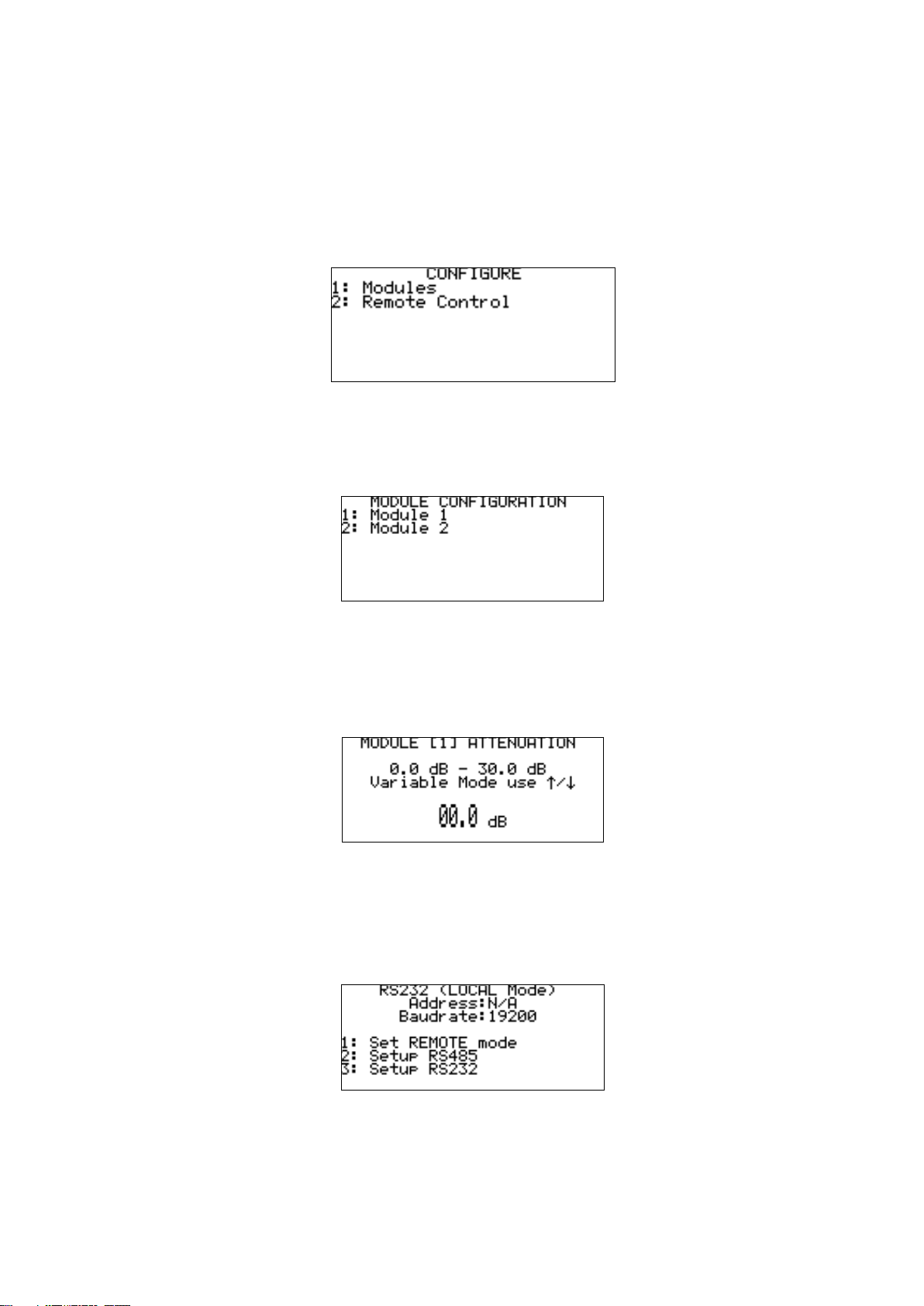
The unit’s HOME screen has 5 main menu options as shown in Figure 1 below:
Operating display
This menu shows a graphical representation of the RF path and attenuation values, the screen
is different if the unit is fitted with the redundancy option.
Figure 2
Status
This menu shows an immediate summary of all settings and alarm conditions, more details
may be available by pressing the down arrow, left and right arrows cycle through the attached
trays.
Figure 1
Figure 3
Issue 3.20 DBUH / DLAH / DTLH Installation and Operation Handbook Page 8
Configure
This menu allows the user to configure different parts of the unit, the menu choice change
depending on the unit, its options, and whether the unit is in remote or local mode.
When in local mode all the menu items are available to the user to change, when in remote
mode only the REMOTE CONTROL menu option is available.
Figure 3, below, shows a basic configure menu, however as stated above the menu choices
change depending on the unit, the installed trays and their options.
The possible list of tray options that have their own configure menu items and associated
configuration screens including:
Figure 5
Attenuation
Allows the attenuation of the RF path of the selected tray to be changed, the step size and
range are tray/option specific.
Remote control
Selects a sub-menu with further menus. If the Ethernet module is not installed then the
following menu will be shown:
Figure 4
Figure 7
Figure 6
Issue 3.20 DBUH / DLAH / DTLH Installation and Operation Handbook Page 9
1 Set REMOTE mode - Sets the unit to allow control from a remote source. Pressing 1 again
returns the unit to local mode.
2 SETUP RS485 - Allows the selection of RS485 UNIT ADDRESS and BAUD RATE.
3 SETUP RS232 - Allows selection of BAUD RATE for RS232 communication.
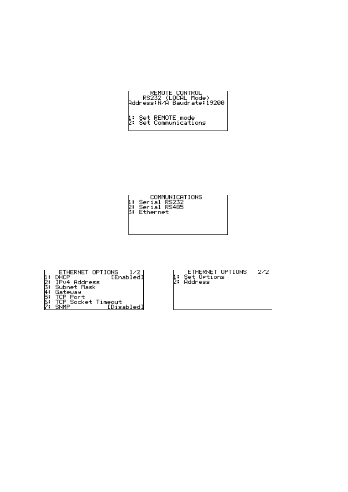
If the Ethernet module is fitted then the menus change slightly to:
1 Set REMOTE mode - Sets the unit to allow control from a remote source. Pressing 1 again
returns the unit to local mode.
2 Setup Communications - Allows the selection of RS485, RS232 or Ethernet communication.
RS232, RS485 menus work in the same way as shown above.
3 Ethernet –This brings up a further menu as shown below in figures 11 and 12, these are
accessed by using the up/down buttons
The menu choices (1-4) shown in figure 11 allow the user to change the relevant Ethernet
settings of the unit.
5 TCP Port –Sets the TCP port number used that allows serial comms messages to be sent,
via Ethernet, to the unit.
6 TCP Socket Timeout –Sets the timeout value, after which time if no communication is
received on the open TCP socket it is closed.
7 SNMP –Allows the SNMP protocol to be turned Disabled/Enabled.
1 SNMP Trap Address –Sets the IP address of the device that will receive any SNMP trap
error messages from the unit.
Set Options in figure 12 is used to set the Ethernet data all at once on the device, this must be
used when trying to change the Ethernet settings.
Figure 8
Figure 9
Figure 10
Figure 11
Issue 3.20 DBUH / DLAH / DTLH Installation and Operation Handbook Page 10
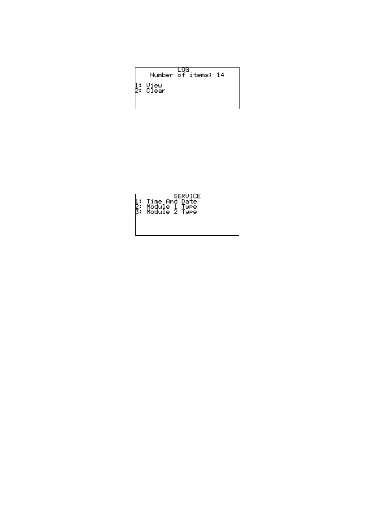
Log
This provides an event log of any ‘errors’or ‘events’that have occurred.
1 View - Displays the stored logs.
2 Clear - Allows the user to clear the log.
Service
This menu has 3 submenus as shown below in figure 13.
1 Time And Date - Allows setting of current time and date
2 Module 1 Type - Allows selection of installed module type
3 Module 2 Type - Allows selection of installed module type
Figure 12
Figure 13
Issue 3.20 DBUH / DLAH / DTLH Installation and Operation Handbook Page 11
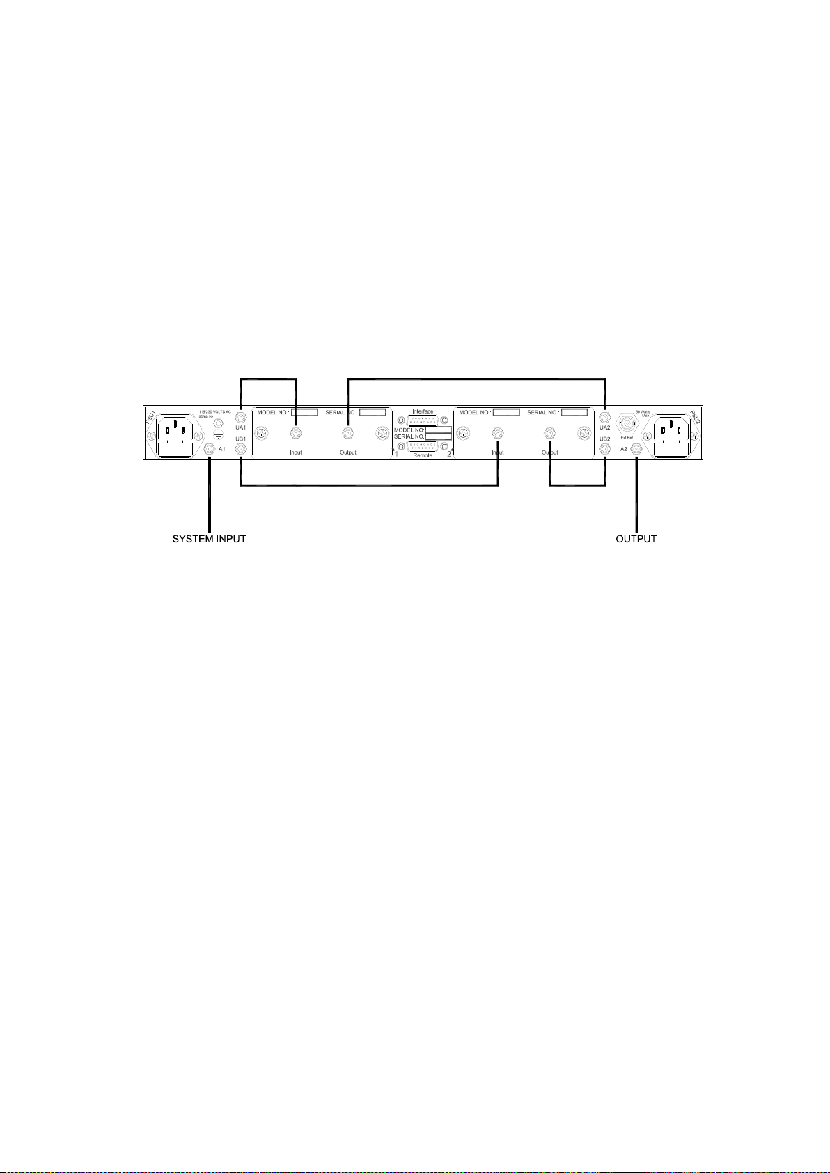
REDUNDANCY / MUTE
The redundancy option allows the user to select which tray is online, either A or B. Alternatively,
Auto mode can be selected, allowing the automatic switching in/out of faulty trays.
If the unit also has the mute option fitted, then the output of the redundancy system can be
muted via one of the unit’s user interfaces e.g. menu.
Where the DBUH/ DLAH/ DTLH is purchased as a redundant system with two identical MBUH/
MBDH/ MLAH/ MTLH modules, the rear panel cabling configuration is shown below.
The customer is required to supply the system input and output cables. Peak Communications
will supply the interconnecting cables unless instructed otherwise.

Issue 3.20 DBUH / DLAH / DTLH Installation and Operation Handbook Page 12
WEBSITE PASSWORDS / SNMP COMMUNITIES
From DXXH software version 1.32 onwards the website offers a simple form of password
protection for the webpages, as well as the ability to change the SNMP community names.
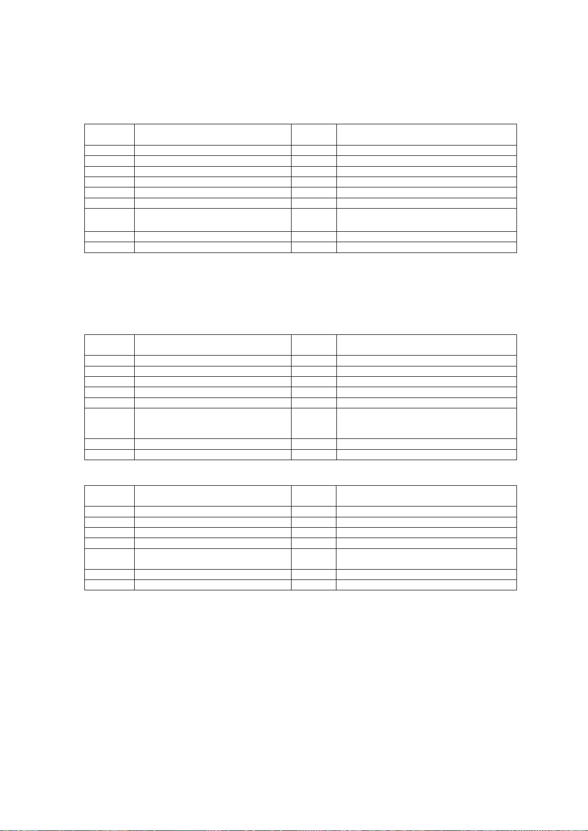
There are two user logins for the webpages, these are shown in the table below, along with
their default user names and passwords:
Type
User Name
Password
Description
Read only
readonly
readonly
Access to status
pages only.
Read write
readwrite
readwrite
Access to status and
config pages.
The default SNMP community names are shown in the table below:
Community
Name
Read
public
Set / write
private
In order for webpages to be accessible the user must login, using one of the above usernames.
The logged in user name and password can be changed via the website.
When using the read write user, the SNMP community names can also be changed.
The passwords are as standard disabled, they can be enabled via the front panel of the unit.
The default passwords / SNMP community names can also be reset to their default via the front
panel.

Issue 3.20 DBUH / DLAH / DTLH Installation and Operation Handbook Page 13
Setup
This menu, as shown in figure 14, is hidden and shouldn’t normally be used by operators.
However this is the menu that allows the resetting of passwords / communities, as well as
toggling the passwords on / off.
In order to get to this setup menu, the user presses keys 0 then 9 from the HOME menu.
1 Initial Setup –Allows the initial setup of the unit, this SHOULD NOT BE USED BY
CUSTOMERS AS A BAD SETUP MAY CAUSE PERMANENT UNIT DAMAGE.
2 Serial Number –Allows the setting of the unit’s serial number.
3 Modify Parameters - Allows modification of certain unit parameters. DO NOT USE
4 Program Checksum –Calculates the firmware checksum.
5 Reset Passwords –Resets all the passwords and community names back to their default
values, and turns the passwords / security off.
6 Toggle Passwords –Toggles the passwords / security on / off.
Menu items 5 & 6 are not available in Non Ethernet based units.
Figure 14

Issue 3.20 DBUH / DLAH / DTLH Installation and Operation Handbook Page 14
REMOTE CONTROL
Serial Communications RS232 / 485
The unit transmits and receives data serially in an asynchronous format using the standard
ASCII character set. The serial data consists of message frames composed of the following
message characters: STX, BYTE COUNT, UNIT ADDRESS, INSTRUCTION, BODY,
CHECKSUM, ETX. All characters are compulsory except for the message body. The presence
of a message body is determined by the message type (INSTRUCTION). The total number of
message characters in a message frame may range from a minimum of 6 to a maximum of
255.
The remote control follows the following protocol: (in byte form)
[STX] start of message character #02.
[B] char defining how many characters are in the message including the STX & ETX parts.
[A] Address of unit. Address ranges from ASCII character 001 to 255. If in RS232 Mode
this address can be anything in the 001 to 255 range.
[I] Instruction number. See List below
[MESSAGE]
Numerous characters from length 0 upwards.
[CHKSUM]
The checksum is used to verify the accuracy of the message frame. The checksum is
defined as the summation of all the bytes in the message, beginning with the 3rd byte
(DEVICE ADDRESS) and extending through the body of the message, ending with the
last byte before the checksum. The total of the bytes is then ANDed with 255 so that the
checksum is truncated to a single byte.
[ETX] End of transmission character #03
All message to and from the unit follow the above protocol with a character format of 8 data
bits, one stop bit, no parity, baud rate 19200, 9600, 4800, 2400, 1200 or 300. Note; that all
numeric values are shown as decimal.

Issue 3.20 DBUH / DLAH / DTLH Installation and Operation Handbook Page 15
INSTRUCTION NUMBER LIST (IN DECIMAL)
To unit
From unit
Description
20
Requests Status
Allows different status request types:
Module Status Request
Power Supply Status Request
System Status Request
21
Responds Status
Allows different status response types:
Module Status Response
Power Supply Status Response
System Status Response
22
Reconfiguration Request
Single Channel Reconfiguration Request
System Reconfiguration Request
24
Set Remote/Local Mode request
40
Asks for the main Unit settings
41
Replies with the Unit Settings
42
Asks for the internal redundancy status
43
Replies with the internal redundancy status
44
Reconfiguration request for the internal redundancy.
Instruction 20 (Module Status Request)
Message
Byte No.
Set Value /
(example)
Length
(bytes)
Description
1
02
1
STX
2
?
1
No of bytes in message
3
?
1
Address
4
20
1
Message instruction
5
‘M’
1
Module
6
‘01’
2
Module number
8
?
1
Checksum
9
03
1
ETX

Issue 3.20 DBUH / DLAH / DTLH Installation and Operation Handbook Page 16
Instruction 20 (Power Supply Status Request)
Instruction 20 (System Status Request)
Instruction 21 (Module Status Request Reply)
Due to the ability of the DBUH/DLAH to accept differing module types into it, the module status request reply may
vary between these different module types.
If the channel is missing then the value of the rest of the bytes in the message is
undetermined.
Message
Byte No.
Set Value /
(example)
Length
(bytes)
Description
1
02
1
STX
2
?
1
No of bytes in message
3
?
1
Address
4
20
1
Message instruction
5
‘P’
1
Power supply
6
‘01’
2
Power supply number
8
?
1
Checksum
9
03
1
ETX
Message
Byte No.
Set Value /
(example)
Length
(bytes)
Description
1
02
1
STX
2
?
1
No of bytes in message
3
?
1
Address
4
20
1
Message instruction
5
‘S’
1
System
6
?
1
Checksum
7
03
1
ETX
Message
Byte No.
Set Value /
(example)
Length
(bytes)
Description
1
02
1
STX
2
?
1
No of bytes in message
3
?
1
Address
4
21
1
Message instruction
5
‘M’
1
Module
6
‘01’
2
Module number
8
‘-’
1
Module State:
Module Missing ‘X‘
Module Warmup ‘W’
Module Reference Warmup ‘R’
Module Present '-'
9
‘ MLAH175’
20
Module name/type
29
‘+123’
4
Attenuation asked for in 0.1 dB steps,
‘+123’ = 12.3dB
33
‘0’
1
External Reference
‘X‘ = Not present
‘L’ = Locked
‘U’ = Unlocked
34
‘….’
4
NOT USED
38
‘0’
1
Summary Alarm
‘0’ = OK ‘1’ = FAULT
39
‘0’
1
External Reference Fault
‘0’ = OK ‘1’ = FAULT
40
‘0’
1
PLO Fault
‘0’ = OK ‘1’ = FAULT
41
‘0’
1
Amplifier Fault
‘0’ = OK ‘1’ = FAULT
42
‘0’
1
Attenuator Fault
‘0’ = OK ‘1’ = FAULT
43
‘….‘
4
NOT USED
47
(‘23/12/02 12:34:56’)
17
OK Since time/date string, if there is a
fault then the string is blank.
64
?
1
Checksum
66
03
1
ETX

Issue 3.20 DBUH / DLAH / DTLH Installation and Operation Handbook Page 17
Instruction 21 (Power Supply Status Request Reply)
Instruction 21 (System Status Request Reply)
This message should only be used with units with the mute option fitted.
Message
Byte No.
Set Value /
(example)
Length
(bytes)
Description
1
02
1
STX
2
?
1
No of bytes in message
3
?
1
Address
4
21
1
Message instruction
5
‘P’
1
Power supply
6
‘01’
2
Power supply number
‘01’ = PSU 1
‘02’ = PSU 2
8
‘-‘
1
Power Supply Present
‘X’ = Missing ‘-’ = Present
9
‘.’
1
NOT USED
10
‘….’
4
NOT USED
14
‘0’
1
Summary Alarm
‘0’ = OK ‘1’ = FAULT
15
‘0’
1
Power Supply Missing
‘0’ = OK ‘1’ = FAULT
16
‘..’
2
NOT USED
18
(‘23/12/02 12:34:56’)
17
OK Since time/date string, if there is a
fault then the string is blank.
35
?
1
Checksum
36
03
1
ETX
Message
Byte No.
Set Value /
(example)
Length
(bytes)
Description
1
02
1
STX
2
?
1
No of bytes in message
3
?
1
Address
4
21
1
Message instruction
5
‘S’
1
Power supply
6
‘M’
1
Wanted mute status
‘U’ = Unmuted
‘M’ = Mute
7
‘M’
1
Actual mute status
‘U’ = Unmuted
‘M’ = Mute
‘?’ = Unknown
8
‘.….’
5
NOT USED
13
?
1
Checksum
14
03
1
ETX
Issue 3.20 DBUH / DLAH / DTLH Installation and Operation Handbook Page 18
Instruction 22 (Module Reconfiguration Requests)
The unit MUST be in remote mode to allow reconfiguration of parameters via the remote control. Setting the unit in
Remote mode can be done either by the front panel or remotely using the instruction 24.
Due to the ability of the DBUH/DLAH/DTLH to accept differing module types into it, the module status request reply
may vary between these different channel types.
Instruction 22 (System Reconfiguration Requests)
The unit MUST be in remote mode to allow reconfiguration of parameters via the remote control. Setting the unit in
Remote mode can be done either by the front panel or remotely using the instruction 24.
This message should only be used with units with the mute option fitted.
Instruction 24 (Set Remote/Local Mode)
Message
Byte No.
Set Value /
(example)
Length
(bytes)
Description
1
02
1
STX
2
?
1
No of bytes in message
3
?
1
Address
4
20
1
Message instruction
5
‘R’
1
‘R’ = Remote Mode
‘L’ = Local Mode
6
?
1
Checksum
7
03
1
ETX
Message
Byte No.
Set Value /
(example)
Length
(bytes)
Description
1
02
1
STX
2
?
1
No of bytes in message
3
?
1
Address
4
22
1
Message instruction
5
‘M’
1
Module
6
‘01’
2
Module number
8
‘+123’
4
Attenuation in 0.1 dB steps
‘+123’ = 12.3dB
12
?
1
Checksum
13
03
1
ETX
Message
Byte No.
Set Value /
(example)
Length
(bytes)
Description
1
02
1
STX
2
?
1
No of bytes in message
3
?
1
Address
4
22
1
Message instruction
5
‘S’
1
System
6
‘M’
1
Wanted mute status
‘U’ = Unmuted
‘M’ = Mute
7
?
1
Checksum
8
03
1
ETX

Issue 3.20 DBUH / DLAH / DTLH Installation and Operation Handbook Page 19
Instruction 40 (Unit Status Request)
Message
Byte No.
Set Value /
(example)
Length
(bytes)
Description
1
02
1
STX
2
?
1
No of bytes in message
3
?
1
Address
4
40
1
Message instruction
5
?
1
Checksum
6
03
1
ETX
Instruction 41 (Unit Status Request Reply)
Message
Byte No.
Set Value /
(example)
Length
(bytes)
Description
1
02
1
STX
2
?
1
No of bytes in message
3
?
1
Address
4
41
1
Message instruction
5
‘ DLAH200’
27
Type of unit this is: DLAH200 etc
32
‘12345’
5
Serial Number
37
’0112.34’
7
Software Version Number
44
‘0’
1
Summary Alarm OK/FAULT
‘0’ = OK ‘1’ = FAULT
45
‘0’
1
+5V voltage out of range fault
‘0’ = OK ‘1’ = FAULT
46
‘0’
1
-15V voltage out of range fault
‘0’ = OK ‘1’ = FAULT
47
‘0’
1
Temperature out of range fault
‘0’ = OK ‘1’ = FAULT
48
‘0’
1
Internal Communications Fault
‘0’ = OK ‘1’ = FAULT
49
‘0’
1
Coax Switch Fault
‘0’ = OK ‘1’ = FAULT
50
‘0’
1
Ethernet Module Fault
‘0’ = OK ‘1’ = FAULT
51
‘0’
1
Mute Switch Fault
‘0’ = OK ‘1’ = FAULT
52
‘….’
4
NOT USED
56
‘23/12/02 12:34:56’
17
OK Since time/date string, if there is a fault
with this down/up part of the converter
then the string is blank.
73
‘0’
1
Remote mode
‘0’ = Local ‘1’ = Remote
74
?
1
Checksum
75
03
1
ETX

Issue 3.20 DBUH / DLAH / DTLH Installation and Operation Handbook Page 20
Instruction 42 (Internal Redundancy Status Request):
Message
Byte No.
Set Value /
(example)
Length
(bytes)
Description
1
02
1
STX
2
?
1
No of bytes in message
3
?
1
Address
4
42
1
Message instruction
5
?
1
Checksum
7
03
1
ETX
Instruction 43 (Internal Redundancy Status Request Reply):
Instruction 44 (Module Reconfiguration Requests)
The unit MUST be in remote mode to allow reconfiguration of parameters via the remote control. Setting the unit in
Remote mode can be done either by the front panel or remotely using the instruction 24.
If the user is requiring the redundancy mode to be Automatic then the ‘Module to be forced online’ parameter in the
message above is ignored.
Message
Byte No.
Set Value /
(example)
Length
(bytes)
Description
1
02
1
STX
2
?
1
No of bytes in message
3
?
1
Address
4
43
1
Message instruction
5
(‘M’)
1
Redundancy Mode
‘M’ = Manual
‘A’ = Auto
6
(‘1’)
1
Unit Online
‘1’ = Module 1 Online
‘2’ = Module 2 Online
‘?’ = Unknown due to Coax Switch error
7
(‘1’)
1
Copy Settings across from one module to
another when switching
‘0’ = No ‘1’ = Yes
8
(‘1’)
1
Wanted Module Online, i.e. which module
was asked to be forced online
‘1’ or ‘2’
9
?
1
Checksum
10
03
1
ETX
Message
Byte No.
Set Value /
(example)
Length
(bytes)
Description
1
02
1
STX
2
?
1
No of bytes in message
3
?
1
Address
4
44
1
Message instruction
5
(‘M’)
1
Redundancy Mode
‘M’ = Manual
‘A’ = Auto
6
(‘1’)
1
Copy Settings across from one module to
another when switching
‘0’ = No ‘1’ = Yes
7
(‘1’)
1
Module To be Forced Online
‘1’ or ‘2’
8
?
1
Checksum
9
03
1
ETX
This manual suits for next models
3
Table of contents
Other PEAK COMMUNICATIONS Media Converter manuals


Popular Media Converter manuals by other brands

Baumer
Baumer Hubner Berlin HMG 11 Mounting and operating instructions

Itel
Itel STL-SAT Changeover user manual

SWIT
SWIT S-4612 user manual

Advantech Wireless
Advantech Wireless SSPBMg-C400-BRE Installation and operating manual
EnvironmentalLights.com
EnvironmentalLights.com DMX 512 PixelControl manual

Clarity
Clarity U-PAD2 manual


RKC INSTRUMENT
RKC INSTRUMENT COM-K IMR01Z01-E9 instruction manual

Baumer
Baumer HUBNER BERLIN DeviceNet PMG 10 Installation and operating instructions

GRASS VALLEY
GRASS VALLEY ADVC700 - datasheet

DENAFRIPS
DENAFRIPS Terminator manual

AV Access
AV Access 4KIP200 user manual

Becker
Becker VAU 1.1/1-AC operating instructions