Peak PCAN-PC/104-Plus User manual

PCAN-PC/104-Plus
Quad
Four-Channel CAN Interface for
PC/104-Plus
User Manual
V1.0.1

PCAN-PC/104-Plus Quad – User Manual
2
Product Name Model Part Number
PCAN-PC/104-Plus Quad Four CAN channels IPEH-002099
On request you can get the card with stack-through connectors for the ISA bus.
CANopen® and CiA® are registered community trade marks of CAN in Automation
e.v.
All other product names mentioned in this manual may be the trademarks or
registered trademarks of their respective companies. They are not explicitly marked
by “™” and “®”.
© 2012 PEAK-System Technik GmbH
PEAK-System Technik GmbH
Otto-Roehm-Strasse 69
64293 Darmstadt
Germany
Phone: +49 (0)6151 8173-20
Fax: +49 (0)6151 8173-29
www.peak-system.com
info@peak-system.com
Document version 1.0.1 (2012-07-09)

PCAN-PC/104-Plus Quad – User Manual
3
15
1.1 Properties at a Glance 5
1.2 System Requirements 6
1.3 Scope of Supply 7
2
8
2.1 Configuring the Card 8
2.1.1 Setting the Position in the PC/104
Stack 8
2.2 Installing the Software and the Card 10
2.3 Notes for the ISA Bus Stack-through
Connection 12
3
3.1 D-Sub Connector 13
3.2 Supplying External Devices via the CAN
Connector 15
3.3 Cabling 17
3.3.1 Termination 17
3.3.2 Example of a Connection 17
3.3.3 Maximum Bus Length 18
4
4.1 CAN Monitor PCAN-View for Windows 19
4.1.1 Receive/Transmit Tab 21
4.1.2 Trace Tab 23
4.1.3 Status Bar 24
4.2 Linking Own Programs with PCAN-Basic 25
4.2.1 Features of PCAN-Basic 26
4.2.2 Principle Description of the API 27
4.2.3 Notes about the License 28

PCAN-PC/104-Plus Quad – User Manual
5
1
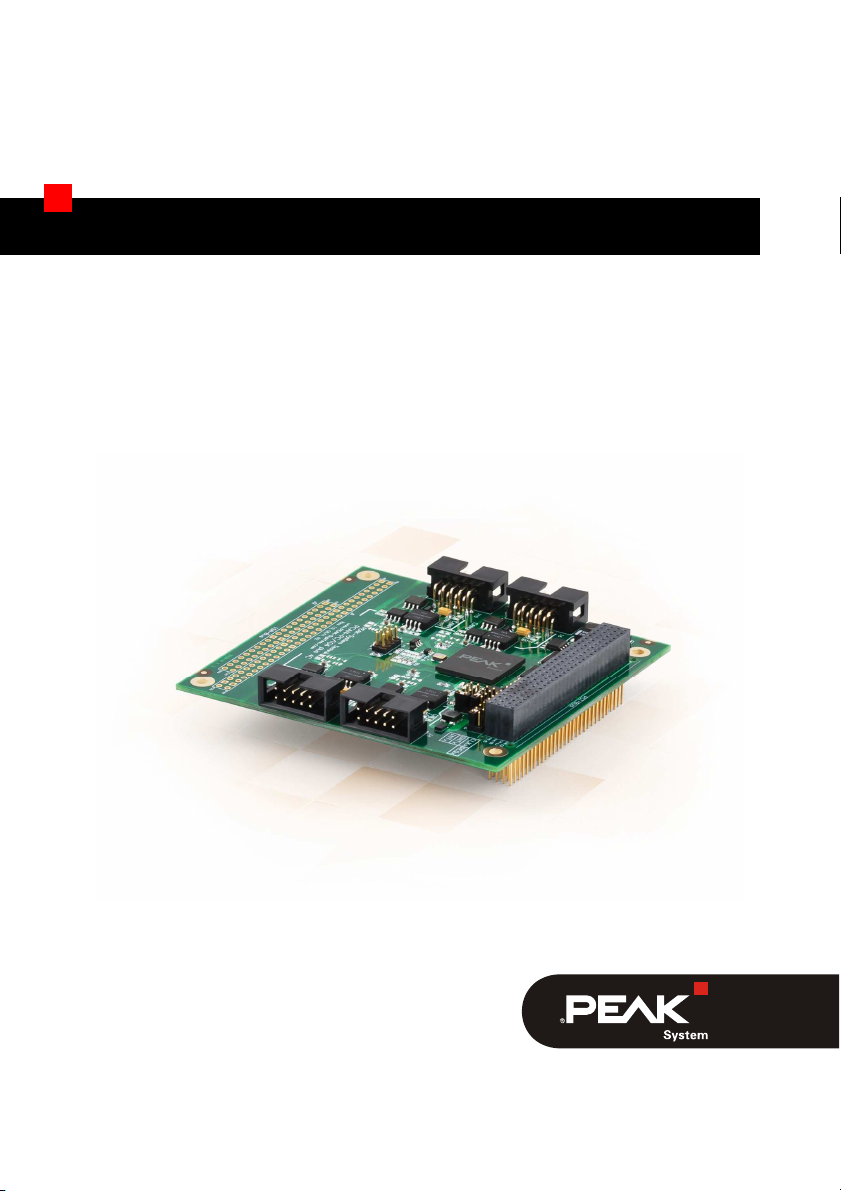
The PCAN-PC/104-Plus Quad card enables the connection of four
CAN networks to a PC/104-Plus system. Up to four cards can be
operated, with each piggy-backing on the next. The CAN bus is
connected using a 9-pin D-Sub plug on the slot brackets supplied.
There is galvanic isolation of up to 500 Volts between the computer
and CAN sides. Device drivers and a programming interface exist
for different operating systems, so programs can easily access a
connected CAN bus.
Tip: At the end of this manual (Appendix C) you can find a
Quick Reference with brief information about the installation
and operation of the PCAN-PC/104-Plus Quad card.
Form factor PC/104
Use of the 120-pin connection for the PCI bus
Up to four cards can be used in one system
Bit rates up to 1 Mbit/s
Compliant with CAN specifications 2.0A (11-bit ID)
and 2.0B (29-bit ID)
Connection to CAN bus through D-Sub slot brackets,
9-pin (in accordance with CiA® 102)
NXP SJA1000-compatible CAN controller
(FPGA implementation)
NXP PCA82C251 CAN transceiver

PCAN-PC/104-Plus Quad – User Manual
6
5-Volts supply to the CAN connection can be connected through
a solder jumper, e.g. for external bus converter
4 High-speed CAN channels (ISO 11898-2)
Galvanic isolation on the CAN connection up to 500 V, separate
for each CAN channel
Extended operating temperature range from -40 to 85 °C
(-40 to 185 °F)
Note: This manual describes the use of the PCAN-PC/104-Plus
Quad card with Windows. You can find device drivers for Linux
and the corresponding application information on the provided
DVD in the directory branch Develop and on our website under
www.peak-system.com/linux.
PC/104 stack with PCI-Bus (according to the specification PC/104-
Plus)
Operating system Windows 7/Vista/XP (32/64-bit)
or Linux (32/64-bit)

PCAN-PC/104-Plus Quad – User Manual
7
PCAN-PC/104-Plus Quad card
Two Slot brackets with D-Sub connectors for the CAN bus
Device drivers for Windows 7/Vista/XP (32/64-bit)
and Linux (32/64-bit)
PCAN-View CAN monitor for Windows
PCAN-Basic programming interface consisting of an interface
DLL, examples, and header files for all common programming
languages
Manual in PDF format

PCAN-PC/104-Plus Quad – User Manual
8
2
This chapter covers the configuration for the PCAN-PC/104-Plus
Quad card and the software setup under Windows and the
installation of the card in the PC/104 stack.
Note: Under Windows the PCAN-PC/104-Plus Quad card is run
as a PCAN-PC/104-Plus card.
Before installing the PCAN-PC/104-Plus Quad card into a PC/104
stack, you must configure it using jumpers on the PCB.
Attention! Electrostatic discharge (ESD) can damage or destroy
components on the PCAN-PC/104-Plus Quad card. Take
precautions to avoid ESD when handling the card.
The PCAN-PC/104-Plus Quad card must be adjusted to a specific
position in the stack by setting the appropriate jumpers. The
position number results from the distance to the host.

PCAN-PC/104-Plus Quad – User Manual
9
Figure 1: Jumper fields IDx, CLKx, and INTx
on the PCAN-PC/104-Plus Quad card
Position in the PC/104 stack in relation to the host
Jumper Signal 1 2 3 4
IDx ID Select 0 1 2 3
CLKx Clock Select 0 1 2 3
INTx Interrupt Select 0 1 2 3
Because the PCI bus master operation is not used by the card, the
jumper fields REQx and GNTx remain empty.

PCAN-PC/104-Plus Quad – User Manual
10
Setup the driver before installing the PCAN-PC/104-Plus Quad card
in the PC/104 stack.
Do the following to setup the driver:
1. Make sure that you are logged in as user with administrator
privileges (not needed for normal use of the card later on).
2. Insert the supplied DVD into the appropriate drive of the
computer. Usually a navigation program appears a few
moments later. If not, start the file Intro.exe from the root
directory of the DVD.
3. On the page English > Drivers activate the entry PCAN-PCI.
4. Click on Install now. The setup program for the driver is
executed.
5. Follow the instructions of the program.
Tip: If you don't want to install the CAN monitor PCAN-View for
Windows onto the hard disk together with the driver, you have
the option to start the program later directly from DVD without
prior installation.

PCAN-PC/104-Plus Quad – User Manual
11
Do the following to install the card into the PC/104 stack:
1. Plug a cable from the slot bracket to a 10-pin socket for each
CAN connection.
Figure 2: Position of the sockets for the CAN connection,
J4 for CAN channel 1 (upper right position),
J5 for CAN channel 2 (lower right position),
J6 for CAN channel 3 (upper left position),
J10 for CAN channel 4 (lower left position)
2. Shut down the computer.
3. Disconnect the computer from the power supply.
4. Insert the card into the PC/104 stack at the position
configured before (1 to 4).
5. Reconnect the power supply of the computer.

PCAN-PC/104-Plus Quad – User Manual
12
Do the following to complete the initialization:
1. Turn on the computer and start Windows. Make sure that
you are logged in as user with administrator privileges.
Windows notifies that new hardware has been detected.
2. Windows XP only: A Wizard dialog box appears. Follow its
instruction. Deny the search for driver software at Windows
Update and select the automatic software installation during
the procedure
All Windows operating systems: The drivers are found and
installed by Windows.
3. Afterwards you can work as user with restricted rights
again.
After the driver has been successfully set up you can find the entry
“PCAN-PC/104-Plus” in the branch “CAN-Hardware” of the
Windows Device Manager.
If you want to use additional modules in the PC/104 stack being
connected via the ISA bus, the connections J1 and J2 must be
equipped with stack-through connectors. On request you get a
respective version of the PCAN-PC/104-Plus Quad card.
Taking the host as point of view, PC/104 modules with ISA bus must
be plugged onto the stack behind any module with PCI bus. The
signals of the ISA bus are connected through and not used by the
PCAN-PC/104-Plus Quad card.

PCAN-PC/104-Plus Quad – User Manual
13
3
A High-speed CAN bus (ISO 11898-2) is connected to the 9-pin
D-Sub connector. The pin assignment for CAN corresponds to the
specification CiA® 102.
Figure 3: Pin assignment High-speed CAN bus
(view onto a D-Sub connector of the slot bracket)
With the pins 1 and 9 devices with low power consumption (e.g.
external bus converters) can be directly supplied via the CAN
connector. At delivery these pins are not activated. You can find a
detailed description in section 3.2 on page 15.

PCAN-PC/104-Plus Quad – User Manual
14
The pin assignment between a 10-pin socket on the PCAN-PC/104-
Plus Quad card and a D-Sub male connector is as follows:
Figure 4: Numbering at the 10-pin socket
Pin Assignment Assignment
D-Sub
1 +5 V (optional) 1
2 GND 6
3 CAN_L 2
4 CAN_H 7
5 GND 3
6 not connected 8
7 not connected 4
8 +5 V (optional) 9
9 not connected 5
10 not connected
Tip: You can connect a CAN bus with a different transmission
standard via a bus converter. PEAK-System offers different bus
converter modules (e.g. PCAN-TJA1054 for a Low-speed CAN
bus according to ISO 11898-3).

PCAN-PC/104-Plus Quad – User Manual
15
A 5-Volt supply can optionally be routed to pin 1 and/or pin 9 of a D-
Sub connector by setting solder bridges on the PCAN-PC/104-Plus
Quad card (independently for each connector). Thus external
devices with low power consumption (e.g. bus converters) can be
directly supplied via the CAN connector.
When using this option the 5-Volt supply is connected to the power
supply of the PC/104 stack and is not fused separately. By using
interconnected DC/DC converter the current output is limited to
100 mA.
Proceed as follows to activate the 5-Volt supply:
Set the solder bridges on the PCAN-PC/104-Plus Quad card
according to the desired settings. During this procedure take
especially care not to produce unwanted short circuits on the card.
Figure 5 shows the positions of the solder fields on the PCAN-
PC/104-Plus Quad card. If a solder bridge is set, the 5-volt supply is
forwarded to the corresponding pin.
Note: The pin labels for the CAN connector are related to the 9-
pin D-Sub connector being connected via a cable to a socket on
the card.

PCAN-PC/104-Plus Quad – User Manual
16
Figure 5: Positions of the solder fields on the board’s bottom side
for a 5-Volt supply at the CAN connection (D-Sub)
Attention! Risk of short circuit! If the option described in this
section is activated, you may only connect or disconnect CAN
cables or peripheral systems (e.g. bus converters) to or from
the PCAN-PC/104-Plus Quad card while the computer is de-
energized.
CAN1, Pin 1
CAN1, Pin 9
CAN2, Pin 9
CAN2, Pin 1
CAN3, Pin 9
CAN4, Pin 9
CAN3, Pin 1
CAN4, Pin 1

PCAN-PC/104-Plus Quad – User Manual
17
A High-speed CAN bus (ISO 11898-2) must be terminated on both
ends with 120 Ohms. Otherwise, there are interfering signal
reflections and the transceivers of the connected CAN nodes (CAN-
interface, control unit) will not work.
The PCAN-PC/104-Plus Quad card does not have an internal termi-
nation. Use the card on a terminated CAN bus.
Figure 6: Simple CAN connection
In this example, the PCAN-PC/104-Plus Quad card is connected with
a control unit by a cable that is terminated at both ends.

PCAN-PC/104-Plus Quad – User Manual
18
High-Speed-CAN networks may have bit rates of up to 1 Mbit/s. The
maximum bus length depends primarily on the bit rate.
The following table shows the maximum possible CAN bus length
at different bit rates:
Bit rate Bus length
1 Mbit/s 40 m
500 kbit/s 110 m
250 kbit/s 240 m
125 kbit/s 500 m
50 kbit/s 1.3 km
20 kbit/s 3.3 km
10 kbit/s 6.6 km
5 kbit/s 13.0 km
The listed values have been calculated on the basis of an idealized
system and can differ from reality.

PCAN-PC/104-Plus Quad – User Manual
19
4
This chapter covers the provided software PCAN-View and the
programming interface PCAN-Basic.
PCAN-View for Windows is a simple CAN monitor for viewing,
transmitting, and logging CAN messages.
Figure 7: PCAN-View for Windows
Do the following to start and initialize PCAN-View:
1. If PCAN-View is already installed on the hard disk, open the
Windows Start menu, go to Programs > PCAN-Hardware,
and select the entry PCAN-View.

PCAN-PC/104-Plus Quad – User Manual
20
If you haven’t installed PCAN-View together with the device
driver, you can start the program directly from the supplied
DVD. In the DVD navigation program (Intro.exe), go to
English > Tools, and under PCAN-View for Windows select
the link Start.
The dialog box for selecting the CAN hardware and for
setting the CAN parameters appears.
Figure 8: Selection of the CAN hardware and parameters
2. From the list Available CAN hardware select the CAN
channel to be used.
3. Select the bit rate that is used by all nodes on the CAN bus
from the dropdown list Bit rate.
4. Under Filter settings you can limit the range of CAN IDs to
be received, either for standard frames (11-bit IDs) or for
extended frames (29-bit IDs).
5. Finally confirm the settings in the dialog box with OK. The
main window of PCAN-View appears (see Figure 9).
Other manuals for PCAN-PC/104-Plus
4
This manual suits for next models
1
Other Peak Motherboard manuals

Peak
Peak PCAN-MicroMod User manual

Peak
Peak PCAN-MicroMod Mix 3 User manual

Peak
Peak PCAN-MicroMod FD User manual

Peak
Peak PCAN-MicroMod Mix 2 User manual

Peak
Peak PCAN-MicroMod FD User manual

Peak
Peak PCAN-MicroMod Analog 2 User manual

Peak
Peak Peak 632A User manual

Peak
Peak PCAN-MicroMod User manual

Peak
Peak PCAN-MicroMod Evaluation Kit User manual

Peak
Peak PCAN-MicroMod Mix 3 User manual