manuals.online logo
Brands
  1. Home
  2. •
  3. Brands
  4. •
  5. Peavey
  6. •
  7. Computer Hardware
  8. •
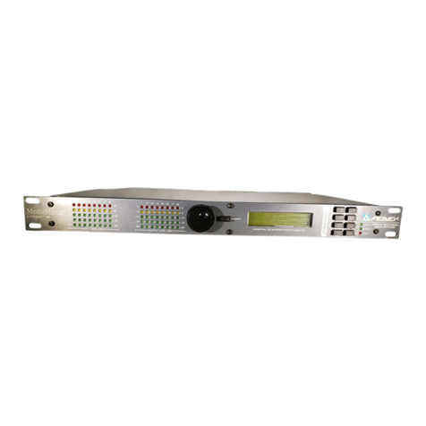
  9. Peavey MediaMatrix MM-8802 User manual

Peavey MediaMatrix MM-8802 User manual

MM™-8802
MediaMatrix®
Break-out-Box (BoB)
User Manual
Intended to alert the user to the presence of uninsulated “dangerous voltage” within the product’s
enclosure that may be of sufficient magnitude to constitute a risk of electric shock to persons.
Intended to alert the user of the presence of important operating and maintenance (servicing)
instructions in the literature accompanying the product.
CAUTION: Risk of electrical shock — DO NOT OPEN!
CAUTION: To reduce the risk of electric shock, do not remove cover. No user serviceable parts inside. Refer
servicing to qualified service personnel.
WARNING: To prevent electrical shock or fire hazard, do not expose this appliance to rain or moisture. Before
using this appliance, read the operating guide for further warnings.
Este símbolo tiene el propósito, de alertar al usuario de la presencia de “(voltaje) peligroso” sin ais-
lamiento dentro de la caja del producto y que puede tener una magnitud suficiente como para constituir
riesgo de descarga eléctrica.
Este símbolo tiene el propósito de alertar al usario de la presencia de instruccones importantes sobre la
operación y mantenimiento en la información que viene con el producto.
PRECAUCION: Riesgo de descarga eléctrica ¡NO ABRIR!
PRECAUCION: Para disminuír el riesgo de descarga eléctrica, no abra la cubierta. No hay piezas útiles dentro.
Deje todo mantenimiento en manos del personal técnico cualificado.
ADVERTENCIA: Para evitar descargas eléctricas o peligro de incendio, no deje expuesto a la lluvia o humedad
este aparato Antes de usar este aparato, Iea más advertencias en la guía de operación.
Ce symbole est utilisé dans ce manuel pour indiquer à l’utilisateur la présence d’une tension dangereuse
pouvant être d’amplitude suffisante pour constituer un risque de choc électrique.
Ce symbole est utilisé dans ce manuel pour indiquer à l’utilisateur qu’il ou qu’elle trouvera d’importantes
instructions concernant l’utilisation et l’entretien de l’appareil dans le paragraphe signalé.
ATTENTION: Risques de choc électrique — NE PAS OUVRIR!
ATTENTION: Afin de réduire le risque de choc électrique, ne pas enlever le couvercle. Il ne se trouve à l’intérieur
aucune pièce pouvant être reparée par l’utilisateur. Confiez I’entretien et la réparation de l’appareil à un réparateur
Peavey agréé.
AVERTISSEMENT: Afin de prévenir les risques de décharge électrique ou de feu, n’exposez pas cet appareil à la
pluie ou à l’humidité. Avant d’utiliser cet appareil, lisez attentivement les avertissements supplémentaires de ce
manuel.
Dieses Symbol soll den Anwender vor unisolierten gefährlichen Spannungen innerhalb des Gehäuses
warnen, die von Ausreichender Stärke sind, um einen elektrischen Schlag verursachen zu können.
Dieses Symbol soll den Benutzer auf wichtige Instruktionen in der Bedienungsanleitung aufmerksam
machen, die Handhabung und Wartung des Produkts betreffen.
VORSICHT: Risiko — Elektrischer Schlag! Nicht öffnen!
VORSICHT: Um das Risiko eines elektrischen Schlages zu vermeiden, nicht die Abdeckung enfernen. Es befinden
sich keine Teile darin, die vom Anwender repariert werden könnten. Reparaturen nur von qualifiziertem
Fachpersonal durchführen lassen.
ACHTUNG: Um einen elektrischen Schlag oder Feuergefahr zu vermeiden, sollte dieses Gerät nicht dem Regen
oder Feuchtigkeit ausgesetzt werden. Vor Inbetriebnahme unbedingt die Bedienungsanleitung lesen.
GENERAL CAUTIONS AND WARNINGS!
To prevent electrical shock or potential fire hazards, do not expose the MM™-8802 to moisture or rain.
Before usin this product, read the user manuals for further warnin s and cautions.
The followin cautions should be carefully observed when installin , wirin or usin this product:
DO NOT use any other power supply or cable other than the one provided with this unit.
DO NOT use solvents or other cleaners to clean the unit. Basic external care requires only a damp
cloth. Disconnect the power supply cord before cleanin .
Take care when removin the top cover of the unit. Adjustment of internal components should be
performed by qualified technical personnel only! Remove the power cable prior to openin the
unit.
Read all safety and installation instructions and retain all documentation for further reference.
The MM-8802 should be installed so that its mountin position does not interfere with proper ven-
tilation.
This product should not be installed or placed near a source of heat.
Power supply cords and associated connectors should be unplu ed from the power source when
the unit is not used for lon periods of time, or will be stored.
If this product is to be mounted in an equipment rack, install rear support if required by the rack
manufacturer.
Care should be taken to ensure that the installation is clear of possible sources of contamination.
Make sure that the product’s ventilation openin s are not exposed to possible sources of liquid,
ases, or other contaminants.
This product should be inspected by a qualified service technician if the power supply cord or con-
nector has been dama ed, if the unit has been dropped, or if a forei n substance has ained access
to the interior electronic and electrical components.
The information contained in this manual is subject to chan e without notice. Peavey Electronics is not liable
for improper installation or confi uration. The information contained herein is intended only as an aid to
qualified personnel in the desi n, installation and maintenance of en ineered audio systems. The installin
contractor or end user is ultimately responsible for the successful implementation of these systems.
All creative content, includin but not limited to, specifications, layout desi n, artwork, photo raphy, draw-
in s, illustrations and lo os are Copyri ht © 2001 Peavey Electronics Corporation, all ri hts reserved, except
where noted. MediaMatrix®; MM™; the stylized Delta lo o; the MediaMatrix computer lo o; the "fast forward",
stylized Peavey lo o and the Architectural Acoustics brand name are re istered trademarks of Peavey
Electronics. Un-authorized duplication or distribution is prohibited by law. This manual was desi ned, writ-
ten, formatted, pre-press and printed in Meridian, Mississippi, USA. 2001.
Manual by WR.
Page 4 http: aa.peavey.com copyright 2001 All Rights Reserved
Caution! 6
Thank You! 7
What’s In The Box? 7
7
Description 8
Features 9
Assumptions 9
Installation 10
11
Input Devices 15
Rotary Control 31
External DC Power Supply 32
Lo ic Output Ports 33
Usin Lo ic Output Ports with LEDs 34
Usin Lo ic Output Ports With Hi h Current Devices 35
Hardware vs. Software Devices 12
Basic MediaMatrix®Connections 26
Control Volta e (CV) Input Ports 29
Control Volta e (CV) Connection Examples
Gain Structure 16
MM-8802 Software Control Device 20-21
MediaMatrix Software Input & Output Wirin Block Devices 22-23
Panel Features 24-25
The Test View 13
Audio Inputs 14
MM™-8802 User Manual
Table of Contents
Software Devices for Control Ports 36
Calibratin CV Inputs 37
Fault Contacts 38
Switch 30
Audio 27
External Control 28
Settin Full-Scale Input Sensitivity 17
MediaMatrix®, Meters & the MM-8802 18
Settin Full-Scale Output Drive 19
Adjustin Full-Scale Settin s in Le acy Mode 19
Si nal Flow
Products
Page 5Peavey Electronics Corporation
Table Of Contents
The Le acy Connection 39
Cate ory 5 (CAT 5) Cablin & Terminations 40-41
Technical Support 42
Warranty Re istration 42
Frequently Asked Questions (FAQ) 43
Specifications 44-45
Warranty Statement 46
The di ital audio transport devices and their control panels (Fig. 2) 12
Recommended Test View Confi uration (Fig. 3) 13
MM-8802 Control Device Features 20-21
Input & Output Wirin Block Device Features 22-23
Panel Features 24-25
Basic MediaMatrix®Connections 26
Illustrations
Audio Termination, Step by Step 27
Control Volta e (CV) Input Connections (Fig. 4) 29
Control Volta e (CV) Circuit (Fig. 5) 29
Control Volta e (CV) Input Switch Interface Example 30
Control Volta e (CV) Rotary Control Interface Example 31
External DC Power Supply Interface Example 32
Lo ic Output Port Connections (Fig. 6) 33
Lo ic Output Circuit (Fig. 7) 33
Usin Lo ic Ports & LEDs 34
Usin Lo ic Ports with Hi h Current Devices 35
CV Input Values & TTL Lo ic Output To le Buttons (Fig. 8) 36
CV Input Calibration Controls (Fig. 9) 36
TTL Lo ic Output connections and control buttons (Fig. 10) 36
Calibratin Control Volta e (CV) Inputs, Step by Step 37
Fault Contacts 38
Cate ory 5 (CAT 5) Wirin Details 41
DIP Switch Confi uration 19
Input Devices 15
Index 47-49
The MM™-8802 control block components and the physical hardware (Fig. 1) 12
Si nal Flow& Meters 11, 18
Page 6 http: aa.peavey.com copyright 2001 All Rights Reserved
CAUTION!
The MM-8802 is desi ned to work in conjunction with MediaMatrix®brand products. The di ital interface between the MM-
8802 and the MediaMatrix product is a crucial link in the successful implementation of your system. Use only hi h quality
Cate ory 5 cables when usin the MM-8802 with the MM DSP-RJ DPU card or the X-Frame™88 di ital processor. If you are
usin the le acy MM DSP DPU card, you must use the Peavey 9-pin DB-9 le acy cable only. The MM-8802 will not perform
properly if other 9-pin cables are used with the le acy products. Installin the MM-8802 with inferior or improper cables
could also cause dama e to the components in your sound system. Peavey will not be held liable for dama e to components or
transducers caused by improper use of interface cablin when usin MediaMatrix products.
Like other electronic systems, the infrastructure is critical for implementin lar e systems that transverse lar e distances. It is
important that your conduit systems, wire plants and connector complement are properly desi ned and installed. The wirin
and cablin systems should be thorou hly inspected and each run certified to pass the specified bandwidth prior to the instal-
lation of any active electronic component. Failure to implement proper cablin systems may cause your system to perform at
inferior levels.
Several associated products are required to complete a workin system usin the MM-8802. This manual frequently makes
reference to these products, but does not provide specific confi uration or installation information on them. Please refer to the
manuals for these products for information. Every product, both Peavey products and third party devices, must be properly
installed for the MM-8802 to operate in accordance with its published specification.
This product is fan-cooled with an exhaust fan on one side of the unit. Air is drawn inward from the other side. Do not block
the fan or any vents when installin this product. Proper coolin is essential to maintain proper operation and lon -term sta-
bility in this product. Install this product in EIA approved equipment racks only.
The information contained in this manual is subject to chan e without notice. Peavey Electronics is not liable for improper
installation or confi uration. The information contained herein is intended only as an aid to qualified personnel in the desi n,
installation and maintenance of en ineered audio systems. The installin contractor or end user is ultimately responsible for
the successful implementation of these systems.
The illustrations, drawin s and renderin s contained herein are NOT drawn to scale.
MM™-8802 User Manual
Welcome
Page 7Peavey Electronics Corporation
Thank You! Thank you for purchasin the MM™-8802 Break-out-Box or "BoB" for
MediaMatrix®di ital audio processin systems. The MM-8802 represents
the latest in state-of-the-art audio technolo y for fixed commercial audio
installations.
This manual was written to provide as much information as possible for
your new Peavey Architectural Acoustics product. It is our sincere desire
that you enjoy your purchase.
We feel that the best way to fully enjoy any purchase is to have an in-depth
understandin of the product’s features, functionality and performance char-
acteristics. We hope that this manual, alon with the manuals of our other
products, will provide this. If you require additional information that this
manual does not provide, please let us know. We are always lookin for bet-
ter ways to provide information about our products, and your input is
always appreciated.
If you have a comment about this manual, or would like to make a su es-
tion, please write to: Peavey Electronics Corp., Architectural Acoustics
Division, 711 A St., Meridian, MS 39301. Thank you a ain for usin Peavey!
What’s In The Box? The MM-8802 is packa ed in a sin le container. This container includes the
followin items:
1- MM-8802 Break-out-Box
1- IEC removable power supply line cord
(120VAC Domestic, 230VAC Export)
17- 3-screw Euro connectors*
2- 16-screw Euro connectors*
1- User Manual/Literature Packa e
1- Warranty Card
* These items are shipped installed on the MM-8802
If any of these items are missin , please contact your authorized Peavey
Architectural Acoustics contractor/dealer or the factory.
Products This manual covers the MM-8802 Break-out Box for MediaMatrix brand
products. The MM-8802 replaces the followin products:
MM-8830 Break-out-Box
MM-8840 Break-out-Box
MM-8848 Break-out-Box
The functionality provided by these le acy products is provided in the new
MM-8802, as well as many additional features and improved performance.
The MM-8802 is desi ned to be seamlessly inte rated with these products
and all MediaMatrix brand products.
MM™-8802 User Manual
Page 8 http: aa.peavey.com copyright 2001 All Rights Reserved
Description Followin on the heels of the ori inal MM-8800 Series products, the new
MM-8802 represents a si nificant improvement in audio performance, con-
trol functionality, monitorin , installation and cost. New advances in pro-
cessin and control technolo y make the MM-8802 the most reliable break-
out-box yet. The MM-8802 is desi ned to work seamlessly with all
MediaMatrix®and Architectural Acoustics®products. We are confident that
you will find the MM-8802, as well as other Architectural Acoustics prod-
ucts to be of the hi hest quality available.
The MM-8802 features a new sin le rack space packa e with several new
and improved features. This 24-bit audio product provides the very best
audio performance for MediaMatrix systems and a lar e array of control fea-
tures, monitorin and installation benefits. Usin state-of-the-art technolo-
y and advanced audio converters make the MM-8802 one of best values in
the commercial di ital audio market.
Desi ned for hi h end, fixed-install en ineered audio systems, the MM-8802
includes functionality desi ned for the system desi ner. These new features
make lar e scale system desi n, en ineerin and implementation easier than
ever. Amon the many features included with the MM-8802 are control
lo ic inputs, lo ic outputs, fault monitorin , CAT 5 DSP interface and a new
sin le space packa e featurin front panel meterin of audio inputs and out-
puts. New software control of analo circuitry makes ain mana ement eas-
ier and puts control of analo , as well as di ital audio, on the desktop.
With a state-of-the-art, studio rade analo section and 24-bit converters,
the MM-8802 provides an extremely hi h performance vs. cost ratio. With
inte ral control ports and support for the le acy MediaMatrix interface, the
MM-8802 is a solid, feature-loaded value.
Features
ssumptions
Sin le EIA rack space packa e
Forced air coolin
24-bit converters
Universal sample rate support
Ei ht line level audio inputs (mic or line capable)
Software selectable input sensitivity
Ei ht line level audio outputs
Software selectable full-scale output level
Ei ht Control Volta e (CV) control inputs
Ei ht TTL lo ic outputs
Independent fault monitorin dry contacts
Front panel audio meterin
Front panel status monitorin
Cate ory 5 cablin interface
New 50' cable distance
Le acy cable support
Universal power supply
The MM™-8802 is a very powerful tool. Ease of use, external control
options, and a powerful interface make the MM-8802/MediaMatrix®
combination perfect for any application, includin :
- Theme Parks
- Presentation Rooms
- Board Rooms
- Houses of Worship
- Courtrooms
- Auditorium/Cafetorium
- Lecture Hall Sound Reinforcement
- Meetin Rooms
- Convention Centers
- Stadiums
- Arenas
- Pa in
- Back round Music
- Retail Spaces
- Restaurants
- Live Performance Venues
The new features, performance advanta es and functionality included
in the MM-8802 make this product one of the best audio values avail-
able. From simple X-Frame™systems with basic audio requirements, to
full blown, multiple-frame MediaMatrix systems, the MM-8802 is an
excellent choice.
The MM-8802 is desi ned for basic and advanced MediaMatrix sys-
tems. It is assumed that you have a workin knowled e of MediaMatrix
hardware and software, computers and basic Microsoft Windows navi-
ation. If you do not have this knowled e, please refer the confi ura-
tion and installation of this product to qualified personnel. For in-
depth information on MediaMatrix, refer to the online help.
Features
Page 9Peavey Electronics Corporation
Installation The MM-8802 is desi ned to be installed in commercial rade, EIA electron-
ic equipment racks only. Installin this unit in non-EIA racks or in other
confi urations is not recommended. Failure to install this product in the
proper enclosure may void your warranty.
The MM-8802 is forced-air cooled, and care should be taken not to block the
air intake or exhaust path. When installed in EIA racks, the MM-8802 can
be installed in adjacent rack spaces without additional ventin . However, it
is recommended that common sense be applied to lar e installations where
multiple units are mounted in a sin le rack. It is enerally accepted that a
ratio of one vent for every two MM-8802s is a ood rule of thumb that usual-
ly provides adequate performance. In installations where adverse conditions
exist, and room temperatures are likely to rise, additional vents should be
installed.
The MM-8802 can be installed into any EIA rack with an internal depth
clearance of 24" or more. This will allow plenty of space for the unit and its
associated wirin harness. When dressin off wirin harnesses, take care
with CAT 5 cables. Do not tie-wrap bundles of CAT 5 wire too ti htly.
Leave plenty of room for bends, allowin the cable to pro ress naturally from
the RJ-45 connector. Creatin ti htly wrapped CAT 5 wire bundles can
cause loose crimp joints and defective terminations.
To successfully install your new MM-8802, and perform the testin exam-
ples contained in this manual, you will need the followin components:
In MediaMatrix, the minimum confi uration consists of a sin le DPU pro-
cessin en ine (X-Frame or frame/DSP card combination), and I/O.
Dependin on your system, this may consist of several products. When
usin the MM-8802, at least one unit is required to confi ure the minimum
system. Of course, most systems will include more DPU products and mul-
tiple MM-8802s, but this is the most basic confi uration.
The use of hi h quality, network rade CAT 5 cables is required to success-
fully implement the MM-8802 with new MediaMatrix products. Please
refer to the section on CAT 5 cablin later in this manual.
MM™-8802 User Manual
Page 10 http: aa.peavey.com copyright 2001 All Rights Reserved
A MediaMatrix®X-Frame™, X-Frame 88, MiniFrame 108nt or 208nt, MM-
760nt, MM-960nt or MM-980nt Mainframe.
MWare™3.1.2, X-Frame 88 2.0 or later software.
PC monitor, mouse and keyboard. For use with the X-Frame products, a
separate personal computer runnin Windows®95, 98, ME, NT 4.0
w/SP6 or Windows 2000 Professional is required.
For frame-based MediaMatrix systems, you will need at least 1 MM DSP-
RJ or MM DSP DPU card.
Two CAT 5 cables are required for each MM-8802.
An audio source, power amplifier and loudspeaker.
•
•
•
•
•
•
Signal Flow
Page 11Peavey Electronics Corporation
Signal Flow
Si nal flow is the basis for all audio system desi n. You cannot desi n and implement inte rated audio systems without under-
standin the basics of si nal flow, and how audio is transported between components. It is essential to all aspects of installa-
tion and maintenance. With the MM™-8802, it is equally important. You should understand the various sta es of si nal flow
within the MediaMatrix®system to accurately and efficiently confi ure, adjust, control and maintain the system.
As with all MediaMatrix systems, audio is separated into several fundamental processes. First, there is analo audio, real-world
waveforms that are a part of our everyday lives. This is what we hear and speak. Then there is di ital audio. Code that repre-
sents “samples” of actual analo audio si nals. This we cannot hear. And there is the conversion process. Audio must be con-
verted from analo waveforms to di ital code and then converted a ain, back to analo for use in our acoustic world. Look
carefully at the illustration below.
In the above example, stereo audio from the CD player ets into and out of the MediaMatrix system via the MM-8802. First,
your CD player’s output is connected to the MM-8802’s input. The si nal then passes the MM-8802’s analo ain sta e and
ets converted to di ital audio via the analo to di ital converter (A/D). When the si nal is past, or “after” the A/D converter, it
is in the di ital domain. After the converter, it exits the MM-8802 via the TX side of the CAT 5 di ital interface cable and
enters the MediaMatrix DSP. The two audio channels, left and ri ht from the CD player are then “inside” the MediaMatrix di -
ital processin en ine or DPU. You use “wire” and audio “devices” to create any si nal flow you desire for your CD audio si nal.
You can split it, process it, mix it, switch it, squash it, loop it, delay it...whatever you need to do, you can do with MediaMatrix.
In this example, we have a stereo mixer, stereo compressor and stereo parametric EQ. The si nal exits the DPU at the BoB out-
put block. After the si nal is processed, it exits the MediaMatrix system and returns to the MM-8802 via the RX side of the
CAT 5 interface cable. It then hits another conversion sta e, this time a di ital to analo converter (D/A) where the di ital si -
nal data is returned to analo waveforms. It then oes throu h a final analo ain sta e then shows up at the output terminal of
the MM-8802. It is this terminal that ets connected to the next component in your audio system, most often, the power
amplifier. (NOTE: When usin the 9-pin le acy cable for interfacin the MM-8802, the TX and RX circuits are contained
within a sin le cable.) Notice that the MM-8802 has several software control panels attached to it. There is the master control
panel that includes all of the analo audio and external control interface functionality for the MM-8802. There are also control
panels attached to the input and output block within the MediaMatrix DPU. Understandin these control panels is vital to
ood MediaMatrix implementation.
Analog to Digital
Converter
“Inside” the MediaMatrix.
Digital audio domain.
The DSP
MM-8802 Break-out-Box
Analog
Gain Stage
Analog Control
Digital Control
Digital to Analog
Converter
Analog
Gain Stage
External
Control Ports
Output
Drive Level
Input
Sensitivity
Analog audio components
TX
INPUT OUTPUT
RX
MM™-8802 User Manual
Page 12 http: aa.peavey.com copyright 2001 All Rights Reserved
Hardware vs. Software Devices
The MM-8802 is an inte ration of physical hardware and software. In software, the MM-8802 is represented by several
“devices” within the MediaMatrix®MWare™application. These devices include the Control Block, the Input Block and the
Output Block. For proper operation of this product, a thorou h understandin of these devices is required.
There is a very basic relationship between the MM-8802 physical product and its accompanyin software devices. Of these
three devices, one is the “control panel” for the hardware. There are no physical controls on the MM-8802 itself, so all functions
for it are accessible only from its software based control panel (except for le acy mode DIP switches, see pa e 19). This control
panel can be found under the Input/Output section of the Device Menu. The fi ure below illustrates the relationship between
the MM-8802 and its software control device.
The second half to this equation is the audio transport. The concept of audio I/O is an extremely important part of confi urin
MediaMatrix systems. It is the “wire” that ets audio into, throu h and out of the system. Within MediaMatrix, this process is
represented by two I/O blocks with “nodes” on them. These represent the actual input and output points for the system. In the
fi ure below, you can see the two audio blocks. The one with the nodes on the ri ht of the block is an audio “input” block. In
other words, audio from the outside of the system enters the DSP at these nodes. The one with the nodes on the left side of the
block is an audio “output”. It is at this point where di ital audio exits the system. Each of these blocks also has its own control
panel. These control panels include level controls and mute buttons for the each audio channel in the di ital domain.
Fig. 1, The MM-8802 ontrol blo k omponents and the physi al hardware.
Fig. 2, The digital audio transport devi es and their ontrol panels.
Input Side of
Audio Path
Digital Input
Control Panel
Digital Output
Control Panel
Output Side of
Audio Path
Hardware & Software Basics
Page 13Peavey Electronics Corporation
The Test View
In order to properly use this manual, it is recommended that a basic MediaMatrix®view file be confi ured. This view file
should have a minimum number of components and should be confi ured to install and test a sin le MM™-8802. Eventually
however, your view will include many units, and should match exactly your specific system requirements. The followin fi ure
is a ood example of such a “test” file.
A ain, it is very important to understand the relationship between the MM-8802 hardware, the outside audio path and the di -
ital audio path within MediaMatrix. Audio enters and exits the MediaMatrix system at the wire blocks and travels within the
MediaMatrix system di itally. The wires represent this audio path within the MediaMatrix system.
Remember, the BoB Control Block includes only the analo audio controls for the MM-8802, while the wirin blocks include
the di ital audio controls. Both of these control sets are critical to the proper operation of your sound system. Refer to the si -
nal flow block dia ram on pa e 11 for details on this si nal flow.
Fig. 3, Re ommended Test View Configuration
BoB Control Block
MM-8802 Audio
Output Device
MM-8802 Audio
Input Device
Audio from the “outside”
enters the MediaMatrix
system here.
These wires carry
di ital audio within
the MediaMatrix
system
Audio to the “outside”
exits the MediaMatrix
system here.
MM™-8802 User Manual
Page 14 http: aa.peavey.com copyright 2001 All Rights Reserved
udio Inputs The MM-8802 includes functionality that supports a new modular input
architecture. This architecture provides the ability to confi ure the MM-
8802’s analo inputs for either microphone or line-level operation. Two
internal module bays provide connection to factory installed input modules.
These modules consist of the MM-Line 4, which provides four analo line
level inputs and the MM-Mic 4, which provides four analo microphone
level inputs. A total of two modules are installed at the factory on the MM-
8802. Which modules are installed is up to you!
-Line 4
The MM-Line 4 input card includes four line level inputs and installs into
slot 1 or slot 2 of the MM-8802 input section. The MM-Line 4 includes full
software control of input sensitivity and analo ain. It is possible to install
one or two MM-Line 4 modules into the MM-8802.
- ic 4
The MM-Mic 4 input card includes four mic or line level inputs and installs
into slot 1 or slot 2 of the MM-8802 input section. The MM-Mic 4 features
studio rade microphone preamplifiers, complete with software controllable
phantom power and ain controls for each channel. It is possible to install
one or two MM-Mic 4 modules into the MM-8802.
With these new modules, the MM-8802 can be confi ured in a variety of dif-
ferent ways.
• 8 line inputs, 8 line outputs
• 8 mic inputs, 8 line outputs
• 4 mic inputs, 4 line inputs, 8 line outputs
By makin the inputs modular, the MM-8802 provides even reater flexibili-
ty and makes for much more cost-effective system desi n.
Inputs
Page 15Peavey Electronics Corporation
Input Devices
When lookin at the rear panel of the MM™-8802, you can see which module is installed by notin the color of the input con-
nector header. The header for the MM-Line 4 is black, while the header for the MM-Mic 4 is reen. The MM-8802’s software
control module will indicate which card is installed by illuminatin either a “Mic” or “Line” LED on the software control device
in the MediaMatrix software. (See pa e 20). If the “None” LED on the software control module is illuminated, it means that
there is no input module present. At the time of this printin , there is no option for usin an MM-8802 without any input
modules installed. If this LED is illuminated, it may indicate an unsuccessful installation of the input module.
Input Connector Header
Input Channels 1-4
Shown installed with
-Line 4 input module
(Black header)
Input Connector Header
Input Channels 5-8
Shown installed with
- ic 4 input module
(Green header)
Software control panel showing a suc-
cessful installation of an -Line 4 in
the input bay for channels 1-4.
Software control panel showing a suc-
cessful installation of an - ic 4 in
the input bay for channels 5-8.
Software control panel showing an
unsuccessful installation OR absence of
any input module for channels 5-8.
MM™-8802 User Manual
Page 16 http: aa.peavey.com copyright 2000 All Rights Reserved
Gain Structure Gain structure is amon the most important, often debated and misunder-
stood topics in the audio industry. For years, en ineers have disa reed with
each other about proper levels, ain I/O, meters and other issues that affect
the way we work. When di ital audio came into the mainstream, the topic’s
confusion was only compounded, and today, few fully understand the inner
workin s of ain structure. This is true within MediaMatrix®as well.
Althou h this manual does not present an exhaustive discussion on the
topic, it is important to understand the basics of ain structure, and how it
relates specifically to the MM-8802.
When the MM-8802 was desi ned, several important issues re ardin the
ain structure of its input and output sections were carefully considered.
There were performance issues, interface, ease of use and compatibility
issues that played a bi part in how the product was eventually desi ned.
In order to provide support for the thousands of MediaMatrix systems
already installed, the MM-8802 was desi ned with a unique contrast of old
and new. Essentially, the MM-8802 operates in one of two modes, “New” or
“Le acy” mode. These modes of operation extend to many facets of the MM-
8802’s functionality, but most si nificantly to the mana ement of its ain
structure.
When runnin in New mode, the MM-8802 includes functionality that sup-
ports software control of all analo settin s when usin current (MWare™
V3.1.2 or X-Frame™88 V2.0, or hi her) software. When runnin in Le acy
mode, that is, systems that are runnin older software, the adjustments of
Full-Scale Input Sensitivity and Full-Scale Output Drive levels are adjustable
from internal DIP switches. In this mode, the MM-8802 acts just like a le a-
cy BoB.
The le acy BoB models (MM-8830, MM-8840, MM-8848) did not include
support for software-based analo ain control. The only adjustments that
could be made were by internal jumpers for Full-Scale Input Sensitivity and
Full-Scale Output Drive level. And, because real-world conditions prevent a
universal standard, it was possible that the factory settin s would not be
appropriate for many projects. The likelihood was that, sooner or later, a
contractor would have to open the unit to adjust the analo settin s.
It is very important to understand that it is the software that determines
what mode the MM-8802 is operatin in, NOT the interface connector. The
new software includes support for control of the Full-Scale Input Sensitivity
and Full-Scale Output Drive settin s directly from the control panel as well
as input and output analo ain (trim). When these software controls are
available, all internal hardware switches are bypassed.
The software controls are explained on pa e 21. For le acy operation, you
will need to use the MM-8802’s internal DIP switches to adjust analo Full-
Scale Input Sensitivity and Full-Scale Output Drive levels.
Gain Structure
Page 17Peavey Electronics Corp
To fully understand how MediaMatrix®ain structure works, you should have a clear, hi h level view of how the Full-Scale
Input Sensitivity and Full-Scale Output Drive settin s relate to the front panel and software-based audio meters.
First and foremost, it is important to understand what the levels mean. The Full-Scale Input Sensitivity and Full-Scale Output
Drive settin s refer to separate analo circuits within the MM™-8802. These circuits are in addition to the fully adjustable ana-
lo input and output ain sta es. Both the Full-Scale Input Sensitivity and Full-Scale Output feature four user-definable set-
tin s. These settin s represent MAXIMUM (Full-Scale) levels, NOT nominal settin s. Keep this in mind as we pro ress.
In a di ital system, 0 dB indicates the “top” of the useable dynamic ran e, just below full-scale. For the inputs, full-scale indi-
cates the maximum level BEFORE converter clippin . On the front panel input meter, 0 dB has been calibrated to be <1 dB
below full-scale. Anythin over this level is clippin , or in di ital parlance, an “OVER”. Remember that the front panel input
meter is in the di ital domain, just after the analo to di ital (A/D) converter. The position of the Full-Scale Input Sensitivity
switch determines how much analo input si nal is required to et the front panel input meter to read 0 dB. Or, in other
words, to et the A/D converter to full-scale maximum input level.
The MM-8802 typically provides reater than 105 dB of dynamic ran e. This is the ran e of 100%, clean audio above the pub-
lished noise floor, and below the threshold of converter clippin (Full-Scale). The adjustable sensitivity switches simply “shift”
this dynamic ran e upwards or downwards before the si nal ets into the MediaMatrix DPU. This is done primarily to accom-
modate the connection of third party components and to match source output levels. The settin of the Full-Scale Input
Sensitivity will determine what level is required to drive the A/D converter to full-scale and illuminate the 0 dB front panel
input meter. For example, if +18 dBu is selected, then it will take +18 dBu of level to et to a 0 dB readin (full-scale A/D) on the
front panel input meter.
The settin in the Full-Scale Input Sensitivity dialo box will determine how the front panel input meters display audio levels
comin into the MM-8802. It is very important that these switches be set correctly. For example, if you know that the nomi-
nal levels of your system are oin to be around 0 dBu, and you want to monitor peak levels 12 dB above that, then you will
want to use the +18 dBu settin for the Full-Scale Input Sensitivity. This will allow the front panel meter to display +18 dBu at
the 0 dB LED. Your 12 dB headroom level in this case would show up at approximately -6 dB on the meter. In order to et the
maximum performance from the analo input sta e of the MM-8802, it is recommended that your Full-Scale Input Sensitivity
settin s be properly matched to the audio source and your headroom requirements.
What we are lookin at so far is front panel meterin . Remember this.....the settin of the Full-Scale Input Sensitivity switch
will always equal the 0 dB LED on the front panel input meter. This is the full-scale (maximum) level before A/D converter
clippin . So, how does this relate to the meters inside of MediaMatrix? Read on.....
Full-Scale Input Sensitivity set at +18 dBu
( aximum level at A/D converter)
Analog Input +18 dBu = Full Scale
Full Scale = 0 dBu eter
Front Panel Input eter
Setting Full-Scale Input Sensitivity
The key to understandin how the front panel and software meters relate is in the si nal flow. The levels at the BoB inputs and
outputs of the view file are the same levels displayed on the front panel meters, althou h they are calibrated differently. Once
the si nal is processed, di ital audio levels inside the DPU should be monitored exclusively within the view file usin software
meters. This is because there is an additional 12 dB of headroom, or ain, available exclusively within the DPU. This additional
ain cannot be displayed on the front panel meters. Before the si nal leaves the DPU at the BoB output block, it should be
attenuated back to full-scale converter level, or lower, to avoid clippin the D/A converter.
Refer to the above example. The Full-Scale Input Sensitivity switch is set for +18 dBu and a +18 dBu si nal is comin into the
MM-8802 (0 dB, or full-scale, on the front panel input meter). The first software meter, placed at the view file input block, will
indicate this level as +23.0 dB peak. The +23.0 dB represents the full-scale peak level, measured inside the DPU. Inside the
DPU, there is an additional 12 dB of headroom available for EQ, summin , etc. This headroom level is represented by a 12 dB
boost at the first Level control and the peak meter connected to it indicatin +35.0 dB (max DPU level). The si nal is then
attenuated by the second Level control to avoid clippin the MM-8802 and its peak meter a ain shows +23.0 dB. This si nal
level will be output via the BoB output block, and returned to the MM-8802 at full-scale. The front panel output meter will
display 0 dB, re ardless of the position of the Full-Scale Output Drive switches.
This +23.0 dBu level represents 0 dB on the front panel meters. Remember, the +23.0 dB DPU level is always the maximum full-
scale level that can be received by, or sent to the MM-8802. Anythin above +23.0 dB (DPU level) that is sent to the BoB out-
put block, and thus, to the MM-8802’s D/A will be clipped. The additional 12 dB of headroom is only available within the DPU.
MM™-8802 User Manual
Page 18 http: aa.peavey.com copyright 2000 All Rights Reserved
MediaMatrix®, Meters & the MM-8802
Inside the DPU audio levels are represented by software based meters that can be placed into the si nal flow at any sta e. They
can also be found within certain devices and can be confi ured as input or output meters. These meters include a bar- raph
display for quick visual reference. However, the more accurate way to monitor levels is by usin the small text display included
with each meter. This display will ive you exact readin s with much finer resolution than the bar- raph display.
It is very important to understand that the software meters display actual levels inside the di ital domain (DPU). Even thou h
the front panel meters are in the di ital domain, they can only display the di ital si nal immediately after the A/D and before
the D/A converters. In the view file, this same si nal shows up at the BoB input and output blocks. Once the si nal is
processed, split or distributed by other audio devices, the only way to accurately meter the si nal is by placin software meters
within the view file si nal flow. The relationship of the hardware and software meters is shown in the followin illustration.
(See pa es 20-21 for details on software controls.)
Analog to Digital
Converter
Front Panel
Input Meters Full-Scale = 0 dB
(Full-Scale In) (Gain/Headroom)
MM-8802
DPU
(Full-Scale Out)
Front Panel
Output Meters
Analog
Gain Stage
Digital Control
Digital to Analog
Converter
Analog
Gain Stage
Output
Drive Level
Input
Sensitivity
TX
INPUT OUTPUT
RX
Gain Structure
Page 19Peavey Electronics Corporation
djusting Full-Scale Input Sensitivity and Output Drive Settings in Legacy Mode
If the MM-8802 is operatin with current software, ( MWare™ V3.1.2 or X-Frame™88 V2.0) these settin s are adjustable from
the software controls. If the MM-8802 is connected to a MediaMatrix system of an earlier vinta e, then these software
controls, as well as all other analo controls, are disabled. In this case, the MM-8802 operates in “le acy” mode, and acts just
like an older BoB. In le acy mode, you must adjust the analo Full-Scale Input Sensitivity and Full-Scale Output Drive level
with the DIP switches. The illustration below shows the layout of the MM-8802’s internal DIP switches. These switches per-
form the same function as the software based Full-Scale Input Sensitivity and Full-Scale Output Drive controls shown on pa e
21. The ran e of adjustment is the same, and there is a switch for each input and output channel.
The default settin s provide for a 12 dB loss throu h the MM-8802. This is done intentionally to maintain compatibility with
older BoBs. The illustration below shows the DIP switches as they appear on the circuit board at the factory default settin s.
NOTE: If you are running new software and can see the Full-Scale Input Sensitivity and Full-Scale Output Drive con-
trols, as shown on page 21, then the DIP switches are NOT active. Software control will override these switches.
The DIP switches are located on the main circuit board inside the MM-8802. To ain access, remove only the top cover of the
unit. The switches are located on the center of the circuit board, adjacent to the input boards. It will be obvious, since these
DIP switches are the only DIP switches used on the MM-8802’s main board. There are four 8-position DIP assemblies. Each
channel is controlled by two switches, each with an “up” and “down” position. If the switch is located in the center of its trav-
el, it is not adjusted correctly. Just below the switches is a printed key of the switch positions and their relative levels. The key
applies to all channels.
Front
Rear
Adjustment of the DIP switches requires access to the inside of the -8802. It is highly recommended that this proce-
dure be performed ONLY by qualified service personnel. Remove the power cable prior to removing the cover. There
are dangerous voltages present inside the unit, as well as static sensitive components. Damage to the -8802’s inter-
nal components caused by unqualified persons performing this procedure will void the warranty.
WARNING!!
Full-Scale Output Drive
What about the outputs? The outputs are easy....just set the drive level you want. The full-scale DPU levels will be available at
the output of the MM™-8802 at your choice of analo levels, so you don’t take a performance loss if you need a lower output
level to match the input sensitivity of your power amplifier. Likewise, if you use the MM-8802 to drive line-level audio over
lon distances and need to use a hi her drive level, you still et the same, full-scale performance. Also, the settin of the Full-
Scale Output Drive level does not affect the levels comin into the MM-8802 or the levels inside the DPU.
In our previous example, we would be ettin +23.0 dB at the input to the MM-8802’s di ital to analo (D/A) converter. This is
full-scale, as determined by the input, and the DPU processin . The actual analo audio level at the MM-8802’s output is deter-
mined by the position of the Full-Scale Output switch. Remember, it doesn’t matter which output settin you choose, you still
et full-scale performance. Just like the input side, these switches allow you to “shift” your dynamic ran e upward or down-
ward to match your application. If you choose a +6 dBu settin , then the full-scale analo output level will be + 6.0 dBu. As in
our example, a +18.0 dBu settin would ive you unity ain and the output level of the MM-8802 would be exactly the same as
the input level of +18.0 dBu.
MM™-8802 User Manual
Page 20 http: aa.peavey.com copyright 2001 All Rights Reserved
MM-8802 Control Device Features
SA PLE RATE This control indicates the active com-
piled sample rate as determined by the view file. The
options are 32k, 44.1k or 48 kHz.
LOCKED LED This LED will illuminate when the MM-
8802 has been successfully locked with the MM DSP (RJ)
DPU card.
INPUT TYPE LEDs indicate the type of input card pres-
ent. “Line” indicates the presence of the MM-Line 4. “Mic”
indicates the presence of the MM-Mic 4. “None” indicates
that no input card is installed, or there is an error.
LINE INPUT GAIN This control includes the rotary knob
and the correspondin indicator above it. This controls the
MM-Line 4’s analo line level input ain sta e, before the
A/D converter. The ran e is -95.5 to +30.5 dB, (+/- 0.5 dB).
PHANTO This switch to les +48 Volts DC of phantom
power at the input terminals of the MM-Mic 4 input mod-
ule.
IC INPUT GAIN This control includes the rotary knob
and the correspondin indicator above it. This controls the
MM-Mic 4’s analo mic level input ain sta e, before the
A/D converter. The ran e is 0 to +63 dB, (+/- 3 dB).
OUTPUT GAIN This control includes the rotary knob and
the correspondin indicator above it. This controls the ana-
lo output sta e, after the D/A converter. The ran e is -95.5
to +30.5 dB, (+/- 0.5 dB).
TTL OUT This is a “maintained” ON/OFF button. In the
down (ON) position, a positive control volta e is output on
the correspondin TTL lo ic output port.
CV INPUTS Displays the value of the control volta e
input when an external device is connected to the corre-
spondin CV port. This is a control and may be estured
manually to simulate the action of an external control (only
when there is no external connection). The ran e is 0-100.
CV CAL DIALOG BLOCK Double clickin (Edit Mode)
or sin le clickin (Control Mode) on this box will open the
CV Calibration Dialo Box. (See opposite pa e.) This box
is closed by clickin on the “X” in the upper ri ht hand cor-
ner in any mode.
TROUBLE LED This LED will illuminate when any type
of fault is present in the MM-8802 or its communications
link.
CO ERROR LED This LED will illuminate when
there is a communications error between the MM-8802
and the MM DSP (RJ) DPU card.
FULL-SCALE SENSITIVITY BLOCK When clicked
upon, this block opens an additional window for input sen-
sitivity. See opposite pa e.
FULL-SCALE OUTPUT BLOCK When clicked upon,
this block opens an additional window for analo output
ain control. See opposite pa e.
1
2
3
11
12
13
14
4
5
7
8
10
9
1.
2.
3.
4.
5.
6.
7.
8.
9.
10.
11.
12.
13.
14.
6

Other Peavey Computer Hardware manuals

Peavey Miniframe 108nt User manual

Peavey

Peavey Miniframe 108nt User manual

Peavey AddVerb User manual

Peavey

Peavey AddVerb User manual

Peavey DEP 800 User manual

Peavey

Peavey DEP 800 User manual

Peavey Vocal 100 User manual

Peavey

Peavey Vocal 100 User manual

Peavey AddVerb II User manual

Peavey

Peavey AddVerb II User manual

Peavey kosmos Pro User manual

Peavey

Peavey kosmos Pro User manual

Peavey IDL 1000 User manual

Peavey

Peavey IDL 1000 User manual

Peavey DTH 118 User manual

Peavey

Peavey DTH 118 User manual

Peavey Mediamatrix MM-740 Mainframe User manual

Peavey

Peavey Mediamatrix MM-740 Mainframe User manual

Peavey MediaMatrix MM-900NT SERIES User manual

Peavey

Peavey MediaMatrix MM-900NT SERIES User manual

Peavey FMT-1 User manual

Peavey

Peavey FMT-1 User manual

Peavey MIDI Master II User manual

Peavey

Peavey MIDI Master II User manual

Peavey CEQ 28R User manual

Peavey

Peavey CEQ 28R User manual

Peavey GEN-S User manual

Peavey

Peavey GEN-S User manual

Peavey VSX 26 User manual

Peavey

Peavey VSX 26 User manual

Peavey Freq-Out User manual

Peavey

Peavey Freq-Out User manual

Peavey MPT-S1 User manual

Peavey

Peavey MPT-S1 User manual

Peavey MediaMatrix MM-760nt User manual

Peavey

Peavey MediaMatrix MM-760nt User manual

Peavey DEP 3.2S User manual

Peavey

Peavey DEP 3.2S User manual

Peavey Kosmos User manual

Peavey

Peavey Kosmos User manual

Peavey MIDI Librarian User manual

Peavey

Peavey MIDI Librarian User manual

Peavey MediaMatrix X-Frame 88 User manual

Peavey

Peavey MediaMatrix X-Frame 88 User manual

Peavey DPM 4 User manual

Peavey

Peavey DPM 4 User manual

Peavey MediaMatrix MM-950 User manual

Peavey

Peavey MediaMatrix MM-950 User manual

Popular Computer Hardware manuals by other brands

Ublox EVK-JODY-W163 quick start

Ublox

Ublox EVK-JODY-W163 quick start

Global Sources BTD-0140 user manual

Global Sources

Global Sources BTD-0140 user manual

digi-tech STUDIOVOCALISTEX manual

digi-tech

digi-tech STUDIOVOCALISTEX manual

A4Tech RN-10A user manual

A4Tech

A4Tech RN-10A user manual

Corsair VENGEANCE AIRFLOW quick start guide

Corsair

Corsair VENGEANCE AIRFLOW quick start guide

Corsair Hydro Series manual

Corsair

Corsair Hydro Series manual

KeriSystems KeriGen DuoPak user manual

KeriSystems

KeriSystems KeriGen DuoPak user manual

SMART-AVI SM-EHD quick start guide

SMART-AVI

SMART-AVI SM-EHD quick start guide

AirLive AirVideo-100v2 user manual

AirLive

AirLive AirVideo-100v2 user manual

BIG TREE TECH Octopus MAX EZ user manual

BIG TREE TECH

BIG TREE TECH Octopus MAX EZ user manual

Hamilton/Buhl HB123 user guide

Hamilton/Buhl

Hamilton/Buhl HB123 user guide

T'nB BUSB25 Instructions for use

T'nB

T'nB BUSB25 Instructions for use

BOSSCO AD-8 owner's manual

BOSSCO

BOSSCO AD-8 owner's manual

Elmo HS520 User and programming manual

Elmo

Elmo HS520 User and programming manual

Ublox XPLR-HPG-2 user guide

Ublox

Ublox XPLR-HPG-2 user guide

Ebmpapst S8E630-AN01-01 operating instructions

Ebmpapst

Ebmpapst S8E630-AN01-01 operating instructions

Global American Inc. 330827 user manual

Global American Inc.

Global American Inc. 330827 user manual

IDTECH IDP-05-L1 user manual

IDTECH

IDTECH IDP-05-L1 user manual

manuals.online logo
manuals.online logoBrands
  • About & Mission
  • Contact us
  • Privacy Policy
  • Terms and Conditions

Copyright 2025 Manuals.Online. All Rights Reserved.