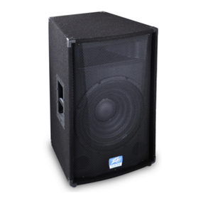
Peavey PR 10P User manual

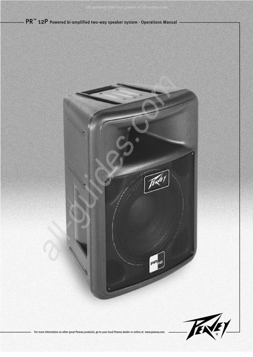
PR™10P Powered bi-amplified two-way speaker system · Operations Manual
For more information on other great Peavey products, go to your local Peavey dealer or online at www.peavey.com.

2
Intended to alert the user to the presence of uninsulated “dangerous voltage” within the product’s
enclosure that may be of sufficient magnitude to constitute a ris of electric shoc to persons.
Intended to alert the user of the presence of important operating and maintenance (servicing)
instructions in the literature accompanying the product.
CCAAUUIIOONN::Ris of electrical shoc — DO NOT OPEN!
CCAAUUIIOONN::To reduce the ris of electric shoc , do not remove cover. No user serviceable parts inside.
Refer servicing to qualified service personnel.
WWAARRNNIINNGG::To prevent electrical shoc or fire hazard, do not expose this appliance to rain or moisture.
Before using this appliance, read the operating guide for further warnings.
Este símbolo tiene el propósito, de alertar al usuario de la presencia de “(voltaje) peligroso” sin
aislamiento dentro de la caja del producto y que puede tener una magnitud suficiente como para
constituir riesgo de descarga eléctrica.
Este símbolo tiene el propósito de alertar al usario de la presencia de instruccones importantes sobre la
operación y mantenimiento en la información que viene con el producto.
PPRREECCAAUUCCIIOONN::Riesgo de descarga eléctrica ¡NO ABRIR!
PPRREECCAAUUCCIIOONN::Para disminuír el riesgo de descarga eléctrica, no abra la cubierta. No hay piezas útiles
dentro. Deje todo mantenimiento en manos del personal técnico cualificado.
AADDVVEERREENNCCIIAA::Para evitar descargas eléctricas o peligro de incendio, no deje expuesto a la lluvia o
humedad este aparato Antes de usar este aparato, Iea más advertencias en la guía de operación.
Ce symbole est utilisé dans ce manuel pour indiquer à l’utilisateur la présence d’une tension dangereuse
pouvant être d’amplitude suffisante pour constituer un risque de choc électrique.
Ce symbole est utilisé dans ce manuel pour indiquer à l’utilisateur qu’il ou qu’elle trouvera d’importantes
instructions concernant l’utilisation et l’entretien de l’appareil dans le paragraphe signalé.
AAEENNIIOONN::Risques de choc électrique — NE PAS OUVRIR!
AAEENNIIOONN::Afin de réduire le risque de choc électrique, ne pas enlever le couvercle. Il ne se trouve à
l’intérieur aucune pièce pouvant être reparée par l’utilisateur. Confiez I’entretien et la réparation de
l’appareil à un réparateur Peavey agréé.
AAVVEERRIISSSSEEMMEENN: Afin de prévenir les risques de décharge électrique ou de feu, n’exposez pas cet
appareil à la pluie ou à l’humidité. Avant d’utiliser cet appareil, lisez attentivement les avertissements
supplémentaires de ce manuel.
Dieses Symbol soll den Anwender vor unisolierten gefährlichen Spannungen innerhalb des Gehäuses
warnen, die von Ausreichender Stär e sind, um einen ele trischen Schlag verursachen zu önnen.
Dieses Symbol soll den Benutzer auf wichtige Instru tionen in der Bedienungsanleitung aufmer sam
machen, die Handhabung und Wartung des Produ ts betreffen.
VVOORRSSIICCHH:: Risi o — Ele trischer Schlag! Nicht öffnen!
VVOORRSSIICCHH:: Um das Risi o eines ele trischen Schlages zu vermeiden, nicht die Abdec ung enfernen. Es
befinden sich eine Teile darin, die vom Anwender repariert werden önnten. Reparaturen nur von
qualifiziertem Fachpersonal durchführen lassen.
AACCHHUUNNGG::Um einen ele trischen Schlag oder Feuergefahr zu vermeiden, sollte dieses Gerät nicht dem
Regen oder Feuchtig eit ausgesetzt werden. Vor Inbetriebnahme unbedingt die Bedienungsanleitung lesen.

3
IIMMPPOORRTTAANNTT SSAAFFEETTYY IINNSSTTRRUUCCTTIIOONNSS
WWAARRNNIINNGG::When using electrical products, basic cautions should always be followed, including the following:
1. Read these instructions.
2. Keep these instructions.
3. Heed all warnings.
4. Follow all instructions.
5. Do not use this apparatus near water.
6. Clean only with a dry cloth.
7. Do not bloc any of the ventilation openings. Install in accordance with manufacturer’s instructions.
8. Do not install near any heat sources such as radiators, heat registers, stoves or other apparatus (including amplifiers)
that produce heat.
9. Do not defeat the safety purpose of the polarized or grounding-type plug. A polarized plug has two blades with one
wider than the other. A grounding type plug has two blades and a third grounding plug. The wide blade or third prong is
provided for your safety. If the provided plug does not fit into your outlet, consult an electrician for replacement of the
obsolete outlet.
10. Protect the power cord from being wal ed on or pinched, particularly at plugs, convenience receptacles, and the point
they exit from the apparatus.
11. Note for UK only: If the colors of the wires in the mains lead of this unit do not correspond with the terminals in your
plug‚ proceed as follows:
a) The wire that is colored green and yellow must be connected to the terminal that is mar ed by the letter E‚ the earth
symbol‚ colored green or colored green and yellow.
b) The wire that is colored blue must be connected to the terminal that is mar ed with the letter N or the color blac .
c) The wire that is colored brown must be connected to the terminal that is mar ed with the letter L or the color red.
12. Only use attachments/accessories provided by the manufacturer.
13. Use only with a cart, stand, tripod, brac et, or table specified by the manufacturer, or sold with the apparatus. When a
cart is used, use caution when moving the cart/apparatus combination to avoid injury from tip-over.
14. Unplug this apparatus during lightning storms or when unused for long periods of time.
15. Refer all servicing to qualified service personnel. Servicing is required when the apparatus has been damaged in any
way, such as power-supply cord or plug is damaged, liquid has been spilled or objects have fallen into the apparatus,
the apparatus has been exposed to rain or moisture, does not operate normally, or has been dropped.
16. Never brea off the ground pin. Write for our free boo let “Shoc Hazard and Grounding.” Connect only to a power
supply of the type mar ed on the unit adjacent to the power supply cord.
17. If this product is to be mounted in an equipment rac , rear support should be provided.
18. Exposure to extremely high noise levels may cause a permanent hearing loss. Individuals vary considerably in suscep-
tibility to noise-induced hearing loss, but nearly everyone will lose some hearing if exposed to sufficiently intense noise
for a sufficient time. The U.S. Government’s Occupational Safety and Health Administration (OSHA) has specified the
following permissible noise level exposures:
Duration Per Day In Hours Sound Level dBA, Slow Response
890
692
495
397
2100
1 1⁄2 102
1105
1⁄2 110
1⁄4 or less 115
According to OSHA, any exposure in excess of the above permissible limits could result in some hearing loss. Ear plugs or protectors to the
ear canals or over the ears must be worn when operating this amplification system in order to prevent a permanent hearing loss, if exposure
is in excess of the limits as set forth above. To ensure against potentially dangerous exposure to high sound pressure levels, it is
recommended that all persons exposed to equipment capable of producing high sound pressure levels such as this amplification system be
protected by hearing protectors while this unit is in operation.
SSAAVVEE HHEESSEE IINNSSRRUUCCIIOONNSS!!

4
PPRR™™1100PP
Than you for purchasing the powered version of the Pro-Lite Series PR™10. The PR 10P features a bi-amped power
section that provides 200 Watts pea dynamic power for the woofer and 70 Watts pea dynamic power for the
compression driver tweeter, both with Peavey-exclusive DDT™compression. Offering a 10" heavy duty woofer and the
RX™14 compression driver, the PR 10P provides an XLR and 1/4"phone combo jac , with mic/line switchable level,
balanced input with volume control and a pair of 1/4" phone jac inputs with concentric volume controls. Up to three
line-level input signals can be mixed together, or one mic-level, and two line level signals mixed.
It is very important that you ensure the PR 10P has the proper AC line voltage supplied. You can find the proper voltage
for your PR 10P printed next to the IEC line (power) cord on the rear panel of the unit. Please read this guide carefully to
ensure your personal safety as well as the safety of your equipment.
FFeeaattuurreess
··BBii--aammpplliiffiieedd ppoowweerreedd ssyysstteemm wwiitthh 227700 WW ttoottaall ppeeaakk ddyynnaammiicc ppoowweerr !!
··BBootthh ppoowweerr aammppss hhaavvee DDDD ccoommpprreessssiioonn
··1100"" hheeaavvyy dduuttyy wwooooffeerr wwiitthh 22"" vvooiiccee ccooiill aanndd 5500 oozz.. mmaaggnneett
··RRXX 1144 11..44"" ttiittaanniiuumm ccoommpprreessssiioonn ddrriivveerr
··PPeeaakk SSPPLL uupp ttoo 111199 ddBB wwiitthh mmuussiicc!!
··CCoommbboo jjaacckk wwiitthh 11//44"" RRSS aanndd FFeemmaallee XXLLRR mmiicc-- oorr lliinnee--lleevveell bbaallaanncceedd iinnppuutt
··wwoo 11//44"" pphhoonnee jjaacckk iinnppuuttss wwiitthh ccoonncceennttrriicc lleevveell ccoonnttrroollss
··IInnppuutt mmiixxiinngg bbuuiilltt--iinn
··MMoollddeedd--iinn hhoorrnn wwiitthh eexxcceeppttiioonnaallllyy ssmmooootthh rreessppoonnssee aanndd ppaatttteerrnn ccoonnttrrooll
··oopp hhaannddggrriipp mmoollddeedd iinn
··PPoollee mmoouunntt mmoollddeedd--iinn
··oopp aanndd bboottttoomm ffllyyiinngg ppooiinntt iinnsseerrttss
DDeessccrriippttiioonn
The Peavey PR 10P is a powered, bi-amplified, two-way spea er system engineered to provide the highest levels of
performance in a compact, powered loudspea er. Capable of up to 119 dB pea SPL, this tiny system can pump out a lot
of sound. The enclosure utilizes tough polypropylene in an injection-molded plastic trapezoidal form with a coated steel
grille to offer an attractive-yet-durable powered spea er system.
This two-way powered system is comprised of a 200 W dynamic pea power amplifier driving a 10" heavy duty woofer.
The RX™14 compression driver is driven by a 70 W pea dynamic power amplifier and features a 1.4" titanium diaphragm
coupled to an extremely smooth and well-controlled constant directivity horn (with a coverage pattern of 90˚ by 40˚) that
is molded integrally into the enclosure.
A balanced input to the preamp/EQ electronics consists of one combo female XLR and 1/4" TRS phone jac . It is
switchable between mic-level and line-level sensitivity. Two 1/4" phone jac inputs are controlled in level by a concentric
pair of level controls. All three inputs can be mixed in any ratio.
The power amplifiers providing the bi-amplification are low-distortion units providing 150 W continuous RMS into the
nominal 8 Ohm load of the woofer, and a 50 W continuous RMS into the nominal 8 Ohm load of the tweeter. They were
selected for their reliability and superb musical performance capability. Both amplifiers feature our patented DDT™
compression, which virtually eliminates audible power amplifier clipping.
A molded-in handle provides ease of transport, while multiple mounting points (top and bottom) for the Peavey
Versamount™allow maximum utility.
EENNGGLLIISSHH

5
((11)) FFUUSSEE
The unit is AC power line fuse protected from overloads and fault conditions with an ABC-type fast-blow 5
Amp fuse. This fuse is located within the cap of the fuse holder. If the fuse fails, THE FUSE MUST BE
REPLACED WITH THE SAME TYPE AND VALUE IN ORDER TO AVOID DAMAGE TO THE EQUIPMENT AND TO
PREVENT VOIDING THE WARRANTY. If the unit repeatedly blows fuses, it should be ta en to a qualified
service center for repair.
((22)) IIEECC PPOOWWEERR CCOORRDD CCOONNNNEECCTTIIOONN
This receptacle is for the IEC line cord (supplied) that provides AC power to the unit.
Never break off the ground pin on any equipment. It is provided for your safety. If the outlet
used does not have a ground pin, a suitable grounding adapter should be used and the third
wire should be grounded properly. To prevent the risk of shock or fire hazard, always be sure
that the mixer and all other associated equipment are properly grounded.
((33)) OONN--OOFFFF SSWWIITTCCHH
This roc er switch supplies AC power to the PR10P when switched to the ON position.
AApppplliiccaattiioonnss
The Peavey PR™10P has a variety of applications such as sound reinforcement, public address, side fill
system, arao e or musical playbac . With the optional monitor stand it, the Peavey PR 10P ma es an
excellent stage monitor.
A typical signal source for the line-level inputs of the Peavey PR 10P would be a sound reinforcement
mixing console (mixer) or the output from a CD player, Minidisc player or tape dec . A dynamic
microphone can be connected and used as well.
RREEAARR PPAANNEELL
1 32

6
((44)) PPOOWWEERR//CCLLIIPP LLEEDD
Illuminates GREEN when the electronics receive power (when the Power switch (3) is On). Illuminates RED
when amplifier clipping is occurring or the unit has tripped the thermal protection system.
((55)) PPRRIIMMAARRYY IINNPPUUTT ((CCHHAANNNNEELL 11))
The primary input is switchable between line-level and mic-level input. The line-level input is of the
medium impedance balanced type, and when switched to mic-level it is of a typical low-Z mic input
impedance. Jac (5) is a combo female XLR and 1/4" TRS connector.
((66)) PPAADD
Switches the sensitivity of Channel 1 from line-level to mic-level sensitivity. Pushed all the way in, the
sensitivity is set for line-level input signals, and when the white tab is closer to the front panel, the
sensitivity is increased by 30 dB so it is suitable for mic-level signals.
((77)) VVOOLLUUMMEE
Controls the gain (level) of the Primary Input (5), Channel 1, of the powered spea er system. It is used to
directly set the system output level for the Channel 1 input signal.
((88)) SSEECCOONNDDAARRYY IINNPPUUTTSS,, CCHHAANNNNEELL 22 && 33
These consist of 1/4" unbalanced phone jac s for line-level signals, with medium input impedance.
((99)) CCOONNCCEENNTTRRIICC VVOOLLUUMMEE,, CCHHAANNNNEELL 22 && 33
Controls the gain (level) of Channel 2 & 3 inputs. Can be used in conjunction with the Channel 1 volume
control (7) to mix three line-level signals together, or two line-level signals and one mic-level signal.
4 986 7
5
FFRROONNTT PPAANNEELL

7
OOPPEERRAATTIINNGG IINNSSTTRRUUCCTTIIOONNSS
CAUTIONS
The unit must be disconnected from the AC power source before any wor is done on it. Refer all servicing
to qualified service personnel.
The heat sin on the bac plate can become hot to the touch. Do not bloc or cover the heat sin from
ventilation.
Be sure to eep the microphone away from the front of the spea er after switching the mic sensitivity pad
to the OUT position and while setting the microphone level or very loud feedbac will occur! Damage to
the system is li ely if this occurs!
DO NOT connect the inputs of the PR™10P to the output of a power amplifier. The inputs are meant to be
driven from a line-level strength signal.
DO NOT remove the protective metal grille.
Warning: The PR 10P is very efficient and powerful! This sound system can permanently damage hearing!
Use extreme care setting the overall maximum loudness!
The apparent sound level of the PR 10P can be deceiving due to its clear, clean sound output. The lac of
distortion or obvious distress can ma e the sound level seem much lower than it actually is. This system is
capable of SPL in excess of 119 dB at 1 M from the spea er!
FFllyyiinngg tthhee PPRR1100PP
CCaauuttiioonn::TThhee ssuussppeennddiinngg oorr ffllyyiinngg ooff tthhee PPeeaavveeyy PPRR 1100PP mmuusstt bbee ddoonnee bbyy aa cceerrttiiffiieedd ssttrruuccttuurraall eennggiinneeeerr..
IImmppoorrttaanntt SSaaffeettyy IInnffoorrmmaattiioonn ffoorr MMoouunnttiinngg tthhee PPeeaavveeyy PPRR 1100PP ssppeeaaeerr ssyysstteemm
CCaauuttiioonn::Before attempting to suspend this model of spea er, consult a certified structural engineer.
Spea er can fall due to improper suspension, resulting in serious injury and property damage. Other
enclosures must not be suspended below one, nor should additional weight be suspended from one of
these units. Use only the correct mating hardware. All associated rigging is the responsibility of others.
Always use all four inserts of a given group as a set, NEVER use just one insert to fly a cabinet! The four
insert groupings are a top group of four and a bottom group of four. Some models also have a group of
four on the rear plane of the cabinet.
Maximum enclosure angle from vertical hang: 30˚
Always use a suitable safety chain or wire rope, looped through the top handle, and firmly attached to a
suitable structural member as indicated by a certified structural engineer.
The recommended range of torque for the mounting bolt is 3 to 3-1/2 lb./feet of torque. DO NOT
OVERTIGHTEN! If an insert spins, it has been damaged and the cabinet can not be flown!
Never transport the cabinet while mounted on an array brac et or other mounting brac et, as this may
unduly stress the mounting inserts.
WWAARRNNIINNGG!! ((nnoottee ttoo ssttrruuccttuurraall eennggiinneeeerr))
For the PR 10P, the thread insertion depth of the end of the mounting bolt should not be more than 5/16"
past the surface of the cabinet.
If these thread insertion depths are exceeded, then the inserts may be damaged or unseated from the
cabinet, severely compromising the mounting integrity of the cabinet!
The correct mounting bolt diameter and threads per inch are: 1/4" X 20. Use of a grade five-bolt is
recommended.

8
GGeettttiinngg AACC PPoowweerr TToo TThhee PPRR™™1100PP
The PR 10P comes with an 8-foot IEC connection AC power cord. If you are using an extension cord or power
strip with this powered spea er, ma e sure it is of good quality and of a sufficient current capacity to maintain
safety and maximize the power output capability of the PR 10P. Do not connect any other device to the same
extension cord that the PR 10P is connected to.
SSppeecciiaall NNoottee ffoorr PPeerrmmaanneenntt IInnssttaallllaattiioonn
When installing the PR 10P, AC power runs will be used and a certified electrician should be consulted to
be sure that all AC wiring complies with local codes and regulations. It is also advisable to use a cable clip
properly affixed to the cabinet to strain relief the IEC power cord connected to the amplifier module at (2)
so the power cord cannot be pulled out or vibrate loose.
UUssee ooff PPRR 1100PP wwiitthh aa SSuubbwwooooffeerr
The built-in pole adapter allows use with the Peavey SP Subcompact 18X and the accessory pole that it is
designed to use, Peavey part #00326540.
The pole used is 36 3/16" long and has a nominal diameter of 1 3/8".
GGeettttiinngg aa SSiiggnnaall ttoo tthhee PPRR 1100PP
There are a variety of ways to input a signal to the PR 10P.
The primary input (5) provides either a balanced mic- or line-level input, allowing the use of a 1/4" phone
plug, either a standard single-ended (tip-sleeve) plug or a balanced TRS (tip-ring-sleeve) type plug OR a
male XLR plug. Then there are two line-level unbalanced 1/4" phone jac s that can be mixed in with the
primary input.
Do not connect cables to the jac s while the unit is ON and the Volume is turned up!
While a standard single-ended 1/4" phone plug-equipped cable will wor well, and the balanced input
circuitry of the primary input (5) will provide some interference rejection, a balanced cable using either
the balanced TRS 1/4" phone plug or the XLR plug will provide superior interference rejection and
performance. Sometimes, with difficult interference problems, it will be helpful to lift the shield ground on
a balanced cable at the PR 10P end only. Chec any input changes carefully, always turning the volume
control down before plugging and unplugging cables.
Use of high quality, premium cables is recommended for the PR 10P, as these usually have better
shielding and materials and will provide greater long-term reliability. It is usually a good idea to leave
some slac at the input to the PR 10P and also to tape the cables down or run them under a cable guard to
avoid anyone tripping over them or pulling the PR 10P over when stand mounted.
VVoolluummee CCoonnttrrooll AAddjjuussttmmeenntt
The PR 10P is equipped with a volume control to facilitate use in many different applications. With the
volume control adjusted fully cloc wise, gain is at maximum and the input sensitivity is 0.375 V RMS for
full rated output. When driving the PR 10P from a mixer, it may be advantageous to reduce the input
sensitivity by turning the volume control to the halfway point. The PR 10P will now more closely match a
typical power amp.
If the mixing board indicates clipping of it’s output signals, then all of the PR 10P power capability is not
being utilized cleanly. Clipping the signal before it gets to the PR 10P is not optimal. Reduce the mixer
output level and turn up the volume control on the PR 10P.
The amplifiers in the PR 10P are equipped with DDT™and an LED indicator to show that DDT™has
engaged. If the sound seems heavily compressed, chec this indicator; and if it is blin ing RED more than
occasionally, then the drive level from the mixer (or the volume control on the PR 10P) needs to be
reduced.

9
When first turning on the sound system, switch on all upstream electronics first, then the PR™10P with its
volume control fully counter cloc wise (all the way down). Begin chec ing levels with the mixer output
level controls all the way down, and bring them up slowly with the PR 10P volume control set to the
desired setting (halfway up recommended to start).
MMiicc//LLiinnee PPaadd AAddjjuussttmmeenntt
The mic/line pad (6) provides for the increased gain needed for microphone use into the primary input (5).
Use a straightened paperclip or small screwdriver to reach through the hole in the rear panel where the
recessed tab is to set its position. Set the Mic/Line Pad to “in,” or the white tab furthest from the panel,
for line-level signal use and set it “out,” or closest to the panel, for mic level use. The unit is shipped with
the tab in the line-level position. It is recessed behind the panel so that the gain cannot be inadvertently
increased during transport or set-up.
Due to the 30 dB of extra gain that this switch provides, DO NOT leave it in the “out” position for line-level
use! This will result in input-stage clipping of the PR 10P and cause unnecessary distortion.
MMiixxiinngg SSiiggnnaallss UUssiinngg tthhee VVoolluummee KKnnoobbss
The gain of all three channels can be adjusted independently from the other channels via the volume
nobs (7) and (9). Channel 1 can be used for either line-level signals or as a mic input and mixed with two
other line-level signals.
The PR 10P has plenty of gain, so do not overload the spea er system preamp inputs by driving them with
a signal that is too hot. Full output mixer levels well in excess of 0 dB will not be necessary to drive the
unit to full power capacity.
TTRROOUUBBLLEESSHHOOOOTTIINNGG
NNoo OOuuttppuutt aatt AAllll
First, ma e sure the unit has AC power and is turned on. Ma e sure the Power/Clip LED (4) is illuminated Green.
If not, ma e certain the ON/OFF switch (3) is in the ON position and chec the IEC power cord connection (2) by
ensuring it is fully engaged and seated. Ma e certain the AC line cord is plugged into a wor ing AC outlet.
Finally, chec the fuse (1). (See the Rear Panel: Fuse section, for safety instructions.)
Once assured your unit is getting AC power, chec that the PR 10P is getting a signal. Temporarily disconnect
the cable running to the its inputs and connect it to some other device capable of reproducing the signal (i.e., a
power amp and spea er). If this produces a signal, ma e sure that all Volume controls being used have been
turned up to a satisfactory level (one-third to halfway).
If the PR 10P has been subjected to direct sunlight or excessive heat, the built-in thermal protection may have
been triggered. The power/clip LED will be illuminated RED if this is the case. If so, turn off the PR 10P and let it
cool for a sufficient amount of time.
If there is still no output, contact your authorized Peavey dealer or the Peavey International Service Center.

10
HHuumm oorr BBuuzzzz
If the PR™10P is producing a hum or buzz, this can be AC outlet related. Try plugging the PR 10P into a
different AC outlet. Sometimes, if a different circuit (brea er) is used for the mixer and the PR 10P, it can
cause hum problems.
Ensure that shielded cables have been used to route the signal to PR 10Ps inputs. If spea er cables with
1/4" plugs are used as input cables instead of shielded cables, it will be prone to hum or buzz.
Hum may be ground loop related. Try lifting the ground connection at the spea er end of the signal cable if
it is a balanced signal cable. Chec any input changes carefully by first turning down the volume control,
plugging and unplugging cables, or lifting the shield ground at the spea er end.
Chec to ma e sure light dimmers are not on the same circuit as the PR 10P, the mixer or any source
devices. If light dimmers are used, then it may be necessary to turn them full ON or full OFF to eliminate or
reduce hum. This is a typical AC wiring/light dimmer interference problem, and not a design flaw of the PR
10P. The third wire (ground plug) on the AC plug should NEVER be removed or bro en off.
DDiissttoorrtteedd oorr FFuuzzzzyy SSoouunndd
First, ensure the mixer (signal source) is not clipping or being overdriven. Ma e sure the volume control/s
(7) and (9) on the PR 10P have not been set too low.
Chec that the input plugs are fully seated in the input jac s (5) and (8) on the rear panel of the PR 10P.
Ensure that the proper MIC/LINE PAD setting is being used (6) for line-level signals, or that a power amp
has not been plugged into one of the input jac s of the PR 10P.
If an extension cord is being used to provide the AC power to the unit, ensure that it is of sufficient
current capacity and that it is not also being used to supply power to any other device.
The PR 10P has built-in EQ to extend and smooth the natural response of the spea ers in the system. Bass
boost and HF EQ have been applied and the system has a nominally flat response, so it should require
little, if any, additional EQ. If excessive additional bass boost or HF boost have been added externally to
the PR 10P, it could cause premature overload at high SPL. Reducing the amount of any external (mixer,
rac ) EQ and see if that clears up the distortion.
Finally, realize that even though the PR 10P is a powerful and high output unit, it does ultimately have
limits, and it may need additional powered units (or a subwoofer) to provide enough sound output or
coverage. In this case, try turning the mixer levels down a little to see if that clears things up.
If, after chec ing all the things listed to chec and anything else you can thin of to chec safely, and the
system still exhibits problems, carefully note all conditions and chec with your Peavey dealer for advice.
CCaarree aanndd MMaaiinntteennaannccee
Your PR 10P is a sturdy and durable product and will provide years of reliable use if properly cared for. Use
common sense and read the safety warnings to avoid hazardous operating conditions.
The unit must be disconnected from the AC power source before any wor is done on it. Refer all servicing
to qualified service personnel.
SSuunnlliigghhtt//HHeeaatt
Avoid prolonged exposure to direct sunlight, as this may cause the unit to overheat and thermally shut
off. Excessively hot operating conditions can also cause a thermal shutdown.
Do not store in extremely hot or cold conditions,or extremely high humidity. Always allow unit to come to
room temperature before use.
CClleeaanniinngg
Never clean the PR 10P while plugged in or turned ON! When the unit has been fully disconnected from AC
power sources, use a dry cloth to remove soil or other dirt. Never use strong solvents on the PR 10P, as
they could damage the cabinet. Do not allow ANY fluids to drip inside the PR 10P.
11
TToouucchhuupp
For an overall finish enhancement and protective coating, use gloves to apply a plastic finish protector,
such as Armor-All®protectant, to the surface of the plastic cabinet only. Note that the cabinet will be
slippery after these treatments, rub them down vigorously with a dry, lint-free cloth to minimize this.
CChheecc ffoorr SSeeccuurree HHaarrddwwaarree
After the first few months of use and periodically thereafter, chec the hardware of the PR 10P for
tightness, including the rear panel screws and the screws that hold the baffle and rear cabinet together.
The unit is subject to a great deal of vibration, and this could cause them loose with use.
AArrcchhiitteeccttuurraall aanndd EEnnggiinneeeerriinngg SSppeecciiffiiccaattiioonnss
The powered loudspea er system shall have a frequency response from 67 Hz to 20 Hz. The pea SPL
with inaudible distortion shall reach 119 dB with music as a source, when measured at a distance of 1M
and driven to full output capacity. The system shall utilize a 10" heavy duty woofer and an RX™14
compression driver tweeter. The nominal radiation pattern shall be 90˚ in the horizontal plane and 40˚ in
the vertical plane.
The powered, bi-amplified loudspea er system shall have a group of medium impedance input connectors
consisting of one combo female XLR and 1/4" TRS phone jac , and two 1/4" phone jac s, on the rear
panel. A volume control will be located near each input jac . The combo female XLR and 1/4" TRS phone
jac will have a gain adjust pad that provides for switching between line-level input signals and mic-level
input signals.
The system power amplifiers shall have an unfiltered frequency response of 10 Hz to 30 Hz which
deviates no more than +0, -1 dB up to rated power, a damping factor greater than 100 @ 1 Hz into
8 Ohms, hum and noise better than 90 dB below rated power, and THD and IMD of less than 0.1%. The
woofer amplifier shall be capable of 150 W into a 8 Ohm nominal load, and the tweeter amplifier shall be
capable of 50 W output into a 8 Ohm load, and both shall incorporate independent DDT™compression.
The input signal shall be electronically divided into high frequencies and low frequencies by a staggered-
pole third order slope line-level crossover at 2.2 Hz. The low frequencies shall be processed to provide
bass boost, subsonic filtering and overall response shaping, and the high frequencies shall be equalized
for constant directivity horn EQ- and response-shaping.
The enclosure shall be constructed of injection-molded polypropylene of 1/4" nominal thic ness with a UL
flame rating, and reinforcing ribs internally. A handgrip shall be molded-in on the top rear edge.
A powder-coated metal grille shall be provided for woofer protection. The cabinet shall incorporate a pole
mount for spea er stand use, four tall sturdy rubber feet for floor standing use, and four mounting point
inserts on the top and bottom each for flying use.
The outside dimensions shall be: 18.88" tall (17.63" rear) by x 14.00" wide (8.25" in rear) by x 13.13"
deep, and the weight shall be 37 lbs. Power requirements shall be: 100 Watts nominal, 120 VAC, 60 Hz
Domestic and 240 VAC, 50 Hz (European). The loudspea er system shall be called a Peavey PR 10P.

EEnncclloossuurree::Peavey PR 10P (domestic)
FFrreeqquueennccyy rreessppoonnssee::
67 Hz to 20 Hz
LLooww ffrreeqquueennccyy lliimmiitt ((--33 ddBB ppooiinntt))::
67 Hz
UUsseeaabbllee llooww ffrreeqquueennccyy lliimmiitt ((--1100 ddBB
ppooiinntt))::
55 Hz
IInntteerrnnaall ppoowweerr aammpplliiffiieerrss ((@@112200 VVAACC
lliinnee))::
Woofer - 200 Watts pea dynamic
power
150 Watts @ less than 0.1% distortion
Tweeter - 70 Watts pea dynamic power
50 Watts @ less than 0.1% distortion.
NNoommiinnaall sseennssiittiivviittyy ((11WW @@11MM,, sswweepptt
ssiinnee iinnppuutt iinn aanneecchhooiicc eennvviirroonnmmeenntt))::
95 dB
MMaaxxiimmuumm ssoouunndd pprreessssuurree lleevveell::
119 dB music pea
NNoommiinnaall rraaddiiaattiioonn aanngglleess::
90˚ horizontal by 40˚ vertical
TTrraannssdduucceerr ccoommpplleemmeenntt::
10" heavy duty woofer and RX™14 1.4"
titanium diaphragm compression driver
tweeter
BBooxx ttuunniinngg ffrreeqquueennccyy ((FFbbooxx))::
76 Hz
EElleeccttrrooaaccoouussttiicc ccrroossssoovveerr ffrreeqquueennccyy::
2,200 Hz
CCrroossssoovveerr ttyyppee::
Internal Electronic two-way crossover
with CD horn EQ, level matching, bass
boost and subsonic filtering.
CCrroossssoovveerr SSllooppeess::
18 dB/octave (third order) low pass,
18 dB/octave (third order) high pass,
both with staggered poles and driver
EQ. Unit has horn spatially aligned
with woofer, so there is no need for
phase alignment or time delay of the
signals.
EElleeccttrroonniicc IInnppuutt IImmppeeddaannccee ((NNoommiinnaall))::
10 Ohms unbalanced, 20 Ohms
balanced line level, 2.4 Ohms
balanced mic level.
IInnppuutt CCoonnnneeccttiioonnss::
One combo female XLR/ 1/4" phone
jac providing balanced operation, with
switch selectable mic or line level
sensitivity. Also has two 1/4" phone
jac line level unbalanced inputs with a
concentric pair of level controls.
EEnncclloossuurree mmaatteerriiaallss aanndd ffiinniisshh::
Injection-molded polypropylene of a
nominal thic ness of 1/4" with internal
ribbing and bracing, and with textured
finish. Molded material is dar gray
MMoouunnttiinngg::
Subwoofer pole-mounting via molded-
in mount, flying via Versamount™35
(top or bottom of cabinet) or the newer
Versamount™70 (with extra mounting
holes in the Versamount™35 pattern),
and 4 rubber feet for floor use.
DDiimmeennssiioonnss::
18.88" (47.9 cm) tall {17.63" /44.8 cm
in rear} by 14.00" (35.6 cm) wide
{8.25"/21.0 cm in rear} by 13.13"
(33.3 cm) deep
OOppttiioonnaall aacccceessssoorriieess::
Impulse®100 Floor Monitor Kit
(FG# 00454130)
NNeett wweeiigghhtt::
37 lbs.
AAddddiittiioonnaall rreemmaarrss::
Also available as a passively crossed-
over unit, the Peavey PR10.
EELLEECCTTRROONNIICCSS AANNDD AAMMPPLLIIFFIIEERR
SSPPEECCIIFFIICCAATTIIOONNSS::
EElleeccttrroonniicc iinnppuutt iimmppeeddaannccee ((nnoommiinnaall))::
Primary balanced input: 20 Ohms line
level sensitivity selected, 2.4 Ohms
mic level sensitivity selected, 10
Ohms unbalanced 1/4."
MMiicc sswwiittcchh sseennssiittiivviittyy IInnccrreeaassee::
30 dB
IInnffrraassoonniicc ffiilltteerr pprrootteeccttiioonn::
36 dB/octave roll-off
NNoommiinnaall aammpplliiffiieerr ffrreeqquueennccyy rreessppoonnssee::
+0, -1 dB from 10 Hz to 30 Hz
HHuumm aanndd nnooiissee::
Greater than 90 dB below rated power
DDDDTT ddyynnaammiicc rraannggee::
Greater than 14 dB
TTHHDD aanndd IIMM::
Typically less than 0.1 %
DDaammppiinngg ffaaccttoorr::
Greater than 100 @ 1000 Hz, 8 Ohms
PPoowweerr rreeqquuiirreemmeennttss ooff PPeeaavveeyy PPRR™™1122PP
ssyysstteemm ((ddoommeessttiicc))::
Nominal 100 Watts, 120 VAC, 60 Hz
PPeeaavveeyy PPRR™™1100PP
SSPPEECCIIFFIICCAAIIOONNSS
12

13
20 50 100 200 500 1k 2k 5k 10k 20k
Frequency (Hz)
60
70
80
90
100
110
dB SPL (re 20 Pa)
Amplitude Response (1m On-Axis)
Figure 1
FFRREEQQUUEENNCCYY RREESSPPOONNSSEE CCUURRVVEESS

14
PPRR™™1100PP
Wir möchten uns bei Ihnen dafür bedan en, dass Sie sich für die Power-Ausführung der Pro-Lite-Serie PR™12 entschieden
haben. Der PR 10P ist mit zwei Endstufen ausgestattet, die 200 Watt dynamische Spitzenleistung für den Woofer und 70
Watt dynamische Spitzenleistung für den Hochtöner mit Kompressionstreiber – beide mit Peaveys ex lusiver DDT™-
Schutzschaltung – liefert. Der PR 10P ist nicht nur mit einem 10" Heavy-Duty-Woofer und dem RX™14-
Kompressionstreiber ausgestattet, sondern bietet zudem eine XLR- und eine 6,3-mm-Kopfhörer-Combo-Klin e,
zuschaltbare symmetrierte Mi ro- und Line-Pegeleingänge mit Lautstär eregelung sowie ein Paar 6,3-mm-
Kopfhörer lin en-Eingänge mit onzentrischen Lautstär ereglern. Es önnen bis zu drei Line-Pegeleingangssignale oder
ein Mic-Pegel- und zwei Line-Pegelsignale miteinander gemischt werden.
Der PR 10P darf nur mit der orre ten Wechselstromnetzspannung gespeist werden. Die orre te Spannung für Ihren
PR 10P ist neben dem IEC-Netz abel auf der Rüc seite des Geräts aufgedruc t. Lesen Sie sich diese Anleitung bitte
sorgfältig durch, damit sowohl Ihre Sicherheit als auch die Ihrer Ausrüstung gewährleistet ist.
MMeerrmmaallee
··PPoowweerr--SSyysstteemm mmiitt zzwweeii EEnnddssttuuffeenn mmiitt iinnssggeessaammtt 227700 WW ddyynnaammiisscchheerr SSppiittzzeennlleeiissttuunngg!!
··BBeeiiddee EEnnddssttuuffeenn ssiinndd mmiitt DDDD--SScchhuuttzzsscchhaallttuunngg aauussggeessttaatttteett
··1100""--HHeeaavvyy--DDuuttyy--WWooooffeerr mmiitt 22""--SScchhwwiinnggssppuullee uunndd 11,,44--kkgg--MMaaggnneett
··11,,44"" RRXX1144--KKoommpprreessssiioonnssttrreeiibbeerr aauuss iittaann
··SSppiittzzeennsscchhaallllddrruucckkppeeggeell vvoonn bbiiss zzuu 111199 ddBB bbeeii MMuussiikk!!
··CCoommbboo--KKlliinnkkee mmiitt 66,,33--mmmm--RRSS--SStteecckkeerr uunndd XXLLRR--SStteecckkeerr wweeiibblliicchh ffüürr ssyymmmmeettrriieerrttee MMiicc-- ooddeerr LLiinnee--PPeeggeelleeiinnggäännggee
··ZZwweeii 66,,33--mmmm--KKooppffhhöörreerrkklliinnkkeenneeiinnggäännggee mmiitt kkoonnzzeennttrriisscchheenn PPeeggeellrreegglleerrnn
··EEiinnggeebbaauuttee EEiinnggaannggssmmiisscchhuunngg
··EEiinnggeeggoosssseenneess HHoorrnn mmiitt hheerraauussrraaggeennddeemm gglleeiicchhmmääßßiiggeemm AAnnsspprreecchheenn uunndd KKllaannggvveerrtteeiilluunngg
··HHaannddggrriiffffee oobbeenn uunndd aann ddeenn SSeeiitteenn
··EEiinnggeebbaauutteess SSttäännddeerrmmoonnttaaggeessyysstteemm
··FFlluuggppuunnkktteeiinnssäättzzee oobbeenn uunndd uunntteenn
BBeesscchhrreeiibbuunngg
Der Peavey PR 10P ist ein Zweiwege-Power-Lautsprechersystem mit zwei Endstufen, das entwic elt wurde, um mit einem
ompa ten Power-Lautsprecher ein Höchstmaß an Leistung zu erbringen. Dieses leine System, das einen
Spitzenschalldruc pegel von bis zu 119 dB liefert, zeichnet sich durch seine enorme Soundleistung aus. Die Box besteht
aus hartem Spritzguss-Polypropylen in Trapezform sowie einem beschichteten Stahlgitter, sodass Sie ein attra tives und
dennoch robustes Power-Lautsprechersystem vor sich haben.
Dieses Zweiwege-Power-System besteht aus einer Endstufe mit einer dynamischen Spitzenleistung von 200 W, die einen
12"-Heavy-Duty-Woofer treibt. Der RX™14-Kompressionstreiber wird über eine Endstufe mit einer dynamischen
Spitzenleistung von 70 W getrieben und ist mit einer 1,4"-Titanmembran ausgestattet, die an ein extrem gleichmäßiges
und gut ontrolliertes Constant-Directivity-Horn (mit einem Abstrahlwin el von 90° mal 40°) angeschlossen ist, das in die
Box eingegossen ist.
Beim symmetrierten Eingang zur Vorverstär er- bzw. EQ-Ele troni handelt es sich um einen Combo-XLR-Stec er weiblich
und eine 6,3-mm-TRS-Kopfhörer lin e. Die Eingangsempfindlich eit lässt sich zwischen Mic-Pegel und Line-Pegel
umschalten. Zwei 6,3-mm-Kopfhörer lin eneingänge werden mit einem onzentrischen Paar von Pegelreglern geregelt.
Alle drei Eingänge önnen in jedem beliebigen Verhältnis gemischt werden.
DDEEUUTTSSCCHH

15
Bei den zwei integrierten Endstufen handelt es sich um verzerrungsarme Geräte, die 150 W RMS
Continuous an 8 Ohm Woofer-Nennlast und 50 W RMS Continuous an 8 Ohm Hochtöner-Nennlast bringen.
Sie wurden auf Grund ihrer Zuverlässig eit und hervorragenden Eigenschaften und Leistungsfähig eit im
Musi bereich ausgewählt. Beide Verstär er sind mit unserer patentierten DDT™-Schutzschaltung
ausgestattet, die nahezu jedes hörbare Endstufen-Clipping ausschaltet.
Der eingegossene Griff erleichtert den Transport, und durch mehrere Montagepun te (oben und unten) für
den Peavey Versamount™wird die Einsatzfähig eit noch gesteigert.
EEiinnssaattzzbbeerreeiicchhee
Der Peavey PR™10P eignet sich für eine Vielzahl von Einsatzbereichen wie etwa Beschallung, PA-Anlagen,
Ergänzungssysteme, Karao e oder Musi -Playbac . Mit einem als Zubehör erhältlichen Monitorständer-
Bausatz lässt sich der PR 10P in einen hervorragenden Bühnenmonitor umwandeln.
Eine typische Signalquelle für die Line-Pegeleingänge des Peavey PR 10P wären etwa ein
Beschallungsanlagen-Mischpult oder der Ausgang eines CD-Players, Minidisc-Players oder Tonbandgeräts.
Auch ein dynamisches Mi ro ann angeschlossen und eingesetzt werden.
((11)) SSIICCHHEERRUUNNGG
Das Gerät ist durch eine flin e ABC-Sicherung (5 Ampere) vor Überlastungen und Störungen gesichert
(Wechselstrom-Netzanschluss). Diese Sicherung befindet sich im Dec el der Sicherungsfassung. Sollte die
Sicherung durchbrennen, MUSS SIE DURCH EINE SICHERUNG DERSELBEN ART UND MIT DENSELBEN
WERTEN ERSETZT WERDEN, UM EINE BESCHÄDIGUNG DER GERÄTE UND EINEN VERFALL DER GARANTIE
ZU VERMEIDEN. Sollte die Sicherung des Geräts wiederholt durchbrennen, muss es zu einem qualifizierten
Servicecenter zur Reparatur gebracht werden.
((22)) AANNSSCCHHLLUUSSSS DDEESS IIEECC--NNEETTZZKKAABBEELLSS
In diese Stec dose wird das beiliegende IEC-Netz abel gestec t, über das das Gerät mit Wechselstrom
versorgt wird.
er Erdungsstift darf in keinem Fall an irgendeinem Gerät entfernt werden. Er ist zu Ihrer Sicherheit
vorhanden. Fehlt der Erdungsstift bei der verwendeten Steckdose, muss ein geeigneter Erdungsadapter
verwendet und die dritte Ader korrekt geerdet werden. Um die Gefahr eines elektrischen Schlags oder
eines Brands zu verhindern, müssen das Mischpult sowie alle anderen zugehörigen Ausrüstungsteile
korrekt geerdet werden.
((33)) EEIINN//AAUUSS--SSCCHHAALLTTEERR
Steht dieser Schalter auf der Position ON, wird der PR 10P mit Wechselstrom versorgt.
RRÜÜCCKKEENN VVEERRTTIIEEFFTTEESS
1 32

16
((44)) PPOOWWEERR//CCLLIIPP--LLEEDD
Diese LED leuchtet grün, wenn die Ele troni mit Strom versorgt wird bzw. wenn der Power-Schalter (3) auf ON
steht. Sie leuchtet rot, wenn Verstär er-Clipping vorliegt oder der Thermoschutz des Geräts ausgelöst hat.
((55)) PPRRIIMMAARRYY IINNPPUUTT ((CCHHAANNNNEELL 11))
Der Haupteingang lässt sich zwischen Line-Pegeleingang und Mic-Pegeleingang umschalten. Der Line-
Pegeleingang ist mittelohmig und symmetriert, und beim Umschalten auf Mic-Pegel wird er in einen typischen
niederohmigen Mi roeingang umgewandelt. Bei Klin e (5a) handelt es sich um einen Combo-XLR-Stec er
weiblich und einen 6,3-mm-Klin enstec er.
((66)) PPAADD
Hiermit wird die Empfindlich eit von Kanal 1 zwischen Line-Pegel und Mic-Pegel umgeschaltet. Bei vollständig
eingedrüc tem Schalter wird die Empfindlich eit für Line-Pegeleingangssignale eingestellt; liegt der weiße
Streifen näher an der Frontblende, wird die Empfindlich eit um 30 dB erhöht, sodass sie für Mic-Pegelsignale
geeignet ist.
((77)) VVOOLLUUMMEE
Mit diesem Regler wird die Verstär ung (Pegel) des Haupteingangs (5), Kanal 1, des Power-
Lautsprechersystems geregelt. Er wird zur dire ten Einstellung des Systemausgangspegels für das
Eingangssignal von Kanal 1 verwendet.
((88)) SSEECCOONNDDAARRYY IINNPPUUTTSS,, CCHHAANNNNEELL 22 uunndd 33
Die Nebeneingänge sind unsymmetrierte 6,3-mm-Kopfhörer lin en für Line-Pegelsignale mit mittlerer
Eingangsimpedanz.
((99)) CCOONNCCEENNTTRRIICC VVOOLLUUMMEE,, CCHHAANNNNEELL 22 uunndd 33
Regelt die Verstär ung (Pegel) der Eingänge von Kanal 2 und 3. Er ann zusammen mit dem Lautstär eregler (7)
von Kanal 1 eingesetzt werden, um drei Line-Pegelsignale oder zwei Line-Pegelsignale und ein Mic-Pegelsignal
zusammenzumischen.
4 986 7
5
FFRROONNTT PPAANNEELL

17
BBEETTRRIIEEBBSSAANNLLEEIITTUUNNGG
VORSICHTSMAßNAHMEN
Bevor irgendwelche Arbeiten am Gerät durchgeführt werden, muss es von der Wechselstromquelle
getrennt werden. Lassen Sie sämtliche Wartungsarbeiten von qualifizierten Kundendiensttechni ern
durchführen.
Der Kühl örper an der Rüc wand ann heiß werden, daher darf er nicht berührt werden. Der Kühl örper
darf nicht bloc iert oder abgedec t werden, da ansonsten die Belüftung beeinträchtigt wird.
Achten Sie darauf, dass Sie das Mi ro nach dem Umschalten des Mic-Sensitivity-Schalters auf OUT und
während des Einpegelns des Mi ros nicht vor den Lautsprecher halten, da es ansonsten ein sehr lautes
Feedbac gibt! In diesem Fall wird das System beschädigt!
Schließen Sie die Eingänge des PR™10P NICHT an den Ausgang einer Endstufe an. Die Eingänge sind so
ausgelegt, dass sie von einem Signal mit Line-Pegelstär e getrieben werden müssen.
Entfernen Sie NICHT das metallene Schutzgitter.
Achtung: Der PR 10P ist äußerst raftvoll und leistungsfähig! Der Einsatz dieses Systems ann zu
dauerhaften Hörschäden führen! Stellen Sie die maximale Gesamtlautstär e daher mit äußerster Vorsicht
ein!
Der Eindruc hinsichtlich des Schallpegels des PR 10P ann auf Grund seiner laren, sauberen
Klangwiedergabe täuschen. Da aum Verzerrung vorhanden ist und die Lautstär e nicht als unangenehm
empfunden wird, scheint der Schallpegel wesentlich geringer zu sein als er tatsächlich ist. Dieses System
ist in der Lage, einen Schalldruc pegel von über 119 dB in einer Entfernung von einem Meter vom
Lautsprecher zu liefern!
FFlliieeggeenn ddeess PPRR 1100PP
AAcchhttuunngg::DDaass AAuuffhhäännggeenn ooddeerr FFlliieeggeenn ddeess PPeeaavveeyy PPRR 1100PP mmuussss vvoonn eeiinneemm zzuuggeellaasssseenneenn BBaauuiinnggeenniieeuurr
dduurrcchhggeeffüühhrrtt wweerrddeenn..
WWiicchhttiiggee SSiicchheerrhheeiittssiinnffoorrmmaattiioonneenn ffüürr ddiiee MMoonnttaaggee ddeess PPeeaavveeyy PPRR 1100PP--LLaauuttsspprreecchheerrssyysstteemmss::
AAcchhttuunngg::Bevor Sie versuchen, dieses Lautsprechermodell aufzuhängen, muss ein zugelassener
Bauingenieur zu Rate gezogen werden. Wird der Lautsprecher nicht orre t aufgehängt, ann er
herunterfallen und schwerwiegende Personen- und Sachschäden verursachen. Es dürfen eine Boxen
untereinander aufgehängt werden, und es dürfen eine zusätzlichen Lasten an diese Geräte gehängt
werden. Es dürfen nur die orre ten, geeigneten Beschlagteile verwendet werden. Sämtliche zugehörigen
Montagearbeiten fallen unter die Verantwortung Dritter.
Es müssen immer alle vier Einsatzteile eines vorhandenen Sets zusammen verwendet werden. Zum Fliegen
einer Box darf NIE nur ein einziges Einsatzteil verwendet werden. Bei den vier Einsatzteil-Sets handelt es
sich um ein oberes und ein unteres Set von jeweils vier Teilen. Einige Modelle verfügen zudem über ein
Set von vier Einsatzteilen auf der Rüc seite der Box.
Der maximale Win el zur verti alen Aufhängung der Box beträgt 30°.
Verwenden Sie immer eine geeignete Sicherheits ette oder ein geeignetes Drahtseil. Diese müssen durch
den oberen Griff geführt und fest an einem geeigneten Bauteil befestigt werden, wie von einem
zugelassenen Bauingenieur angewiesen.
Der empfohlene Drehmoment für Montagebolzen beträgt 4-4,75 Nm. ZIEHEN SIE SIE NICHT ZU FEST AN!
Dreht ein Einsatzteil durch, ist es beschädigt, und die Box ann nicht aufgehängt werden!
Transportieren Sie die Box nie auf einen Gruppenträger oder einen anderen Montageträger montiert, da
dies die Montageeinsätze übermäßig strapazieren önnte.

18
AACCHHTTUUNNGG!! ((AAnnmmeerruunngg ffüürr ddeenn BBaauuiinnggeenniieeuurr))
Beim PR 10P darf die Gewindeeinsatztiefe des Endes des Montagebolzens nicht über 8 mm hinter der
Außenfläche der Box betragen.
Werden diese Gewindeeinsatztiefen überschritten, önnen die Einsatzteile beschädigt oder aus der Box
gelöst werden, wodurch eine sichere Montage der Box schwerwiegend beeinträchtigt wird.
Der orre te Durchmesser von Montagebolzen und Gewinde pro Zoll beträgt 1/4" x 20. Es wird ein Bolzen
Größe 5 empfohlen.
VVeerrssoorrgguunngg ddeess PPRR™™1100PP mmiitt WWeecchhsseellssttrroomm
Der PR 10P wird mit einem IEC-Anschlussnetz abel (Wechselstrom) von ca. 2,40 m Länge geliefert. Verwenden
Sie für diesen Power-Lautsprecher nur Verlängerungs abel oder Mehrfachstec dosen von guter Qualität und
ausreichender Strom apazität, sodass die Sicherheit gewährleistet ist und der PR 10P eine optimale Leistung
bringt. Es darf ein anderes Gerät an das Verlängerungs abel angeschlossen werden, an das der PR 10P
angeschlossen ist.
BBeessoonnddeerree HHiinnwweeiissee ffüürr ddiiee DDaauueerriinnssttaallllaattiioonn
Verwenden Sie zur Installation des PR 10P Wechselstromleitungen, und ziehen Sie einen zugelassenen
Ele tri er zu Rate um zu gewährleisten, dass die gesamte Wechselstromverdrahtung den örtlichen
Vorschriften entspricht. Daneben empfiehlt es sich, das in die Verstär erbuchse (2) eingestec te IEC-
Netz abel mit einer Kabel lemme an der Box zu befestigen, um den Zug zu entlasten, sodass es nicht
herausgezogen werden oder sich durch Vibrationen lösen ann.
EEiinnssaattzz ddeess PPRR 1100PP mmiitt eeiinneemm SSuubbwwooooffeerr
Der eingebaute Ständeradapter ermöglicht den Einsatz mit dem Peavey SP Subcompact 18X; der als
Zubehör erhältliche geeignete Ständer hat die Peavey-Teilenummer 00326540.
Der verwendete Mast hat eine Länge von ca. 90 cm und einen Nenndurchmesser von 3 cm.
SSeennddeenn vvoonn SSiiggnnaalleenn aann ddeenn PPRR 1100PP
Es gibt eine Vielzahl von Möglich eiten, Signale an den PR 10P zu senden.
Der Haupteingang (5) liefert einen symmetrierten Mic- bzw. Line-Pegeleingang und erlaubt so den Einsatz
eines 6,3-mm-Kopfhörerstec ers, entweder eines genormten unsymmetrierten Klin enstec ers (TS) oder
eines symmetrierten Klin enstec ers (TRS) ODER eines männlichen XLR-Stec ers. Daneben gibt es zwei
unsymmetrierte 6,3-mm-Kopfhörer lin en für Line-Pegelsignale, die dem Haupteingang zugemischt
werden önnen.
Schließen Sie die Kabel nie an die Klin en an, wenn das Gerät eingeschaltet und die Lautstär e
aufgedreht ist!
Ein Kabel mit genormtem unsymmetriertem 6,3-mm-Kopfhörerstec er ist zwar gut geeignet, und der
symmetrierte Eingangsschalt reis des Haupteingangs (5) bietet auch gewissen Schutz gegen
Störgeräusche, ein symmetriertes Kabel mit symmetriertem 6,3-mm-Kopfhörer lin enstec er oder der
XLR-Stec er bieten jedoch einen wesentlich besseren Schutz gegen Störgeräusche sowie eine
herausragende Leistung. Bestehen schwerwiegende Probleme mit Störgeräuschen, sollten Sie versuchen,
die Erdung an einem symmetrierten Kabel am zum PR 10P zeigenden Ende anzuheben. Überprüfen Sie
sorgfältig sämtliche Eingangsveränderungen und drehen Sie vor dem Einstec en und Abziehen von Kabeln
immer den Lautstär eregler herunter.

19
Für den PR 10P werden qualitativ hochwertige Kabel empfohlen, da bei diesen in der Regel Abschirmung
und Material besser sind und sie eine längere Haltbar eit und Zuverlässig eit gewährleisten. Empfohlen
wird auch, am Eingang zum PR 10P einen gewissen Spielraum zu lassen und die Kabel abzu leben oder sie
unter einem Kabelschutz zu verlegen, sodass niemand darüber stolpert oder den PR 10P am Kabel
herabzieht, wenn er auf einem Ständer montiert ist.
EEiinnsstteelllleenn ddeess LLaauuttssttäärreerreegglleerrss
Der PR 10P ist mit einem Lautstär eregler ausgestattet, der den Einsatz in den verschiedensten
Situationen erleichtert. Ist der Lautstär eregler vollständig im Uhrzeigersinn aufgedreht, ist die
Verstär ung maximal, und die Eingangsempfindlich eit beträgt 0,375 V RMS für die volle Nennleistung.
Wird der PR 10P über ein Mischpult betrieben, ann es von Vorteil sein, die Eingangsempfindlich eit zu
verringern, indem der Lautstär eregler auf die Hälfte heruntergedreht wird. Der PR 10P arbeitet nun noch
mehr wie eine typische Endstufe.
Zeigt das Mischpult ein Clipping seiner Ausgangssignale an, wird nicht das gesamte Leistungsvermögen
des PR 10P sauber genutzt. Ein Clipping des Signals, bevor es zum PR 10P gelangt, sollte vermieden
werden. Verringern Sie in diesem Fall den Ausgangspegel des Mischpults, und drehen Sie den
Lautstär eregler des PR 10P herauf.
Die Verstär er des PR 10P sind mit der DDT™-Schutzschaltung ausgestattet, wobei anhand einer LED-
Anzeige ersichtlich ist, ob diese Fun tion a tiviert wurde. Hört sich der Sound deutlich verdichtet an, muss
diese Anzeige überprüft werden. Leuchtet sie häufiger auf, muss der Drive-Pegel vom Mischpult (oder der
Lautstär eregler am PR 10P) herabgedreht werden.
Wird das Beschallungssystem zu ersten Mal eingeschaltet, muss zuerst die gesamte vorgeschaltete
Ele troni eingeschaltet werden und dann erst der PR 10P, wobei sein Lautstär eregler vollständig im
entgegengesetzten Uhrzeigersinn (herunter) gedreht werden muss. Beginnen Sie mit der Überprüfung der
Pegel mit vollständig herabgedrehten Mischpult-Ausgangspegelreglern, und drehen Sie sie langsam
herauf, wobei der Lautstär eregler des PR 10P auf der gewünschten Einstellung steht (für den Anfang wird
empfohlen, ihn auf die Hälfte heraufzudrehen).
EEiinnsstteelllleenn ddeess MMiicc//LLiinnee--SScchhaalltteerrss
Der Mic/Line-Schalter (6) liefert den höheren Gain an den Haupteingang (5), der für den Einsatz von
Mi ros erforderlich ist. Verwenden Sie eine gerade gebogene Büro lammer oder einen leinen
Schraubenzieher, um durch die Öffnung auf der Rüc seite den eingelassenen Schalter einzustellen. Rasten
Sie den Mic/Line-Schalter für Line-Pegelsignale ein (der weiße Streifen ist weit von der Blende entfernt),
und rasten Sie ihn für Mic-Pegelsignale aus (ganz nah an der Blende). Das Gerät wird ab Wer mit der
Einstellung Line-Pegel versandt. Da der Schalter hinter der Blende eingelassen ist, ist eine versehentliche
Erhöhung des Gains beim Transport oder Aufbau nicht möglich.
Da dieser Schalter eine zusätzliche Verstär ung von 30 dB liefert, darf er für Line-Pegelsignale NICHT in
der ausgerasteten Position belassen werden! Folge wären Clipping des PR 10P auf der Eingangsstufe und
unnötige Verzerrung.
MMiisscchheenn vvoonn SSiiggnnaalleenn üübbeerr ddiiee LLaauuttssttäärreerreegglleerr
Die Verstär ung aller drei Kanäle ann unabhängig von den anderen Kanälen über die Lautstär eregler (7)
und (9) erfolgen. Kanal 1 ann für Line-Pegelsignale oder als Mi roeingang verwendet und mit zwei
anderen Line-Pegelsignalen gemischt werden.
Der PR 10P verfügt über ein hohes Maß an Verstär ung. Vermeiden Sie daher eine Überlastung der
Vorverstär ereingänge des Lautsprechersystems, indem Sie sie mit einem zu star en Signal treiben. Zum
Treiben des Geräts mit vollständiger Kapazität sind volle Mischpult-Ausgangspegel von über 0 dB unnötig.

20
FFEEHHLLEERRSSUUCCHHEE
KKeeiinnee AAuussggaannggsslleeiissttuunngg
Überprüfen Sie zunächst, ob das Gerät mit Wechselstrom versorgt wird und eingeschaltet ist. Stellen Sie sicher,
dass die Power/Clip-LED (4) grün leuchtet. Ist dies nicht der Fall, überprüfen Sie, ob der ON/OFF-Schalter (3)
auf ON steht und ob das IEC-Netz abel (2) vollständig eingestec t ist. Das Wechselstromnetz abel muss in eine
fun tionierende Wechselstromstec dose eingestec t sein. Überprüfen Sie schließlich die Sicherung (1). (Siehe
Abschnitt Sicherung auf der Rüc seite für Sicherheitsanweisungen).
Wenn Sie sichergestellt haben, dass der PR 10P mit Wechselstrom versorgt wird, überprüfen Sie, ob er Signale
be ommt. Ziehen Sie das Kabel ab, das in die Geräteeingänge eingestec t ist, und schließen Sie es an ein
anderes Gerät an, das das Signal wiedergeben ann, z.B. eine Endstufe mit Lautsprecher. Ist ein Signal
vorhanden, überprüfen Sie, ob alle verwendeten Lautstär eregler ausreichend hochgedreht sind (um etwa ein
Drittel bis die Hälfte).
Falls der PR 10P dire ter Sonneneinstrahlung oder zu star er Hitze ausgesetzt war, hat womöglich sein
Thermoschutz ausgelöst. In diesem Fall leuchtet die Power/Clip-LED ROT. Ist dies der Fall, schalten Sie den PR
10P aus, und lassen Sie ihn ausreichend lange ab ühlen.
Erfolgt noch immer eine Ausgangsleistung, wenden Sie sich an Ihren Peavey-Händler oder an das Peavey
International Service Center.
BBrruummmmeenn ooddeerr SSuummmmeenn
Ist aus dem PR 10P ein Brummen oder Summen zu hören, önnte dies mit der Wechselstromstec dose
zusammenhängen. Schließen Sie den PR 10P versuchsweise an eine andere Wechselstrom-Stec dose an.
Wird für das Mischpult ein anderer Schalt reis bzw. Überlastschalter verwendet als für den PR 10P, ann
dies Probleme durch Brummen verursachen.
Stellen Sie sicher, dass für die Signalleitung an die Eingänge des PR 10P geschirmte Kabel verwendet
werden. Werden anstatt geschirmten Kabeln Lautsprecher abel mit 6,3-mm-Stec ern als Eingangs abel
verwendet, ann dies vermehrt Brummen oder Summen verursachen.
Brummprobleme önnen durch Brummschleifen verursacht werden. Handelt es sich um ein symmetriertes
Signal abel, heben Sie versuchsweise den Erdungsanschluss am Lautsprecherende des Signal abels an.
Überprüfen Sie sorgfältig sämtliche Eingangsveränderungen. Drehen Sie dazu zunächst den
Lautstär eregler herunter, stec en Sie die Kabel ein bzw. ziehen Sie sie ab oder heben Sie die Erdung am
zum Lautsprecher zeigenden Ende an.
Stellen Sie sicher, dass eine Licht-Dimmer an denselben Schalt reis wie der PR 10P, das Mischpult oder
andere Quellgeräte angeschlossen sind. Werden Licht-Dimmer verwendet, müssen sie eventuell vollständig
auf- oder abgedreht werden, um das Brummen zu beseitigen oder zu reduzieren. Hierbei handelt es sich um
ein typisches, durch die Wechselstromverdrahtung bzw. den Licht-Dimmer verursachtes Problem und nicht
um eine Störung des PR 10P. Der dritte Leiter (Erdungsstec er) im Wechselstromstec er darf NIE entfernt
oder abgebrochen werden.
VVeerrzzeerrrrtteerr ooddeerr vveerrsscchhwwoommmmeenneerr SSoouunndd
Überprüfen Sie zunächst, dass beim Mischpult (Signalquelle) ein Clipping oder Übersteuern vorliegt.
Achten Sie darauf, dass die Lautstär eregler (7) und (9) am PR 10P nicht zu niedrig eingestellt ist.
Achten Sie darauf, dass die Eingangsstec er fest in die Eingangs lin en (5) und (8) auf der Rüc seite des
PR 10P eingestec t sind. Stellen Sie sicher, dass für die Line-Pegelsignale die orre te Einstellung des
MIC/LINE PAD verwendet wird und dass nicht versehentlich eine Endstufe an eine der Eingangs lin en des
PR 10P angeschlossen wurde.
Table of contents
Languages:
Other Peavey Speakers System manuals

Peavey
Peavey TSL 1 User manual

Peavey
Peavey PR 1500 User manual

Peavey
Peavey SP 12M User manual

Peavey
Peavey RBN 118 Sub User manual

Peavey
Peavey Impulse 200 User manual

Peavey
Peavey AQ 12 User manual

Peavey
Peavey PR 1000T User manual

Peavey
Peavey 4000 XT User manual

Peavey
Peavey Stadia T II User manual

Peavey
Peavey PR 12 D User manual

Peavey
Peavey Quadra 10 User manual

Peavey
Peavey SP 15M User manual

Peavey
Peavey PR 15 D User manual

Peavey
Peavey PR 12P User manual

Peavey
Peavey PV 118 D User manual

Peavey
Peavey PR 12 D User manual

Peavey
Peavey 388S User manual

Peavey
Peavey TLS-5X User manual

Peavey
Peavey PR 606 User manual

Peavey
Peavey Lark10 User manual