PedigreeTechnologies.com | Support: (701)-499-0022
4
Installation Steps, Continued
Standard Direct Wire Installation
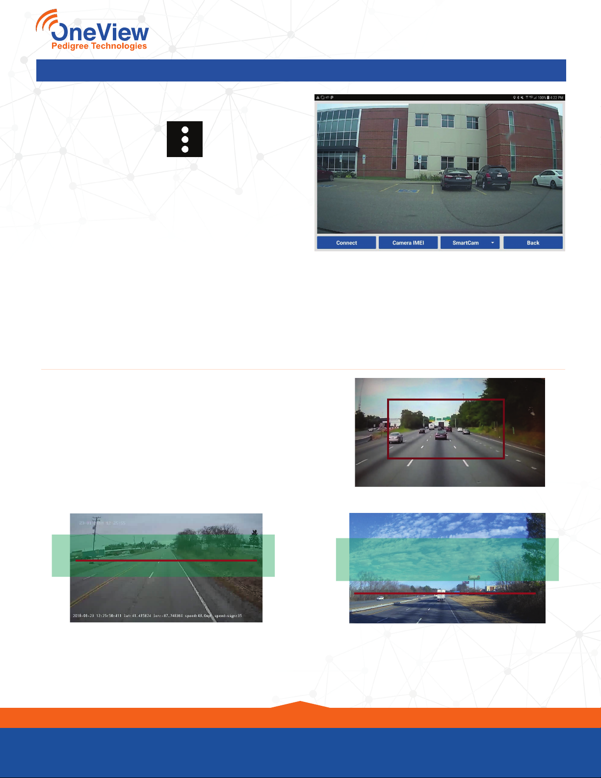
CameraView
JC400
STEP TWO
Connect the red wire 10 amp fuse to a constant power source.
It is labeled B+ and can replace your current B+ 10 amp fuse.
Test with a volt meter to make sure that power is constant. (Any
10 amp fuse with constant power can be used.)
(Optional) Power to Fuse Tap
It may be necessary to connect the power wire to a blade fuse adapter. Snip the fuse end from the
yellow and/or red wires and attach a fuse tap to
each wire. Crimp each wire in the open end of the
adapter
Yellow Wire: Remove the ACC fuse and insert it
into the fuse adapter (maximum 10 Amps)
• Plug the adapter into the open ACC fuse slot
Red Wire: Remove the B+ fuse and insert it into the fuse adapter (maximum 10 Amps)
• Plug the adapter into the open B+ fuse slot
STEP THREE
Connect the yellow wire 10 amp fuse to a switched ignition source. It is labeled ACC and can
replace your current Accessory 10 amp fuse. Test with a volt meter to make sure that power to the
circuit is off when the ignition is off and power to the circuit is on when the ignition is on. (Any 10
amp fuse with switched ignition power can be used.)
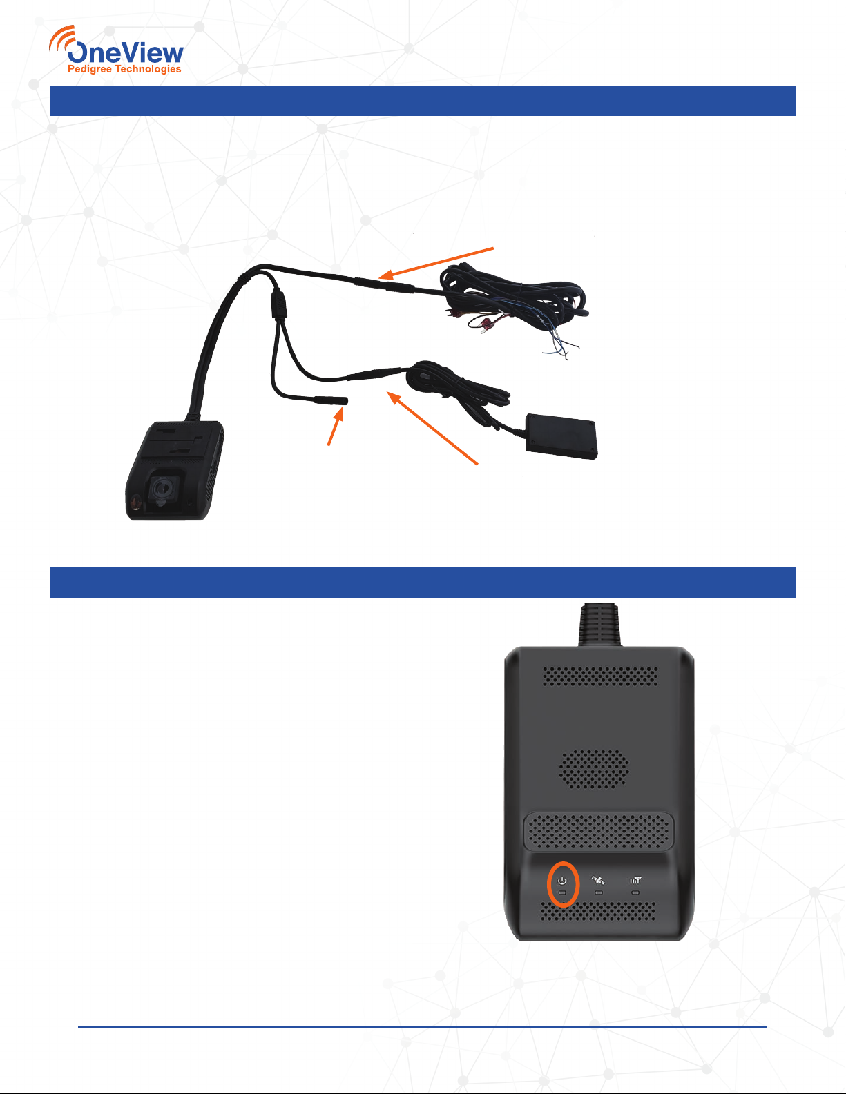
STEP ONE
Connect the ground (black) wire of the
accessory harness to DC chassis ground.
• Always connect the ground wire to an
already established ground stud when
possible.
• The frame of the vehicle is an acceptable
ground point if ground studs are not
available.
• The surface area must be clean and free of
paint, rust, or anything that will cause the
connection to fail.
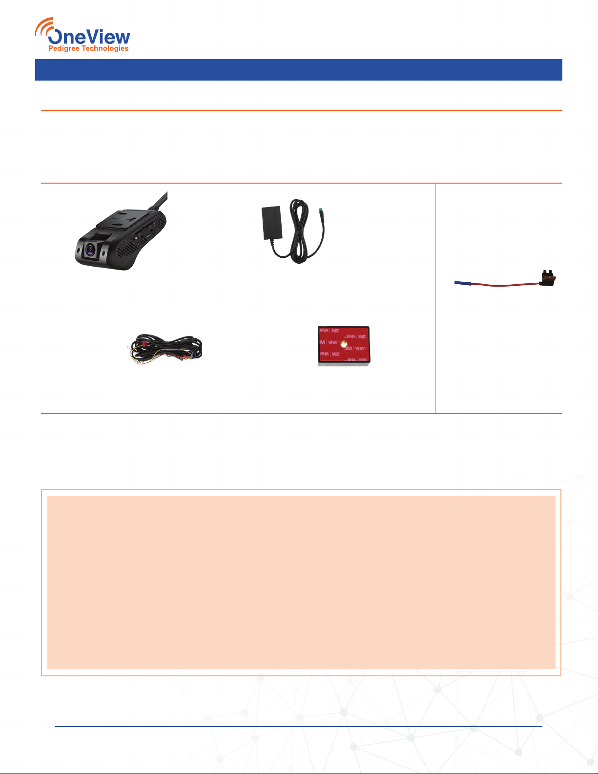
Accessory Cable
Not used
White wire not used
Note that not all ends of the accessory cable will be used for this installation (see photo above).