PEGAS 200 AC-DC User manual

PEGAS 200 AC-DC SERVISNÍ MANUÁL SERVICE MANUAL-4
page 1
ALFA IN a. s. © 2011 SERVISNÍ TECHNICKÁ DOKUMENTACE
SERVISNÍ MANUÁL PEGAS 200 AC-
DC
SERVICE MANUAL PEGAS 200 AC-
DC
1. VAROVÁNÍ WARNING
UPOZORNĚNÍ – Pouze osoba splňující
kvalifikaci danou zákonem je oprávněna
opravovat stroj.
PŘED OTEVŘENÍM KRYTU STROJE JEJ
ODPOJTE VYTAŽENÍM SÍŤOVÉ VIDLICE ZE
SÍTĚ.
Každé 4 měsíce otevřete stroj a jemněho
vyfoukejte stlačeným suchým vzduchem
POZOR, NEPOUŽÍVEJTE STLAČENÝ
VZDUCH O PŘÍLIŠ VYSOKÉM TLAKU, ABY
NEDOŠLO K MECHANICKÉMU POŠKOZENÍ
ELEKTROSOUČÁSTEK.
Každé 4 měsíce zkontrolujte řádný stav
svařovacích kabelůa síťových kabelů.
Není povolena žádná modifikace
svařovacího stroje.
Pro Vaši bezpečnost je nutné posečkat se
sundáním krytu ze stroje po odpojení ze sítě
po dobu minimálně5 minut, kdy klesne
napětí na kondenzátorech na hodnotu pod
36 V.
NOTE Only trained personnel are
permitted to work inside the machine.
BEFORE OPENING THE MACHINE, CUT
OFF ITS ELECTRICAL POWER BY
REMOVING THE PLUG FROM THE MAINS
SUPPLY SOCKET.
Every six months, open the machine and
clean it inside, using compressed
dehumidified air.
CAUTION. DO NOT USE COMPRESSED
AIR AT TOO HIGH A PRESSURE. YOU
COULD DAMAGE THE ELECTRONIC
COMPONENTS.
With the same frequency, check the
welding cables and the supply cables.
No modification, of any type, may be
made to the welding machine.
For safety while maintaining the machine,
please shut off the supply power and wait
for 5 minutes, until capacity voltage
already drops to safe voltage 36V.
2. BLOKOVÉ SCHÉMA ELECTRICAL PRINCIPLE DRAWING

PEGAS 200 AC-DC SERVISNÍ MANUÁL SERVICE MANUAL-4
page 2
ALFA IN a. s. © 2011 SERVISNÍ TECHNICKÁ DOKUMENTACE

PEGAS 200 AC-DC SERVISNÍ MANUÁL SERVICE MANUAL-4
page 3
ALFA IN a. s. © 2011 SERVISNÍ TECHNICKÁ DOKUMENTACE
3. NÁHRADNÍ DÍLY SPARE PARTS
Po
s. Item No Popis Description Quanti
ty
1 8.253.020 Držák - madlo P250 Handle P250 1
2 8.301.099 Kryt horní P250 Upper Cover P250 1
3 8.068.099 Panel přední/zadní plast P250 Plastic Front/Rear Panel P250 1
4 8.307.634 Panel zadní kov P200AC-DC Metal Rear Panel For Output
P200AC-DC
1
5 7.232.022 VypínačPegas P200AC-DC Switch On/OFF Pegas P200AC-DC 1
6 7.155.001 Průchodka P250 Cable Connector P250 1
7 7.253.013 Ventil Pegas Solenoid Valve Pegas 1
8 8.122.366 Panel pro ventilátor P200AC-
DC Metal Panel For Fan P200AC-DC 1

PEGAS 200 AC-DC SERVISNÍ MANUÁL SERVICE MANUAL-4
page 4
ALFA IN a. s. © 2011 SERVISNÍ TECHNICKÁ DOKUMENTACE
9 7.720.030 Ventilátor P250 Fan P250 1
10 7.445.311 Rezistor 6ohm P200AC-DC Rezistor 6ohm P200AC-DC 2
11 7.425.631 Tranzistor IGBT Discrete1 P40 Discrete1 IGBT P40 8
12 7.231.275 Termostat PEGAS Thermo switch 2
13 7.202.029 Držák pojistek P200AC-DC Fuse Holder P200AC-DC 1
14 7.202.123 Pojistka 3A Fuse 3A 1
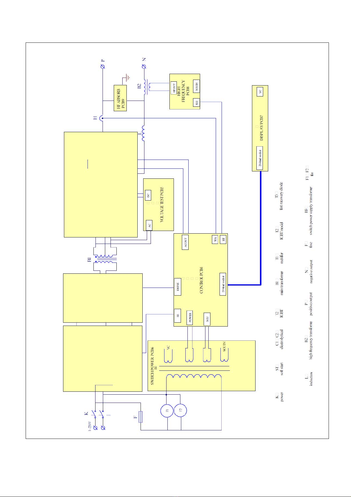
15 5.496.931 PCB EMC P200AC-DC PCB EMC P200AC-DC 1
16 5.496.526-B Spínaný zdroj PCB P200AC-DC SWITCH POWER PCB P200AC-DC 1
17 5.496.875-E PCB měření napětí Voltage test PCB P200AC-DC 1
18 5.496.626-B PCB řídící P200AC-DC Control PCB P200AC-DC 1
19 8.062.543 PCB Installation Panel P200AC-
DC
PCB Installation Panel P200AC-
DC 1
20 5.496.373-C PCB HF P200AC-DC PCB HF P200AC-DC 1
21 7.411.010 UsměrňovačPEGAS 160 E Rectifier Bridge 2
22 5.496.527-B Vstupní usměrňovačPCB
P200AC-DC Input rectifier PCB P200AC-DC 1
23 7.425.631 Tranzistor IGBT Discrete1 P40 Discrete1 IGBT P40 4
24 8.052.500 Krycí deska 2 P200AC-DC Blanking plate 2 P200AC-DC 1
25 8.050.099 Kryt boční P250 Side Cover P250 1
26 8.068.099 Panel přední/zadní plast P250 Plastic Front/Rear Panel P250 1
27 5.496.679 PCB přední P200AC-DC Front PCB P200AC-DC 1
28 8.306.300 Panel přední kov P200AC-
DC+fólie
Metal Front Panel P200AC-
DC+folie 1
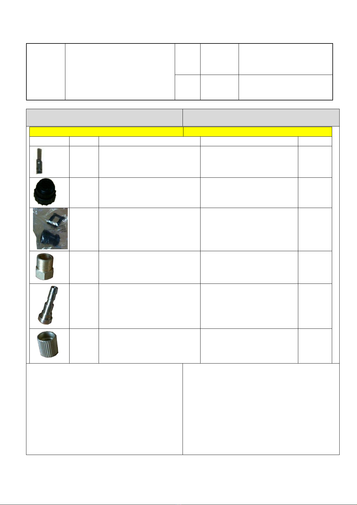
29 8.462.104 Konektor plyn Pegas P200AC-
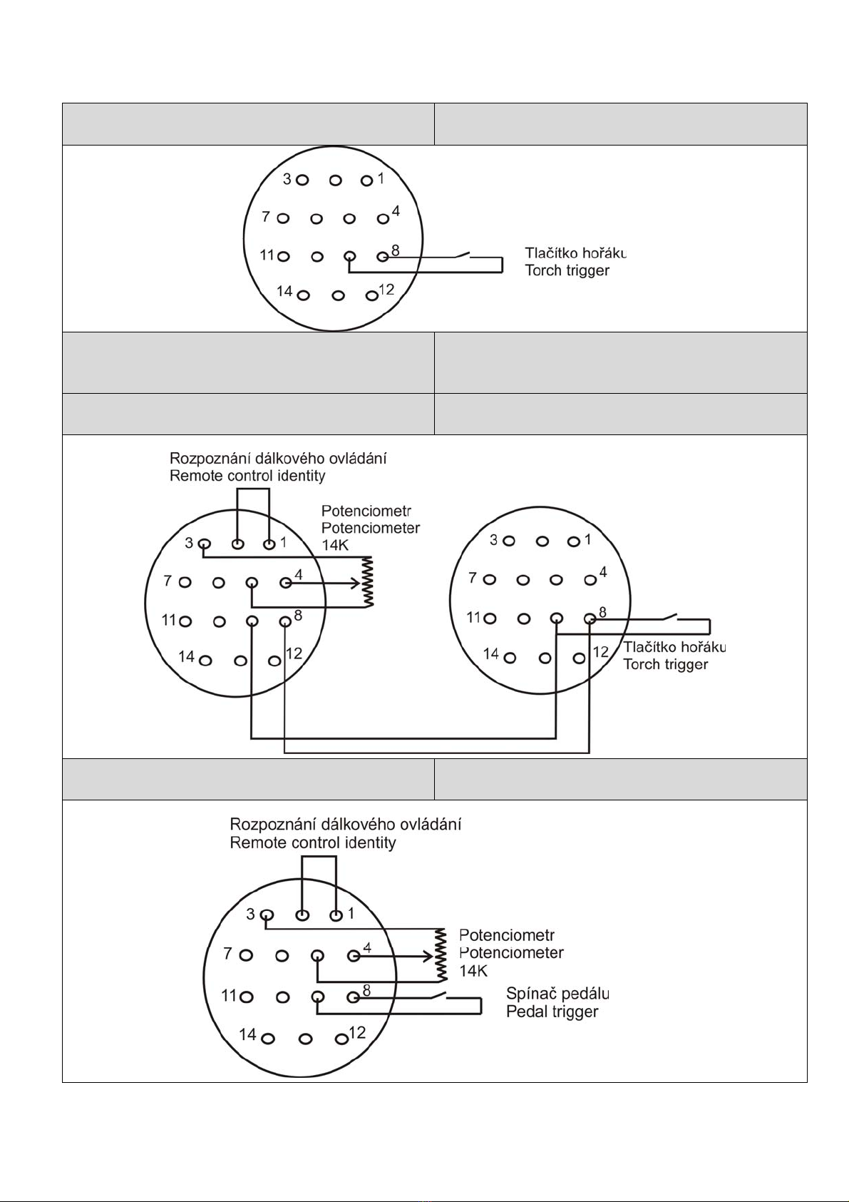
DC Gas Connector Pegas P200AC-DC 1
30 7.152.312 Rychlosp. 35-70mm P250 35-70mm Socket P250 2
31 7.132.114 Konektor zásuvka P250 14-Pin Socket P250 1
32 8.065.570 Panel přední kov spodní
P200AC-DC
Metal Front Panel For Output
P200AC-DC 1
33 6.185.515 Hlavní transformátor P200AC-
DC Main transformer P200AC-DC 1
34 8.746.029-D Box chladiče 1 P200AC-DC Heat Sink Box 1 P200AC-DC 1
35 8.425.501 Chladič1 P200AC-DC Heat Sink 1 P200AC-DC 1
36 8.425.500 Chladič2 P200AC-DC Heat Sink 2 P200AC-DC 1
37 8.052.500 Krycí deska 3 P200AC-DC Blanking plate 3 P200AC-DC 1
38 8.425.502 Chladič3 P200AC-DC Heat Sink 3 P200AC-DC 1
39 8.425.503 Chladič4 P200AC-DC Heat Sink 4 P200AC-DC 1
40 6.271.515 Tlumivka P200AC-DC Choke P200AC-DC 1
41 7.321.002 Sonda Hall 200A Pegas Hall sensor 200A Pegas 1
42 6.174.515 Trafo HF P200AC-DC Transformer HF P200AC-DC 1
43 5.496.204 HF filtr PCB P200AC-DC HF filter PCB P200AC-DC 1

PEGAS 200 AC-DC SERVISNÍ MANUÁL SERVICE MANUAL-4
page 5
ALFA IN a. s. © 2011 SERVISNÍ TECHNICKÁ DOKUMENTACE
44 8.055.543 Kryt spodní P200AC-DC Bottom Plate P200AC-DC 1
45 8.746.030 Box chladiče 2 P200AC-DC Heat Sink Box 2 P200AC-DC 1
46 5.496.674-C PCB silová P200AC-DC PCB Power P200AC-DC 1
47 7.421.681 Dioda P200AC-DC Diode P200AC-DC 2
48 8.306.301 Krycí deska 1 P200AC-DC Blanking plate 1 P200AC-DC 1
49 8.050.099 Kryt boční P250 Side Cover P250 1
50 7.735.055 Ferit odrušovací P200AC-DC Ferit Filter P200AC-DC 1
51 7.227.016 PřepínačP250 Switch P250 1
52 7.227.020 PřepínačP200AC-DC Switch P200AC-DC 2
4. TROUBLESHOOTING
S/N Troubles Reasons Solutions
1 Turn on the power source, and fan works,
but the power pilot lamp is not on.
The power light
damaged or connection
is not good
Check and repair Pr7
The transformer of
power is broken Repair or change the transformer
Control PCB failures Repair or change the control Pr4
2 Turn on the power source, and the power
pilot lamp is on, but fan doesn’t work
There is something in
the fan Clear out
The start capacitor of
fan damaged Change capacitor
The fan motor
damaged Change fan
3 Turn on the power source, the power pilot
lamp is not on, and fan doesn’t work
No power supply input Check whether there is power
supply
The fuse inside the
machine damaged Change it (3A)
4 The number on the display is not intact. The LED in the display
is broken Change the LED
5 The max and min value displayed doesn’t
accord with the set value.
The max value is not
accordant (refer to
§3.1)
Adjust potentiometer Imin on the
power board.
The min value is not
accordant (refer to
§3.1)
Adjust potentiometer Imaxin the
current meter.
6 No no-load voltage output (MMA) The machine is
damaged Check the main circuit and the Pr4.
7
Arc can
not be
ignited
(TIG)
There is spark on the HF
igniting board.
The welding cable is
not connected with the
two output of the
welder.
Connect the welding cable to the
welder’s output.
The welding cable
damaged. Repair or change it.
The earth cable
connected unstably. Check the earth cable.
The welding cable is
too long. Use an appropriate welding cable.
There is oil or dust on
the workpiece. Check and remove it.

PEGAS 200 AC-DC SERVISNÍ MANUÁL SERVICE MANUAL-4
page 6
ALFA IN a. s. © 2011 SERVISNÍ TECHNICKÁ DOKUMENTACE
The distance between
tungsten electrode
and workpiece is too
long.
Reduce the distance (about 3mm).
There is not spark on the HF
igniting board.
The HF igniting board
does not work. Repair or change Pr8
The distance between
the discharger is too
short.
Adjust this distance (about 0.7mm).
The malfunction of the
welding gun switch.
Check the welding gun switch,
control cable and aero socket.
8 No gas flow (TIG)
Gas cylinder is close or
gas pressure is low Open or change the gas cylinder
Something in the valve Remove it
Electromagnetic valve
is damaged Change it
9
Gas always flows
The gas-test on the
front panel is on The gas-test on the front panel is off
Something in the valve Remove it
Electromagnetic valve
is damaged Change it
The adjustment knob of
pre-gas time on the
front panel is damaged
Repair or change it
10 The welding current can not be adjusted
The welding current
potentiometer on the
front panel connection
is not good or damaged
Repair or change the potentiometer
11 No AC output while selecting “AC”
The power PCB is in
trouble. Repair or change it.
The AC drive PCB
damaged. Change it.
The AC IGBT module
damaged. Change it.
12 The welding current displayed isn’t
accordant with the actual value.
The min value
displayed isn’t
accordant with the
actual value. (Please
refer to §3.1)
Adjust potentiometer Imin on the
power board.
The max value
displayed isn’t
accordant with the
actual value. (Please
refer to §3.1)
Adjust potentiometer Imax on the
power board.
13 The penetration of molten pool is not
enough.
The welding current is
adjusted too low Increase the welding current
The arc is too long in
the welding process Use 2T operation
14 The alarm light on the front panel is on
Over
heat
protecti
on
Two much
welding
current
Reduce the welding current output
Working time
too long
Reduce the duty cycle (work
intermittently)
Over-
voltage
protecti
on
Power
supply
fluctuates
Using the stable power supply
Low-
voltage
protecti
Power
supply
fluctuates
Using the stable power supply

PEGAS 200 AC-DC SERVISNÍ MANUÁL SERVICE MANUAL-4
page 7
ALFA IN a. s. © 2011 SERVISNÍ TECHNICKÁ DOKUMENTACE
on Too many
machines
using power
supply in the
same time
Reduce the machines using power
supply in the same time
Over-
current
protecti
on
Unusual
current in the
main circuit
Check and repair the main circuit
and drive Pr6
5. Konektor Connector
5.0189SadakonektorůproPEGASAC/DCAERO5.0189SetofConnectorsforPEGASAC/DCAERO
ImageKódCZENQuantity
5.0181PINprokonektorPEGASDOVMaleAEROplugMalePIN2
5.0179KonektorPEGASAEROčeloAEROPlugPEGASpart11
5.0180KonektorPEGASAEROkrytAEROplugPEGASpart21
5.0182PřipojeníplynuPEGASAC/DC
maticepřevlečná
Gasfittingpart1PEGASAC/DC 1
5.0183PřipojeníplynuPEGASAC/DC
koncovka
Gasfittingpart2PEGASAC/DC 1
5.0184PřipojeníplynuPEGASAC/DCmatice
zajišťovací
Gasfittingpart3PEGASAC/DC 1
Sada 5.0198 obsahuje pouze dva piny. Pro
zapojení různých druhůdálkového ovládání
budete potřebovat více pinů. Viz schémata
níže.
The set 5.0198 content two pieces of PINs. In
order to connect different kinds of remote
controls you will need order more PINs. See
the schemas below.

PEGAS 200 AC-DC SERVISNÍ MANUÁL SERVICE MANUAL-4
page 8
ALFA IN a. s. © 2011 SERVISNÍ TECHNICKÁ DOKUMENTACE
6. Hořák Torch
7. Hořák s potenciometrem – NESMÍ SE
POUŽÍVAT
Torch with potentiometer – MAY NOT BE
USED
8. Dálkové ovládání + hořák Remote Control + torch
9. Nožní dálkové ovládání-pedál Remote foot control

PEGAS 200 AC-DC SERVISNÍ MANUÁL SERVICE MANUAL-4
page 9
ALFA IN a. s. © 2011 SERVISNÍ TECHNICKÁ DOKUMENTACE
5. Zapojení plynového konektoru Gas connector
1. Na plynovou hadici nasaďte dílec C
2. Sešroubujte dílec A a B
3. Nasaďte trn z dílce A do hadice
4. Pevněutáhněte dílec B, tak, že vznikne
mezera mezi osazením dílce A a dílcem
B. Tím se zajistí hadice (viz obr. Níže).
1. Fit C onto the hose
2. Screw A and B together
3. Fit the nipple of A into the hose
4. Firmly tighten B in the way that between
A and B appears a gap. That way you
fix the hose (see the image below)
Worked out: DJ 22/9/2011 Revised: VH 9/7/201 Approved: VH 9/7/201
Table of contents