PEHA 960/3 PSB/JR User manual

Paul Hochköpper GmbH & Co. KG
Postfach 1727 • D-58467 Lüdenscheid • Tel.: +49 (0)2351 185-0 • Fax: +49 (0)2351 27666 • e-mail: [email protected] • Internet: www.peha.de
D - 1126250-03960-3 PSB-JR (Rev04_090423) D - 1
Installations- und Bedienungsanleitung
PHC-Systembox Rollladen/Jalousie
Art.Nr.: 960/3 PSB/JR
D
1. Allgemeines
1.1 Verwendung
Die Jalousie-/Rollladenbox (JR-Box) hat 8 Eingänge (Input 8-15), die mit
Tastern gegen Masse (0V) geschaltet werden. Damit erfolgt die Ansteue-
rung der Ausgänge von PHC-Ausgangsmodulen oder PHC-Systemboxen.
Die 4 Ausgänge (Out 0-3) der JR-Box dienen zum Anschluß von jeweils
einer Jalousie oder Rolllade. Sie werden über eine 3-polige Durchgangs-
verdrahtung mit einer Spannung von 230 V~/50-60 Hz versorgt.
1.2 Garantiebestimmungen
Diese Bedienungsanleitung ist Bestandteil des Gerätes und der Garantie-
bedingungen. Sie ist dem Benutzer zu überreichen. Die technische Bauart
der Geräte kann sich ohne vorherige Ankündigung ändern. PEHA Pro-
dukte sind mit modernsten Technologien nach geltenden nationalen und
internationalen Vorschriften hergestellt und qualitätsgeprüft. Sollte sich
dennoch ein Mangel zeigen, übernimmt PEHA, unbeschadet der Ansprü-
che des Endverbrauchers aus dem Kaufvertrag gegenüber seinem Händ-
ler, die Mängelbeseitigung wie folgt:
Im Falle eines berechtigten und ordnungsgemäß geltend gemachten An-
spruchs wird PEHA nach eigener Wahl den Mangel des Gerätes beseitigen
oder ein mangelfreies Gerät liefern. Weitergehende Ansprüche und Er-
satz von Folgeschäden sind ausgeschlossen. Ein berechtigter Mangel liegt
dann vor, wenn das Gerät bei Übergabe an den Endverbraucher durch
einen Konstruktions-, Fertigungs- oder Materialfehler unbrauchbar oder
in seiner Brauchbarkeit erheblich beeinträchtigt ist. Die Gewährleistung
entfällt bei natürlichem Verschleiß, unsachgemäßer Verwendung, Falsch-
anschluss, Eingriff ins Gerät oder äußerer Einwirkung.
Die Anspruchsfrist beträgt 24 Monate ab Kauf des Gerätes durch den End-
verbraucher bei einem Händler und endet spätestens 36 Monate nach
Herstellung des Gerätes. Für die Abwicklung von Gewährleistungsansprü-
chen gilt Deutsches Recht.
1.3 Entsorgung des Gerätes
Zur Entsorgung des Gerätes sind die geltenden Gesetze und Normen des
Landes einzuhalten, in dem das Gerät betrieben wird!
2. Sicherheit
VORSICHT! Gefahr eines Stromschlages! Im Inneren des
Gehäuses befinden sich spannungsführende Teile. Eine Be-
rührung kann eine Körperverletzung zur Folge haben! Alle
Arbeiten am Versorgungsnetz und Gerät dürfen nur von
autorisierten Elektrofachkräften durchgeführt werden.
•VorallenArbeiten Gerät spannungsfrei schalten.
•GerätgegenWiedereinschaltensichern.
•GerätaufSpannungsfreiheitüberprüfen.
•VordemEinschaltenGehäusefestverschließen.
Folgende Punkte sind zu berücksichtigen:
•DiegeltendenGesetze,NormenundVorschriften.
•DerStandderTechnikzumZeitpunktderInstallation.
•DasPHC-HandbuchunddieBedienungsanleitungenderPHC-Module.
•EineBedienungsanleitungkannnurallgemeineBestimmungenanführen.
Diese sind im Zusammenhang mit einer spezifischen Anlage zu sehen.
Folgende Anlagen dürfen nicht geschaltet werden:
•SicherheitsschaltungenwieNOT-AUS
•Notstromversorgungen
•Feueralarmanlagen
•Notbeleuchtungsanlagen
Das Gerät ist nur für die bestimmungsgemäße Verwendung vorgesehen.
EineigenmächtigerUmbauodereineVeränderungistverboten!Esdarf
nicht in Verbindung mit anderen Geräten verwendet werden, durch deren
Betrieb Gefahren für Menschen, Tiere oder Sachwerte entstehen können.
3. Technische Daten
Hinweis: Zur Berechnung des Stromverbrauches für die Stromversor-
gung sollte ein Verbrauch von 60 mA vorgesehen werden. Beim Einschal-
ten der Relais erhöht sich der Strom für ca. 1 s auf 150 mA!
4. Montage und Installation
4.1 Sicherheitshinweis
Die Montage, Installation und Inbetriebnahme darf nur von autorisierten
Elektrofachkräften durchgeführt werden. Bei der Installation an das Ver-
sorgungsnetz (230 V~/50 Hz) ist die elektrische Anlage spannungsfrei zu
schalten. Es sind die geltenden Gesetze und Normen des Landes einzuhal-
ten, in dem das Gerät betrieben wird.
4.2 Montage
Die JR-Box kann dezentral mit den mitgelieferten Schrauben und Dübeln
montiert werden (z.B. auf eine ebene Wand oder in eine Zwischendecke).
DasUnterteilderJR-BoxwirdalsSchablonefürdieBohrlöcherbenutzt.
4.3 Kodierschalter
Mit dem Kodierschalter wird die Moduladresse eingestellt. Die Einstellung
ist in der PHC-Software unter dem Menüpunkt „Komponenten Module“
dargestellt (s. auch Punkt 6.1).
Hinweise:
– Nicht gleiche Moduladressen für JR-Boxen einstellen.
– Vor Einstellung der Moduladresse Spannungsversorgung ausschalten
unddaraufachten,dasskeineelektrischeEntladungstattndet.
4.4 Anschluss Datenverbindung
Die DatenverbindungfürdieJR-Boxerfolgtam„BUS-IN“-Eingang.EineDa-
tenverbindung für weitere PHC-Systemboxen oder PHC-Module erfolgt am
„BUS-OUT“-Ausgang.ÜblicherweisewirdalsDatenleitungeineJY(ST)YLei-
tung von 2x 2x 0,8 mm Ø verwendet. Sie wird an die mitgelieferten 4-po-
ligen Verbindungsklemmen angeschlossen.
Hinweise:
– Vor Anschluss oder Trennung der Busleitung Spannungs-
versorgung ausschalten.
– Die Position des Moduls in der Datenleitung ist beliebig.
– Über die Busleitung wird das Modul mit Spannung versorgt.
Hinweise:
– Detaillierte Fachkenntnisse zur Programmierung eines
PHC-Systems werden vorausgesetzt.
– Die PHC-Funktionen müssen für das PHC-System mit der
PHC-Software programmiert werden (s. PHC-Handbuch).
– Vor Inbetriebnahme Bedienungsanleitung sorgfältig durchlesen.
Hohlwand-Installationsklei
nverteiler
Hörgeschädigtensysmbol Hubschrauber-Landeplatz
, Warnung vor
Rotorblättern
Hunde tragen während
Rolltreppenbenutzung
Hupen Hupen geboten
-2.Vorschlag-
Hygienischen Atemschutz
benutzen
Im Brandfall keinen
Aufzug benutzen!
Im Brandfall werden sie
alarmiert! W enn Sie einen
Brand entdecken, Brand
Impulslichtbogenschweiß
en
Imputz-Installationsdose Inert-Gas-Einrichrung
Infektiöse Stoffe
[Unterklasse 6.2] [IMO]
Information für die
Feuerwehr
Information,
Informationsstelle
Informieren Sie sich bitte
über die Lage der
Treppen, Notausgänge.
Inline-Skating nicht
gestattet
Installationskanal
Instrumente Instrumentiertis che,
-flächen
Internationaler
Landanschluss
Ionisierende
Strahlungsenergie
Isolierende
Schutzhandschuhe für
Arbeiten unter
Kalibriert
Kaltlicht; Elektromedizin,
Beleuchtung über
Lichtleiter
Karzinogenität
(Gefahrenkategorien 1A,
1B und 2)
Keimzell-Mutagenität
(Gefahrenkategorien 1A,
1B und 2)
Kein Handhaken
verwenden
Kein Trinkwasser Kein Trinkwasser (ISO)
Allgemeine Daten
Spannungsversorgung 230 V~/50-60 Hz (L, N, PE)
Maximallast
der Systembox 4000 W (250 VAC /16 A)
Eigenverbrauch 10-60 mA
Lebensdauer Relais ca. 40.000 Schaltungen mit max. Last
Absicherung der
Versorgungsleitung Sicherungsautomat (max. 16 A)
Kodierung 8 pol. Dipschalter für die Moduladresse
Umgebungstemperatur 0 bis + 50 °C
Lagertemperatur – 40 bis + 85 °C
Anschlüsse
8 EingängefürTaster(INPUT8-15)
davon max. 3 Schalter
1 EingangPHC-Bus(BUS-IN)
4 Ausgänge(OUT0-3)
2 AusgängePHC-Bus(BUS-OUT)
Prüfvorschriften EN 60669-2-1
Kennzeichnung CE;KEMA/KEUR
Schutzart IP20
Abmessungen L 180 mm x B 205 mm x H 48 mm
Lastdaten je Ausgang (Out 0-3)
Induktiv (Motore) 1000 VA (4 A)

Paul Hochköpper GmbH & Co. KG
Postfach 1727 • D-58467 Lüdenscheid • Tel.: +49 (0)2351 185-0 • Fax: +49 (0)2351 27666 • e-mail: [email protected] • Internet: www.peha.de
D - 2126250-03960-3 PSB-JR (Rev04_090423) D - 2
4.5 Installation
1INPUT 250V~ Eingang Spannungsversorgung 230 VAC /16 A (L, N, PE) GST 18i3 F B2 Z kieselgrau 92.933.0153.0
2OUTPUT 250V~ Ausgang zur Spannungsversorgung 230 VAC /16 A weiterer PHC-Systemboxen GST 18i3 F S2 Z kieselgrau 92.934.0153.0
3Out 0-3 Ausgang zum Anschluss einer Jalousie oder Rolllade mit max. 1000 W
Achtung! Maximallast der PHC-Systembox beachten! GST 18i4 F S2 Z schwarz 92.944.0053.1
4INPUT 8-15 Eingang für Taster, Schalter (max. 3 Schalter je PHC-Systembox) Typ 8213 BFK 8pol. 25.820.3853.0
5BUS-IN PHC-Buseingang für PHC-Bus Typ 8213 BFK 4pol. 25.840.3453.0
6BUS-OUT PHC-Busausgang für weiteres PHC-Modul Typ8213SUFK4pol.25.857.3453.0
WIELAND Serie gesis Serie wiecon
Art. Nr.: 940/24 EM RÜ DIAG
16A / 250V~
Adress switch
Address switch
3
INPUT
max. 16A / 250V~
OUTPUT
max. 16A / 250V~
INPUT 8-11
8 9 10 11 BA
+24V
BUS - IN
AB
+24V
BUS - OUT
AB
+24V
BUS - OUT
INPUT 12-15
12 13 14 15
INPUT250V~
L
N
3
µ
out 1
N
µ
µ
out 0
N
µ
OUTPUT250V~
N
L
3
µ
out 2
N
µ
µ
out 3
N
µ
16A / 250V~
ID:
Max. output per chanel 250V~
M1000VA
System-Box
Art.-Nr.: 960/3 PSB/JR
1234578
6
out 0
L
N
out 1
L
N
out 2
L
N
µ
µ
µ
16A / 250V~
Address switch
3
out 4
N
L
out 3
N
L
OUTPUT250V~
N
L
out 5
N
L
µ
µ
µ
3
INPUT250V~
L
N
3
INPUT
max. 16A / 250V~
OUTPUT
max. 16A / 250V~
INPUT 8-11
8 9 10 11 BA
+24V
BUS - IN
AB
+24V
BUS - OUT
AB
+24V
BUS - OUT
INPUT 12-15
12 13 14 15
ID:
M
2300W
600VA
1250W
2AX
Max. output per chanel 250V~
Art.-Nr.: 960/3 PSB
System-Box
1234578
6
Art. Nr.: 940/24 EM RÜ DIAG
16A / 250V~
Adress switch
Address switch
3
INPUT
max. 16A / 250V~
OUTPUT
max. 16A / 250V~
INPUT 8-11
8 9 10 11 BA
+24V
BUS - IN
AB
+24V
BUS - OUT
AB
+24V
BUS - OUT
INPUT 12-15
12 13 14 15
INPUT250V~
L
N
3
µ
out 1
N
µ
µ
out 0
N
µ
OUTPUT250V~
N
L
3
µ
out 2
N
µ
µ
out 3
N
µ
16A / 250V~
ID:
Max. output per chanel 250V~
M1000VA
System-Box
Art.-Nr.: 960/3 PSB/JR
1234578
6
Kodierschalter (Moduladresse)
12
4 45 6 6
Anschlussbild Jalousie-/Rollladenbox
z.B. Anschluss von
Taster an Input 8
┴B A 24 24 A B ┴24 A B ┴
3
3
3
3
Achtung! Nur die zugelassenen Steckverbinder von Wieland verwenden! Die Steckverbinder so tief in den vorgesehenen Anschluss ein-
stecken, dass sie deutlich hörbar einrasten!
Die Steckverbinder können bei PEHA oder WIELAND
(www.wieland.de)
nach
bestellt werden.
Achtung! Die Maximallast der PHC-Systembox (max. 4000 W / 250 VAC /16A) ist beim Anschluss der Verbraucher zu beachten!
Achtung! Die Tastereingänge sind mit der Versorgungsspannung des PHC-Systems verbunden. Es ist darauf zu achten, dass keine Verbindung
zu Wechselstromkreisen (230 VAC) hergestellt wird. Eine solcher Anschluss kann zum Defekt des PHC-Systems führen!
Achtung! Beim Anschluss der Datenleitung ist darauf zu achten, dass die Anschlussbelegung nicht vertauscht wird!
Achtung! UmdenvollenFunktionsumfangderPHC-Systemboxzugewährleistenmussdie230VACVersorgungsspannungangeschlossensein!
Klemmvorrichtung mit Schrau-
bendreher herunterdrücken!

Paul Hochköpper GmbH & Co. KG
Postfach 1727 • D-58467 Lüdenscheid • Tel.: +49 (0)2351 185-0 • Fax: +49 (0)2351 27666 • e-mail: [email protected] • Internet: www.peha.de
D - 3126250-03960-3 PSB-JR (Rev04_090423) D - 3
5. Inbetriebnahme
•InstallationvornehmenundElektrischeAnlageeinschalten.
•ProgrammierungderPHC-FunktionenmitderPHC-Softwarevornehmen.
•ProgrammübertragungmitderPHC-Softwarevornehmen.
6. PHC Software
Die Programmierung der Ein- u. Ausgangsfunktionen der JR-Box muss in
der PHC-Software vorgenommen werden (s. PHC-Handbuch).
Hinweis:
In der PHC-Software verfügt die Jalousie-/Rollladenbox über vier separate
Zeitmessausgänge. Ein Zeitmessausgang wird z.B in den Rollladen-/Ja-
lousiengruppen zur Zeitmessung der Sonnenverzögerung verwendet.
6.1 Modul anlegen und Moduladresse
Das Anlegen der JR-Box erfolgt unter
„Einbaumodule Einbaubox Rolllade“:
Die Einstellung der Moduladresse erfolgt unter „Komponenten Module“:
6.2 Einschaltbedingungen
InderPHC-SoftwarekönnendieSchaltzuständederAusgänge(AUS,Me-
mory und EIN) bei Spannungseinschaltung oder Spannungswiederkehr
eingestellt werden.
Die Einstellung der Einschaltbedingungen erfolgt unter
„Komponenten
Einschaltbedingungen
“:
Die
Einschaltbedingungen
sindauf„AUS“voreingestellt.DieSchaltungs-
bedingung „Memory“ wird z.B. ausgewählt, wenn die JR-box nach einer
Spannungsunterbrechung (> 50ms) ihren vorherigen Schaltungszustand
von der Steuerung erhalten soll.
7. Störungsdiagnose-/behebung (Elektrofachkraft)
7.1 Neuanlage oder vorhandene Anlage
•SicherungsautomatundSpannungsversorgungprüfen.
•Angeschlossenen Verbraucher und Anschlussleitungen prüfen.
•Moduladresse(Kodierschalter)überprüfen.
•PHC-Programmierung überprüfen und neu übertragen
(s. PHC-Handbuch).
7.2 Kontakt
Telefon: ..................... +49 (0)2351 185-0
Telefax:...................... +49(0)235127666
Internet: ....................www.peha.de/contact.aspx
E-Mail:....................... [email protected]

Paul Hochköpper GmbH & Co. KG
Postfach 1727 • D-58467 Lüdenscheid • Tel.: +49 (0)2351 185-0 • Fax: +49 (0)2351 27666 • e-mail: [email protected] • Internet: www.peha.de
D - 1126250-03960-3 PSB-JR (Rev04_090423) GB - 1
Notes:
– Detailed expert knowledge for programming a PHC system
are required.
– The PHC-functions for the PHC system are to be programmed
with the PHC system software (see PHC manual).
– Read through the operating instructions carefully before putting
the device into service.
Hohlwand-Installationsklei
nverteiler
Hörgeschädigtensysmbol Hubschrauber-Landeplatz
, Warnung vor
Rotorblättern
Hunde tragen während
Rolltreppenbenutzung
Hupen Hupen geboten
-2.Vorschlag-
Hygienischen Atemschutz
benutzen
Im Brandfall keinen
Aufzug benutzen!
Im Brandfall werden sie
alarmiert! W enn Sie einen
Brand entdecken, Brand
Impulslichtbogenschweiß
en
Imputz-Installationsdose Inert-Gas-Einrichrung
Infektiöse Stoffe
[Unterklasse 6.2] [IMO]
Information für die
Feuerwehr
Information,
Informationsstelle
Informieren Sie sich bitte
über die Lage der
Treppen, Notausgänge.
Inline-Skating nicht
gestattet
Installationskanal
Instrumente Instrumentiertis che,
-flächen
Internationaler
Landanschluss
Ionisierende
Strahlungsenergie
Isolierende
Schutzhandschuhe für
Arbeiten unter
Kalibriert
Kaltlicht; Elektromedizin,
Beleuchtung über
Lichtleiter
Karzinogenität
(Gefahrenkategorien 1A,
1B und 2)
Keimzell-Mutagenität
(Gefahrenkategorien 1A,
1B und 2)
Kein Handhaken
verwenden
Kein Trinkwasser Kein Trinkwasser (ISO)
Installation and operating instructions
PHC blind/shutter system box
Art.no.: 960/3 PSB/JR
GB
1. General
1.1 Application
The PHC blind/shutter box (BS-box) has 8 inputs (Input 8-15) that can be
switched against ground (0V) using push buttons. The inputs can be used to
control the outputs of the PHC output modules or of the PHC system boxes.
The 4 outputs (Out 0-3) of the
BS-box
are used to activate in each case a
blind or shutter. They are supplied by a 3 pole through line carrying with
a voltage of 230 V~/50-60 Hz.
1.2 Warranty conditions
These operating instructions are an integral part of both the device and
our terms of warranty. They must be handed over to the user. The tech-
nical design of the appliance is subject to change without prior notifi-
cation. PEHA products are manufactured and quality-checked with the
latest technology according to applicable national and international regu-
lations. Nevertheless, if a product should exhibit a defect, PEHA warrants
to make remedy as follows (regardless of any claims against the dealer to
which the end-user may be entitled as a result of the sales transaction):
In the event of a justified and properly-established claim, PEHA shall ex-
ercise its prerogative to either repair or replace the defective device. Fur-
ther claims or liability for consequential damage are explicitly excluded. A
justifiable deficiency is one in which the device exhibits a structural, ma-
nufacturing, or material defect that makes it unusable or substantially im-
pairs its utility at the time it is turned over to the end-user. The warranty
does not apply to natural wear, unintended usage, incorrect connection,
device tampering or the effects of external influences.
The warranty period is for 24 months from the date of purchase by the
end-user from a dealer and ends not later than 36 months after the
device’s date of manufacture. German law shall be applicable for the set-
tlement of warranty claims.
1.3 Disposal of the device
The device must be disposed of in compliance with the laws and standards
of the country in which it is operated!
2. Safety
CAUTION! Danger of electrical shock!
The housing contains
current-carrying components. Contact can lead
to personal
injury! All work on the mains network and the device may
only be done by an authorised electrician.
•Disconnectpowersupplyfromthedevicepriortoperforminganyworkonit.
•Securethedeviceagainstbeingpoweredonagain.
•Checkthatthedeviceispoweredoff.
•Closethehousingsecurelybeforeapplyingpower.
The following must be observed:
•Prevailingstatutes,standardsandregulations.
•State-of-the-arttechnologyatthetimeofinstallation.
•
The PHC manual and operating instructions of the PHC modules.
•Operatinginstructionscanonlycitegeneralstipulations.Theseareto
be viewed in the context of a specific system.
The following systems may not be switched:
•
SafetyswitchessuchasEMERGENCYOFF
•
Emergency power supplies
•
Fire alarm systems
•
Emergency lighting systems
Thisdeviceisonlyintendedtobeusedforitsstatedapplication.Unautho-
rised conversions, modifications or changes are not permissible!
This device may not be used in conjunction with other devices whose ope-
ration could present a hazard to persons, animals or property.
3. Technical specifications
Note: To calculate the current consumption for the power supply, you
should assume a consumption of 60 mA. The power consumption incre-
ases to 150 mA for about 1 s when switching on the relays.
4. Mounting and Installation
4.1 Safety information
Installation and commissioning may only be done by an authorised electri-
cian. Mains power (230 VAC /50 Hz) to electrical equipment must be swit-
ched off during installation. Applicable laws and standards of the country
in which the device is operated must be observed!
4.2 Mounting
The PHC BS-box can be mounted in any location using the included screws
and plugs (e.g. onto a smooth wall or inserted ceiling ). The base of the
PHC BS-box is used as a template for the drill holes.
4.3 Coding switch
The coding switch sets the module address. The setting is
presented in
the PHC software under menu item „Components Modules“ (see also
point 6.1).
Notes:
– Do not set the same module addresses for PHC BS-boxes.
–
Before setting the module address, the PHC module needs to be
switched off and it must be secured against electrical discharge.
4.4 Data connection
Usually,aJY(ST)Y2x2x0,8mmØcableisusedasadataline.Thecable
is connected to the 4 pole connectors (included). The data connection to
thePHCBS-boxiscarriedoutatthe„BUS-IN“input.Adataconnection
forfurtherPHCsystemboxesorPHCmodulesiscarriedoutatthe„BUS-
OUT“output.
Notes:
– Switch off power supply before connecting or disconnecting bus line.
– The module can be positioned anywhere in the data line.
– The module is supplied with voltage by the bus line.
General data
Power supply 230 VAC /50-60 Hz (L, N, PE)
Maximal load of
the system box 4000 W (250 VAC / 16 A)
Own consumption 10-60 mA
Relay service life ca. 40.000 applications at max. load
Power line protection Circuit breaker (max. 16 A)
Coding 8 pole dip switch for module address
Ambient temperature 0 to + 50 °C
Storage temperature – 40 to + 85 °C
Connections
8 Push button inputs(INPUT8-15)
3 switches max. allowed!
1 PHC bus input(BUS-IN)
4 Outputs(OUT0-3)
2 PHC bus output(BUS-OUT)
Test specications EN 60669-2-1
Certifications CE;KEMA/KEUR
Protection type IP20
Dimensions L 180 mm x W 205 mm x H 48 mm
Load specifications per output (Out 0-3)
Inductive (Motor) 1000 VA (4 A)

Paul Hochköpper GmbH & Co. KG
Postfach 1727 • D-58467 Lüdenscheid • Tel.: +49 (0)2351 185-0 • Fax: +49 (0)2351 27666 • e-mail: [email protected] • Internet: www.peha.de
D - 2126250-03960-3 PSB-JR (Rev04_090423) GB - 2
4.5 Installation
1INPUT 250V~ Input for Power supply 230 VAC /16 A (L, N, PE) GST 18i3 F B2 Z charcoal 92.933.0153.0
2OUTPUT 250V~ Output for power supply 230 VAC /16A of further PHC system boxes GST 18i3 F S2 Z charcoal 92.934.0153.0
3Out 0-3 Output for connecting of a blind or shutter with max. 1000 W
Caution! The maximum load of the PHC system box must be observed! GST 18i4 F S2 Z black 92.944.0053.1
4INPUT 8-15 Input for push button, switch (max. 3 switches per PHC system boxes) Type 8213 BFK 8 pole 25.820.3853.0
5BUS-IN PHC bus input for PHC bus Type 8213 BFK 4 pole 25.840.3453.0
6BUS-OUT PHC bus output for further PHC module Type8213SUFK4pole25.857.3453.0
WIELAND gesis range wiecon range
Caution! Only use approved „Wieland“ connectors! Plug the connector into the provided connection until you hear them engage into place!
The connectors can be reordered from PEHA or WIELAND (www.wieland.de).
Caution! The maximum load of the PHC system box (max. 4000 W / 250 VAC /16A) must be observed when connecting consumers!
Caution! The inputs for push buttons are connected to the supply voltage of the PEHA PHC system. Care must be taken to ensure that no
connection is made to alternating current circuits (230 VAC). Such a connection can damage the PHC system!
Caution! During connection, care must be taken to ensure that the connector assignment of the data cable is not interchanged.
Caution! In order to guarantee the full range of functions of the PHC system box, the 230 VAC power supply must be connected!
Art. Nr.: 940/24 EM RÜ DIAG
16A / 250V~
Adress switch
Address switch
3
INPUT
max. 16A / 250V~
OUTPUT
max. 16A / 250V~
INPUT 8-11
8 9 10 11 BA
+24V
BUS - IN
AB
+24V
BUS - OUT
AB
+24V
BUS - OUT
INPUT 12-15
12 13 14 15
INPUT250V~
L
N
3
µ
out 1
N
µ
µ
out 0
N
µ
OUTPUT250V~
N
L
3
µ
out 2
N
µ
µ
out 3
N
µ
16A / 250V~
ID:
Max. output per chanel 250V~
M1000VA
System-Box
Art.-Nr.: 960/3 PSB/JR
1234578
6
out 0
L
N
out 1
L
N
out 2
L
N
µ
µ
µ
16A / 250V~
Address switch
3
out 4
N
L
out 3
N
L
OUTPUT250V~
N
L
out 5
N
L
µ
µ
µ
3
INPUT250V~
L
N
3
INPUT
max. 16A / 250V~
OUTPUT
max. 16A / 250V~
INPUT 8-11
8 9 10 11 BA
+24V
BUS - IN
AB
+24V
BUS - OUT
AB
+24V
BUS - OUT
INPUT 12-15
12 13 14 15
ID:
M
2300W
600VA
1250W
2AX
Max. output per chanel 250V~
Art.-Nr.: 960/3 PSB
System-Box
1234578
6
Art. Nr.: 940/24 EM RÜ DIAG
16A / 250V~
Adress switch
Address switch
3
INPUT
max. 16A / 250V~
OUTPUT
max. 16A / 250V~
INPUT 8-11
8 9 10 11 BA
+24V
BUS - IN
AB
+24V
BUS - OUT
AB
+24V
BUS - OUT
INPUT 12-15
12 13 14 15
INPUT250V~
L
N
3
µ
out 1
N
µ
µ
out 0
N
µ
OUTPUT250V~
N
L
3
µ
out 2
N
µ
µ
out 3
N
µ
16A / 250V~
ID:
Max. output per chanel 250V~
M1000VA
System-Box
Art.-Nr.: 960/3 PSB/JR
1234578
6
Art. Nr.: 940/24 EM RÜ DIAG
16A / 250V~
Adress switch
Address switch
3
INPUT
max. 16A / 250V~
OUTPUT
max. 16A / 250V~
INPUT 8-11
8 9 10 11 BA
+24V
BUS - IN
AB
+24V
BUS - OUT
AB
+24V
BUS - OUT
INPUT 12-15
12 13 14 15
INPUT250V~
L
N
3
µ
out 1
N
µ
µ
out 0
N
µ
OUTPUT250V~
N
L
3
µ
out 2
N
µ
µ
out 3
N
µ
16A / 250V~
ID:
Max. output per chanel 250V~
M1000VA
System-Box
Art.-Nr.: 960/3 PSB/JR
1234578
6
Code switch (modul adress)
12
4 45 6 6
Connector assignment of the
PHC blind/shutter box
e. g. push button
at input 8
┴B A 24 24 A B ┴24 A B ┴
3
3
3
3
Push down the clamping de-
vice by using a screwdriver!

Paul Hochköpper GmbH & Co. KG
Postfach 1727 • D-58467 Lüdenscheid • Tel.: +49 (0)2351 185-0 • Fax: +49 (0)2351 27666 • e-mail: [email protected] • Internet: www.peha.de
D - 3126250-03960-3 PSB-JR (Rev04_090423) GB - 3
5. Commissioning
•Carryoutinstallationandswitchonelectricalsystem(supplyline).
•
Carry out PHC programming with PHC software.
•CarryoutprogramtransferwithPHCsoftware.
6. PHC software
The input and output functions of the PHC BS-box have to be programmed
in the PHC software (see PHC manual).
Note:
In the PHC software the
PHC blind/shutter box
has four separate chrono-
metry outputs. A chronometry output is used, for example, in the blind/
shutter groups for time measuring the sun delay.
6.1 Assigning modul and modul adress
For assigning the PHC BS-box go to:
„Embedded modules embedded shutter box“
For adjusting the module address go to:
„
Components
Modules
“
6.2 Turn-on conditions
Youcanselecttheswitchingstatesoftheoutputs(OFF,MemoryandON)
on voltage switch-on or recovery in the PHC software under the menu
item „Components
Turn-on conditions“:
The turn-on conditions are pre-set to „OFF“. The „Memory“ switching con-
dition is selected, e.g. , to get the previous switching state for the BS-box
from the control module after a voltage interruption (> 50 ms).
7. Troubleshooting & remedies (electrician only)
7.1 New system or existing system
•Check circuit breaker and power supply
•Checkconnectedelectricalloadsandconnectioncables
•Check module address (coding switch).
•CheckPHCprogrammingandtransferagain.
(see PHC manual).
7.2 Contact
Telephone: .................+49 (0)2351 185-0
Fax:........................... +49(0)235127666
Internet: ....................www.peha.de/contact.aspx
E-mail: ......................[email protected]

NL - 1126250-03960-3 PSB-JR (Rev04_090423)
PEHA Elektro B.V.
Pieter Calandweg 58 • 6827 BK Arnhem • Tel.: +31 (0)26 368 7500 • Fax: +31 (0)26 368 7509 • e-mail: [email protected] • Internet: www.peha-elektro.nl
Installatie en bedieningshandleiding
PHC-systeembox rolluik / jaloezie
Art.Nr.: 960/3 PSB/JR
NL
1. Algemeen
1.1 Gebruik
De jaloezie-/rolluikbox (JR-box) heeft 8 ingangen (Input 8-15) die met
toets naar massa (0 V) kunnen worden geschakeld. Met deze ingangen
kunnen de uitgangen van PHC-uitgangsmodules of PHC-systeemboxen
worden aangestuurd.
De 4 uitgangen (Out 0-3) van de JR-box dienen voor de aansluiting van
telkens één jaloezie of rolluik.
De uitgangen worden via een 3-polige door-
gangsbedrading met een spanning van 230 V~/50-60 Hz gevoed.
1.2 Garantiebepalingen
Deze bedieningshandleiding is een onderdeel van dit apparaat en de ga-
rantiebepalingen.Udientdezeaandeeindgebruikerteoverhandigen.De
technische constructie van dit apparaat kan zich zonder voorafmelding
veranderen. PEHA producten zijn met de meest modernste technologie
en na de geldende nationale en internationale voorschriften samengesteld
en op kwaliteit gecontroleerd. Mocht u desondanks toch nog een defect
constateren dan neemt PEHA deze reclamatie via zijn verkooppunt terug
mits aan de volgende voorwaarden wordt voldaan:
In het geval van een gerechtigde en rechtvaardige gemaakte aanspraak
zal PEHA naar eigen keuze deze reclamatie vergoeden of een functione-
rend apparaat leveren. Verdere aanspraak en vergoedingen van vervolg-
schaden zijn uitgesloten. Een gerechtigde reclamatie is geldend mits het
apparaat bij overdracht aan de eindgebruiker door een constructie-, fabri-
cage-, of materiaalfout onbruikbaar of het gebruik onmogelijk maakt. De
kwaliteitsgarantie vervalt bij slijtage door natuurlijk gebruik, verkeerde
toepassing, foutief aansluiten, openen van het apparaat of andere exter-
ne invloeden. De aanspraak kan na aankoop van maximaal 24 maanden
plaats vinden en eindigt maximaal na 36 maanden na fabricage van het
apparaat. Op de afwikkeling van de garantie geldt het Duitse recht.
1.3 Toepassing van het apparaat
Voor de behandeling van het apparaat zijn de wetten en normen van het
land waar het apparaat geplaatst word van toepassing!
2. Veiligheid
OPGEPAST! Gevaar voor stroomschokken! In het binnenste
van deze behuizing bevinden zich spanningsvoerende delen.
Een aanraking hiervan kan letsel veroorzaken! Alle werk-
zaamheden aan het net en apparaten mogen alleen door
een erkend elektricien uitgevoerd worden.
•Voorallewerkzaamhedenhetapparaatspanningsloosschakelen.
•Ontvangertegenspanningsterugvalzekeren.
•Apparaatopspanningsloosheidtesten.
•Voorinschakelendebehuizingvastzetten.
De volgende punten dient men aan te houden:
•Degeldendewetten,normenenvoorschriften.
•Destandvandetechniektentijdevaninstallatie.
•HetPHC-handboekendehandleidingenvandePHC-module.
•Eenbedieningshandleidingkanalleenvooralgemenetoepassingen
gelden. Deze zijn in samenhang van een specifieke toepassing na te
zien en dienen gecontroleerd te worden.
De volgende installaties mogen niet worden geschakeld:
•
Veiligheidsschakelingen zoals NOODSTOP
•
Noodstroomverzorgingen
•
Brandalarmen
•
Noodverlichtingen
Het apparaat is alleen in deze uitvoering voorgezien. Een eigen ombouw of
verandering aan het apparaat is verboden!
Dit apparaat mag niet in com-
binatie met andere apparaten gebruikt worden waardoor enige mogelijkheid
voor gevaar voor mensen, dieren of andere toepassingen voor kan komen.
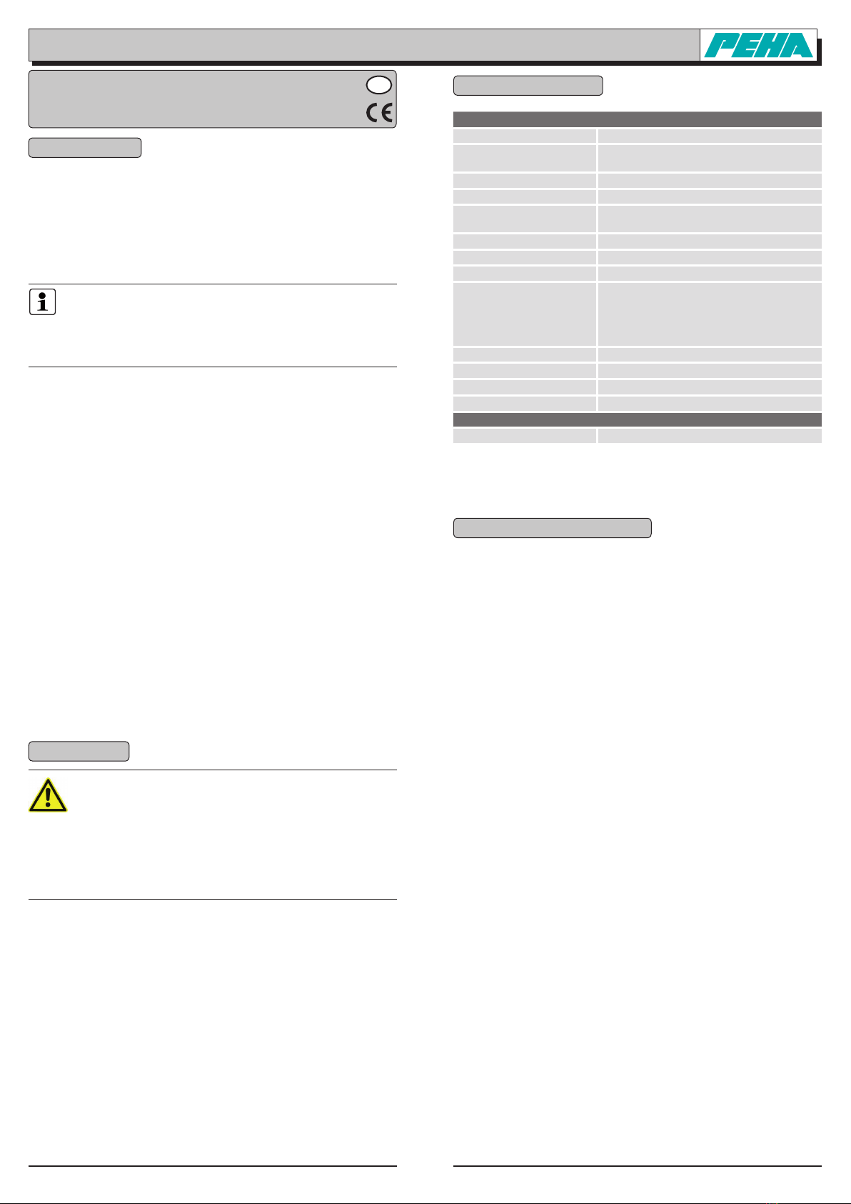
3. Technische gegevens
Opmerking: Voor de berekening van het stroomverbruik voor de stroom-
verzorging dient een verbruik van 60 mA te worden gepland. Bij het
inschakelen van de relais verhoogt de stroom voor ca. 1 sec. tot 150 mA.
4. Montage en installatie
4.1 Veiligheidsopmerkingen
De installatie en inbedrijfsname dient uitsluitend door een erkend elektri-
cien uitgevoerd worden. Bij de installatie aan het stroomverzorgingsnet
(230V/50Hz ~) dient u de installatie spanningsloos te schakelen.
Ook dient u de geldende wetten, normen en installatievoorschriften te
handhaven welke in uw land gelden.
4.2 Montage
De JR-Box kan met de bijgeleverde schroeven en pluggen decentraal wor-
den opgeschroefd (bijv. tegen een vlakke wand of in een verlaagd pla-
fond). Het onderstuk van de JR-Box wordt als sjabloon voor de te boren
gaten gebruikt.
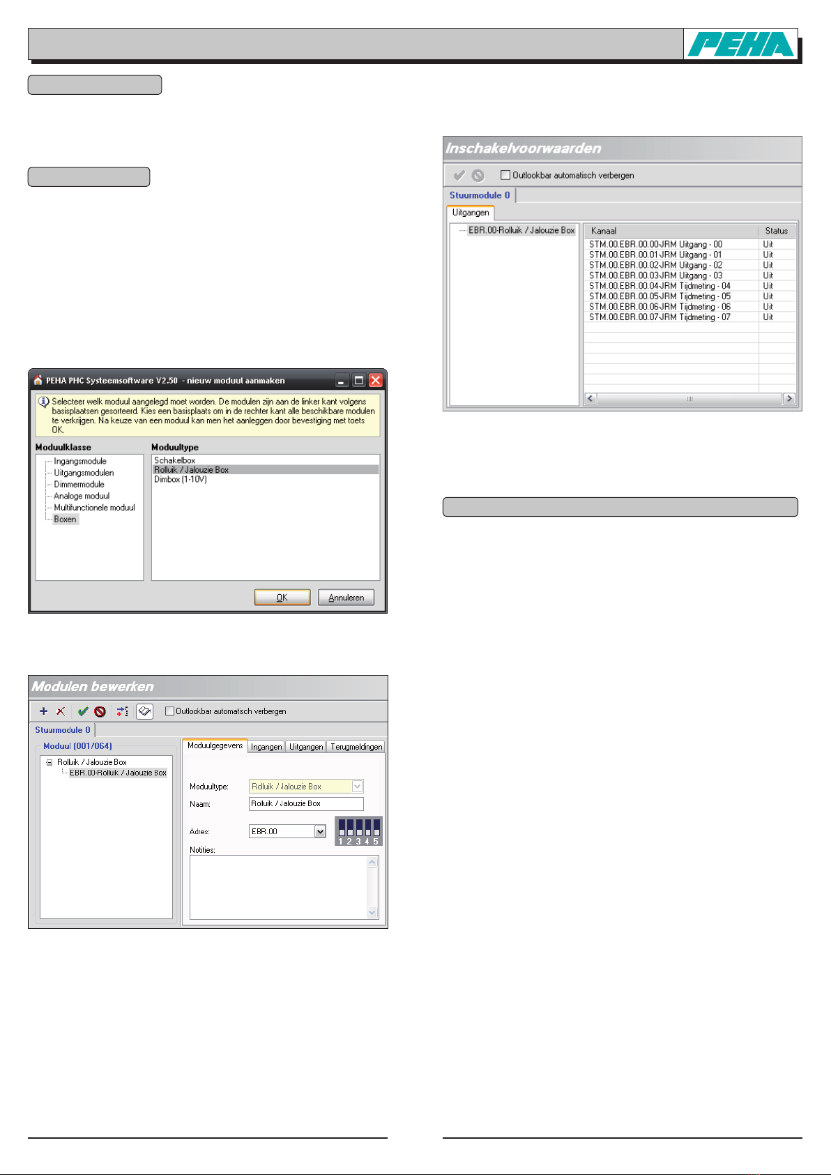
4.3 Codeerschakelaar
Met de codeerschakelaar wordt het moduleadres ingesteld. De instelling
is in de PHC-software aangegeven onder het menupunt „Componenten
Modulen“ (zie ook punt 6.1).
Opmerking:
– Stel verschillende moduleadressen voor JR-boxen in.
– Voor het moduleadres wordt ingesteld, dient de voeding te worden uit-
geschakeld. Zorg ervoor dat er geen elektrische ontlading plaatsvindt.
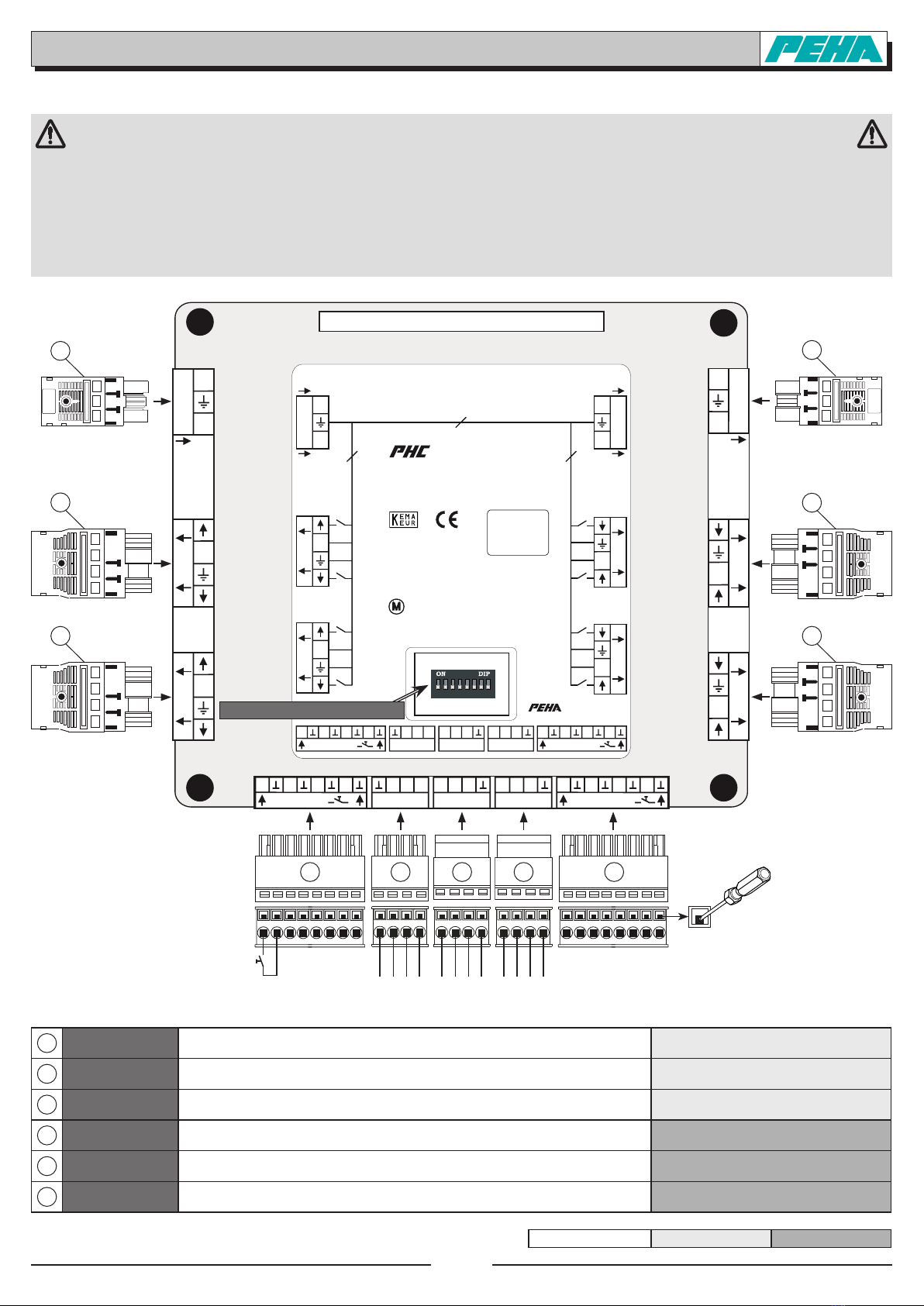
4.4 Aansluiting van de dataverbinding
De aansluiting van de dataleiding op de JR-Box gebeurt via de „BUS-
IN“-ingang. Een dataverbinding voor andere PHC-systeemboxen of PHC-
modulesgebeurtaandeBUS-OUT-uitgang..
GewoonlijkwordtalsdataleidingeenJY(ST)Y-leidingvan2x2x0,8mmØ
gebruikt. De aansluiting van de dataleiding gebeurt met een bijgeleverde
4-polige verbindingsstekker.
Opmerking:
– Vóór het loskoppelen van de busleiding dient de spanningsverzorging
te worden uitgeschakeld.
– De positie van de module in de dataleiding is willekeurig.
– Via de busleiding wordt de module van spanning voorzien.
Opmerking:
– Er wordt gedetailleerde vakkenis met betrekking tot de
programmering van een PHC-systeem verondersteld.
– De PHC-functies moeten met behulp van de PHC-software voor
het PHC-systeem worden geprogrammeerd (zie PHC-handboek).
– Voor inbedrijfsname dient u de bedieningshandleiding
zorgvuldig door te nemen.
Hohlwand-Installationsklei
nverteiler
Hörgeschädigtensysmbol Hubschrauber-Landeplatz
, Warnung vor
Rotorblättern
Hunde tragen während
Rolltreppenbenutzung
Hupen Hupen geboten
-2.Vorschlag-
Hygienischen Atemschutz
benutzen
Im Brandfall keinen
Aufzug benutzen!
Im Brandfall werden sie
alarmiert! W enn Sie einen
Brand entdecken, Brand
Impulslichtbogenschweiß
en
Imputz-Installationsdose Inert-Gas-Einrichrung
Infektiöse Stoffe
[Unterklasse 6.2] [IMO]
Information für die
Feuerwehr
Information,
Informationsstelle
Informieren Sie sich bitte
über die Lage der
Treppen, Notausgänge.
Inline-Skating nicht
gestattet
Installationskanal
Instrumente Instrumentiertis che,
-flächen
Internationaler
Landanschluss
Ionisierende
Strahlungsenergie
Isolierende
Schutzhandschuhe für
Arbeiten unter
Kalibriert
Kaltlicht; Elektromedizin,
Beleuchtung über
Lichtleiter
Karzinogenität
(Gefahrenkategorien 1A,
1B und 2)
Keimzell-Mutagenität
(Gefahrenkategorien 1A,
1B und 2)
Kein Handhaken
verwenden
Kein Trinkwasser Kein Trinkwasser (ISO)
Algemene gegevens
Bedrijfsspanning 230 V~/50-60 Hz (L, N, PE)
Maximale belasting
van de systeembox 4000 W (250 VAC / 16 A)
Eigen verbruik 10-60 mA
Levensduur relais
ca. 40.000 schakelingen met max.belasting
Beveiliging Automaat met max. 16A
Codering 8-pol. DIP-schakelaar (moduleadres)
Omgevingstemperatuur 0 tot + 50 °C
Opslagtemperatuur – 40 tot + 85 °C
Aansluitingen
8 ingangen voor toets(INPUT8-15)
max. 3 schakelaars zijn toegestaan!
1 ingang PHC-bus(BUS-IN)
4 uitgangen(OUT0-3)
2 uitgang PHC-bus(BUS-OUT)
Testvoorschriften EN 60669-2-1
Labeling CE;KEMA/KEUR
Beschermingsgraad IP20
Afmetingen 180 mm x 205 mm x 48 mm (l x b x h)
Last gegevens per uitgang (Out 0-3)
Inductief (motor) 1000 VA (4 A)

NL - 2126250-03960-3 PSB-JR (Rev04_090423)
PEHA Elektro B.V.
Pieter Calandweg 58 • 6827 BK Arnhem • Tel.: +31 (0)26 368 7500 • Fax: +31 (0)26 368 7509 • e-mail: [email protected] • Internet: www.peha-elektro.nl
4.5 Installatie
1INPUT 250V~ Ingang voor de spanningsverzorging 230 VAC /16 A (L, N, PE) GST 18i3 F B2 Z kiezelgrijs
92.933.0153.0
2OUTPUT 250V~
Uitgangvoordespanningsverzorging 230 VAC /16A van een andere PHC-systeembox
GST 18i3 F S2 Z kiezelgrijs
92.934.0153.0
3Out 0-3 Uitgangvoordeaansluitingvaneenjaloezieofrolluikmetmax.1000W
Let Op! Neem de maximale belasting van de PHC-systeembox in acht! GST 18i4 F S2 Z zwart 92.944.0053.1
4INPUT 8-15 Ingang voor toets, schakelaar (max. 3 schakelaars zijn toegestaan!) Type 8213 BFK 8-pol. 25.820.3853.0
5BUS-IN PHC-Bus ingang voor de aansluiting op de PHC-bus Type 8213 BFK 4-pol. 25.840.3453.0
6BUS-OUT PHC-Bus uitgang voor de aansluiting van een extra PHC-module Type8213SUFK4-pol.25.857.3453.0
WIELAND Serie gesis Serie wiecon
Let op! De bijgeleverde stekkers van Wieland dienen te worden gebruikt! Steek de stekkers zo diep in de betreffende aansluiting, dat ze dui-
delijk hoorbaar vastklikken! De stekkers kunnen bij PEHA of bij de firma WIELAND (www.wieland.de) worden bijbesteld.
Let op! Bij de aansluiting van de verbruikers dient rekening te worden gehouden met de maximale belasting (max. 4000 W / 250 VAC /16A)
van de PHC-systeembox!
Let op! De toets zijn met de voedingsspanning van het PEHA PHC-systeem verbonden. Men dient erop te letten dat geen verbinding met wis-
selstroomkringen (230 VAC) tot stand wordt gebracht. Een dergelijke aansluiting kan tot het defect van het PEHA PHC-systeem leiden!
Let op! Bij het aansluiten dient men erop te letten dat de aansluitdraden van de dataleiding niet worden verwisseld!
Let op! Om de volledige functionaliteit van de PHC-systeembox te garanderen, moet de 230VAC-voedingsspanning aangesloten zijn!
Art. Nr.: 940/24 EM RÜ DIAG
16A / 250V~
Adress switch
Address switch
3
INPUT
max. 16A / 250V~
OUTPUT
max. 16A / 250V~
INPUT 8-11
8 9 10 11 BA
+24V
BUS - IN
AB
+24V
BUS - OUT
AB
+24V
BUS - OUT
INPUT 12-15
12 13 14 15
INPUT250V~
L
N
3
µ
out 1
N
µ
µ
out 0
N
µ
OUTPUT250V~
N
L
3
µ
out 2
N
µ
µ
out 3
N
µ
16A / 250V~
ID:
Max. output per chanel 250V~
M1000VA
System-Box
Art.-Nr.: 960/3 PSB/JR
1234578
6
out 0
L
N
out 1
L
N
out 2
L
N
µ
µ
µ
16A / 250V~
Address switch
3
out 4
N
L
out 3
N
L
OUTPUT250V~
N
L
out 5
N
L
µ
µ
µ
3
INPUT250V~
L
N
3
INPUT
max. 16A / 250V~
OUTPUT
max. 16A / 250V~
INPUT 8-11
8 9 10 11 BA
+24V
BUS - IN
AB
+24V
BUS - OUT
AB
+24V
BUS - OUT
INPUT 12-15
12 13 14 15
ID:
M
2300W
600VA
1250W
2AX
Max. output per chanel 250V~
Art.-Nr.: 960/3 PSB
System-Box
1234578
6
Art. Nr.: 940/24 EM RÜ DIAG
16A / 250V~
Adress switch
Address switch
3
INPUT
max. 16A / 250V~
OUTPUT
max. 16A / 250V~
INPUT 8-11
8 9 10 11 BA
+24V
BUS - IN
AB
+24V
BUS - OUT
AB
+24V
BUS - OUT
INPUT 12-15
12 13 14 15
INPUT250V~
L
N
3
µ
out 1
N
µ
µ
out 0
N
µ
OUTPUT250V~
N
L
3
µ
out 2
N
µ
µ
out 3
N
µ
16A / 250V~
ID:
Max. output per chanel 250V~
M1000VA
System-Box
Art.-Nr.: 960/3 PSB/JR
1234578
6
Art. Nr.: 940/24 EM RÜ DIAG
16A / 250V~
Adress switch
Address switch
3
INPUT
max. 16A / 250V~
OUTPUT
max. 16A / 250V~
INPUT 8-11
8 9 10 11 BA
+24V
BUS - IN
AB
+24V
BUS - OUT
AB
+24V
BUS - OUT
INPUT 12-15
12 13 14 15
INPUT250V~
L
N
3
µ
out 1
N
µ
µ
out 0
N
µ
OUTPUT250V~
N
L
3
µ
out 2
N
µ
µ
out 3
N
µ
16A / 250V~
ID:
Max. output per chanel 250V~
M1000VA
System-Box
Art.-Nr.: 960/3 PSB/JR
1234578
6
Codeerschakelaar (moduleadres)
12
4 45 6 6
Aansluiting van de jaloezie-/rolluikbox
bijv. toets T1
op de Input 8
┴B A 24 24 A B ┴24 A B ┴
3
3
3
3
Druk de kleminrichting met een
schroevendraaier naar beneden!

NL - 3126250-03960-3 PSB-JR (Rev04_090423)
PEHA Elektro B.V.
Pieter Calandweg 58 • 6827 BK Arnhem • Tel.: +31 (0)26 368 7500 • Fax: +31 (0)26 368 7509 • e-mail: [email protected] • Internet: www.peha-elektro.nl
5. Inbedrijfsname
•Nainstallatiedespanninginschakelen.
•
Programmeer de PHC-functies met behulp van de PHC-software.
•Voer de programmaoverdracht met de PHC-software uit.
6. PHC software
De programmering van de in- en uitgangsfuncties van de JR-box moet
met de PHC-software gebeuren (zie PHC-handboek).
Opmerking:
Binnen de PHC-software beschikt de JR-box over vier aparte tijdmeetuit-
gangen. Een tijdmeetuitgang wordt bijv. in de rolluik-/jaloeziegroeps ge-
bruikt voor de tijdmeting van de zonnevertraging.
6.1 Module aanmaken en moduleadres
Het aanmaken van de JR-box gebeurt onder
„Boxen Rolluik / Jalouzie Box“:
De instelling van het moduleadres gebeurt onder
„Componenten Modulen“:
6.2 Inschakelvoorwaarden
IndePHC-softwarekunnendeschakeltoestandenvandeuitgangen(UIT,
Memory en IN) bij inschakeling of terugkeer van de spanning onder het
menupunt „Componenten Inschakelvoorwaarden“ worden geselecteerd:
Doorhetsysteemzijndeschakelvoorwaardenstandaardop„UIT“inge-
steld. De schakelvoorwaarde „Memory“ wordt bijv. geselecteerd, als na
een spanningsonderbreking (> 50 ms) de schakelboxen opnieuw hun vo-
rige schakeltoestand van de besturing moeten ontvangen.
7. Storingsdiagnose en oplossingen (door elektricien)
7.1 Nieuwe of bestaande installatie
•Controleer de installatieautomaat en netspanning.
•Aangeslotenverbruikersenaansluitleidingencontroleren.
•Controleerhetmoduleadres(codeerschakelaar).
•Controleer de PHC-programmering en draag deze opnieuw over
(zie PHC-handboek).
7.2 Contact
Telefoon:.................... +31(0)263687500
Fax:........................... +31(0)263687509
Internet: ....................www.peha-elektro.nl
Email:........................ [email protected]
Table of contents
Languages: