Cantherm EC20 User manual

31?-vl?

QUADR COMANDI - TABLEAU DE COMMANDE
TTAFEL - CONIROL BOARD - TABLERO DE MANDOS
4 I '-- '--',c
r-
ROOM THERMOSTAT PLUG
POWER CORD
t
KONTR
v
FLUE CO |UECTIONS DIAGRAM AND REGULATION OF ELECTRODES
+
+
//
I
I
\
\

produce pure air ;ince they are equipped wlth a chimney connec-
GENERAT VMENDATIONS
ale to be run on heating with light diesel oil. GE
air mixed with combustion 0ases, EC heaters
bustion gases outside via a flue.
ordinances and codes when using this heater:
ti( hting equipment is readily available;
ient fresh outside air is provided according t0
;ments. GE heaters should only be used in well
not start, check that oil tank is full and depress
rr still not work, please refer to chapter "08'
ISES AND REMEDIES".
HEATER
(3) on "0" position or turn thermostat or othel
rst sening.
5
with an electronic tlame control box. In case ol
wilt cut in and stop the heater, at the same time
Before heater is moved it must be stopped and unpluooed. Before
moving the heater wait till it has tohlly cooled olf and make sure oil
tank cap is securely fixed.
GE - EC heaters with wheels must be wheeled. The suspended ver-
sion which has no wheels must be lransported with adequate machinery'
MAINTENANCE
Preventive and regular maintenance will ensure a long trouble lree
lite to your heater.
Warning llever service heabr while it is plugged in, openting or hoL
severe buns ot electrical shock Gan ocDur.
Every 50 hours of operatlon: disassemble lilter and wash with
clean oil, remove upper body parts and clean inside and ventilator with
compressed air, check correct attachment of H.T. connectors t0 the
eleclrodes and check H.T. cables, remove burner assembly' clean and
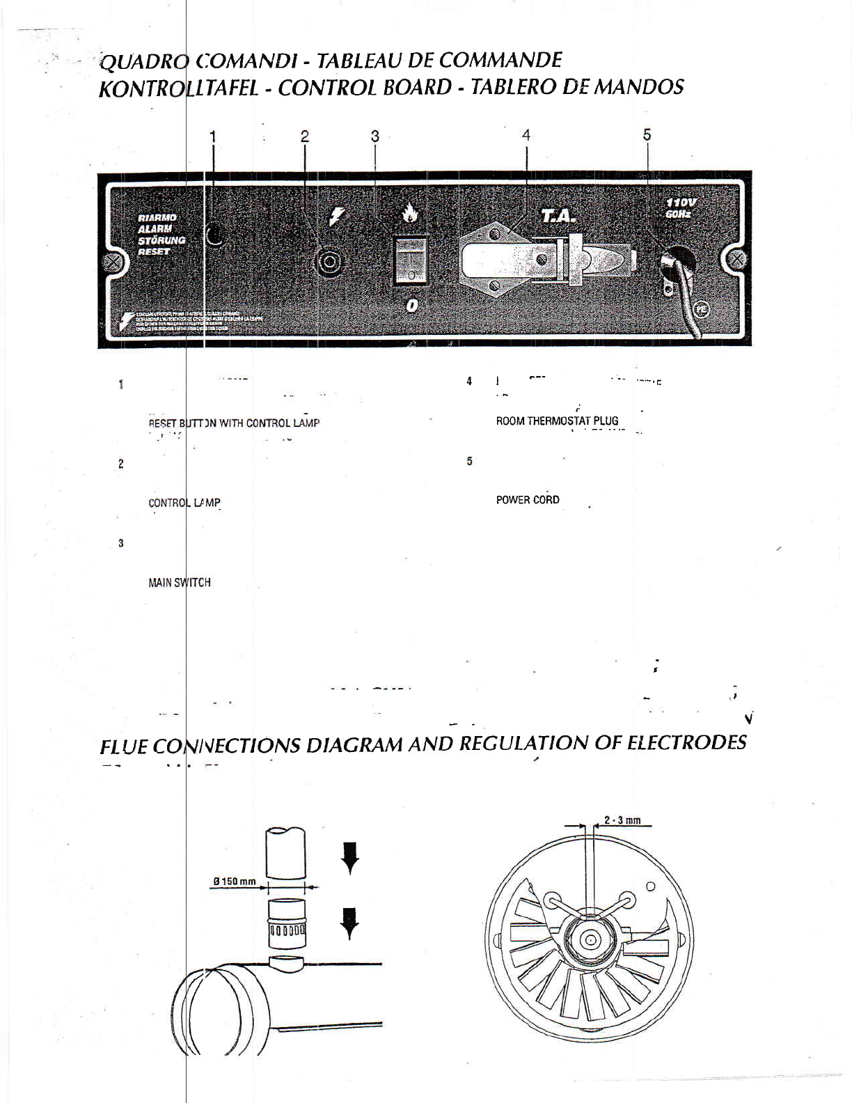
check electrode settings, adiust according to scheme "REGUI-AT|0N
OF ELECTRODES".
GE and EC
heaters produce
tion to canalise the
Awalffo-ttow
. Make sure
. Make sure
the heater
and animals
. Unpluo
cedure once or
Should the
reset button (1)'
Should the
SERVED FAUL
STOPPING
Set main
control device on
SAFETY
The unit is
malfunction this
the pilot lamP in
Heaters are
trol box before
. Read and lhis owneis maflual before usino the heaten
. Use only in I free of flammable \apours or high dust contenq
in immediate proximity of flammable materials.
. Never use
Minimum ce 2"50 m;
vented order to avoid carbon monoxide poisoning;
ir tet (reaQ or air outlet (front);
. Never block
. ln case ol low temDeratures add kerosene to the heating oil;
, Make sure 'is atways under surveillance and keep children
I from it:
. Before tl e heater dways check free rotation of ventilator;
wlren not in use.
Warning
OPERATION
Before anY I of starting the heater is made, check that your
ms to the data on the model Plate.
t be fitted with a thermo'magnetic differeF
nust be linted to a sockel with a mains
electrical suPPlY
The heater ru r automatically when connected to a control de-
vice such as
connectors 2 and rsllt, time clock. Connection of control is made at
ol the plug (2) fitted to the heater after having re'
moved the be ween 2 and 3 as fitted ex works. This bridge
ret'ofitted if manual running of heater is whished at
should be kept
an0ther time.
To start , cc nnect to mains, set control device at desired val-
ue, set switch (3)
lowed by ignition. trosition 6: the ventilator starts, immediately fol-
n unit is started tor the first time or is started al-
ter the oil tank b( en totally emptied, the flow 0f oil to the burner
a r in the circuil ln this case the control box will
may be irnPaired
cut out the heatet it might be necessary to renew the starting pro-
t y depressing the reset button (1 )'
Mains
tial su
Unit r
crntrol box resel button (1) will light up-
equipped with an overheat thermostat safety cut
out which will tlre heater in case of overheating. This thermostal
will reset y butyou will have to depress button (1) 0n con'
lble to restart the heater.
TRANSPOR
aking any attempt to restart heater find and
reason ol ovelheating.
Warning Bel

. OBSERVED FA
o
. Molor does nol
. Motor shns, rgn
. Moior statls,
Heater does st,
' Motor do€s s(
lf heater still
CAUSfSAND REA4EDIES
IED FAULI o{t/sf REMEDY
no igni[on
llo el€ctrical curent
Gheck majns (should be 110 V - 1- - 60 Hz)
. Crreck proper poStioning and tunctoning ol
snitch
Chect fuso
, Wrong setting ol rmm helmoslit 0r othe,
conlrol
Check correct setting ol heaEr control'
lf herm0sEL make sure sslecled temperature
is hioher han rootn tempelatute
Thermostat or other conuol delclive ReDlacs conttol devtce
Electdcal motor delective ' Reolace electricd motot
' Eleclrical molor beadnos deleclive ' Replace electrical motor bearinqs
Eurned out condenser Replace condenser
ion or cuts oui
emits smoRe
Bectlic ignitor detedive
Checfi connectiol ol H.T. leads t0 eleclrodes
and translormer
Check electrodes setling (see sch€me
. REGUTATION OF RECIRODES')
'Cted( elecfodes lor cleatlliness
ReDlace ltT. translormer
Rame control box defective Eeolace conttol box
fnotocell detective Clean or replact Photocsll
, Not enough or no luel at dl at burner
'Check stale of motor-pump plaslic coupling
. Ctre,ck fud line syslem includino lual lilter lor
oossible leaks
Cle:n or reDlace oil nozle
Solenoid defective
Ctreck electrical coonec[oo
Check thetmostal ll
. Clean or replace solenoid
Not enough combustion air
Make sure air inlet and oullet are lreo
Check sening ol combustion air llap
'Chan bumer disc
'Too much combustion air . Check sening 0f combustion air llap
Fuel contaminated of conlains walel orain fuel in lank with clean luel
Clean oil liltel
' Air leak in fud circuat 'Check fuel line and filter lor possible leaK
Not enough fuel at burne(
Check pumP Pressure
. Clean or replace luel node
Too muci tuel at burner
Check 9umP Pressure
Replace nozle
I
p
. Solenoid deteclive Re9lace solenoid coil or complets sol€noid
. Ventilation thelmostat delective Replace FA themosht
'kino properg, please re4lert to nedest auhorized dealer'
11

50Hz
60Hz
tl
0l,
0U
t
I
?
I
L
11
11
ui
I
I
I
I
I
I
-. r.t I LLL I lfl\-t./
T
rA
tl- | 2l I { 5 6 t I e r0 tl
I
oo rl
LOAU4 - _ AL
[!il'r?';'Ecoolror
t l, /u. 120 A
rll-
FAN THERMOSTAT
c0
CONOEilST-R
MVr
.rtl i
BOOM THERMOSTAT PLUG
BEI.AY
RE
AP
RFST
FAN MOTOR
ELECTRIC PILOT I-AMP
SWITCH
CONTROL BOX
HEATED FILTER
t. :
!
I
lomomL
-t
IN
14

ADVANCED
Motor and
Causes:
1.lnconectorlow
2' Fuse in heater is
3. Thermostat
4. Contrclboard is
5, Reset button has
Solutions:
1. lnconect or low
measure volts can
extension cord (s)
2. Fuse in heater is
probe on each end
possible causes.
great lf the supplied
3. Thermostat is
set a multi-meter to
4. Confolboard is
voltage's reaclring
5. Reset button has
Motor does not
Causes:
1. Conbolboard is
3. Motor start
4. Fiiel pump seized
Solutions:
1. Controlboard is
check tur
2. Motor is
3. Motor start
tor by momentarily
multi-meter should
he pump has lf the fan blade is still difficult to tum, the motor is defective'
2. Motor is defeclive,
UBLESHOOTING
r lo not operate.
r supplied to the heater.
t.
rr not fumed up to call for heat.
Me.
b een reset.
r supplied to the heater. Most indirect oil heaters require a minimum of 108 volts to operate propeily. A multi-meter set to
d to check the amount of voltage at the end of the extension cord(s). lf he measured voltage is too loq the length of the
b e shortened or a hicker gauge extension cord must be used.
r. Locate and remove he inline fuse of tre heater. Set a multimeter to measure ohms of resistance. Place a multi-metet
the fuse. The multi-meter should read zero ohms (continuity) or the fuse is blown. lf a new fuse blows immediately, check for
f lr inconect voltage to he heater. Make sure the total amperage draw of all equipment running on he circuit is not too
rge and total amperage draw are corecl, check the wiring in the heater for corectness and possible shorts,
r or not tumed up to call for heat Tum the thermostat up to the highest possible setting and try to start the heater. Next
ure voltage coming out of 0re thermostal lf approximately 120 volts is not measured, the hermostat is defective.
ve. Using a multi+neter set for rrolb, drec* tre hot and neutal riires which bring voltage into the contol board. lf proper
il ard then the control board is defective,
b een rcset Push the reset buton and try to start the heater,
brI ignition sparlt is prcsent
Me.
is defective,
ive.Locate he terminals of the onfol board that connect to the motor wires. Use a multi'meter set to read voltage and
, 20 volts to the motor when the heater is tumed on. lf no voltage is observed Sre control board is defective.
tt e confol board and the motor start capacitor check ok and the fuel pump is not seized, the motor is defective.
i: r defective. The capacitor may be tested using a multi-meter set to the towest possible ohm range. First "shorf fre capaci-
in g a screwdriver across the two capacitor terminals. Then place the multi-meter pmbes on the tv'/o capacitor terminals' The
r l-ose to zero ohms (continuity) firit fren slowly move to infinity on the multi-meter. lf not fren the capacitor is defective.
Wilh the heater unplugged, stand behind the heater and attempt to tum the fan blade clockwise by hand' ll the fan blade is
he :onnection between 6re motor shaft and the pump shaft Attempt tuming the fan blade again. lf the motor now fums freely,
4. Fuel pumP seized
dificult to tum, undo

Motor runs, spart
CaIses:
1. Spray nozle
2. Fuel pump is
3. Air entering the
4. Solenoid valve is
5, Conbol boad is
6. Fuelfilter is dirty.
7. Safety thermostat
8. Air proving switch
Solutions:
'1. Spray nozzle
as this may enlarge
2. Fuel pump is
fuelpump. Use a
to set the pump
nection and place a
and he fuel pump
necessary The fuel
3. Air entedng he
make sure all
inlet line untilfte air
raher than he fuel
4. Solenoid valrre is
voltage to he
noid valve is
proper voltage is
5. Contol board is
vafue wires connect
6, Fuel filter dirty.
located where the
7. Safety
bol board and the
Use a multi-meter
infinity (no
8. Ak proving
board and the
powerto $e
switch to the
conhol board is
prlsent, but there is no fuel spray
/or broken pump coupling
$ mp thru the inlet line.
;tive.
ive.
ctive or tdpped or improper duc'ting.
ctive.
Rernove and inspect the spray nozle. Clean or replace as needed. Do not clean the nozzle orifice with anything metal
rifice.
, The ouput pressure of $e fuel pump can be checked by placing a high pressure fuel gauge into the gauge port of the
Mth enough capacity to measure he high pressure your particular heater can produce. Use the adjushnent on the pump
to lhe manufacturer's specification. lf pu do not have a fuel gauge, you may slightly loosen the pump's ouput line con-
t rere. Run the heater brieffy and see if fuel reaches he rag. lf no fuel is pumped, check the connection between the motor
re sure the motor can fum tre pump. Also check the extemal and intemal fuel fittes fol blockage, and dean or replace if
rc intemal filter is usually located vfierc $e fuel inlet line enters the pump. Check to make sure motor is rotating pump.
l ump trru the fuel inlet line. lf air enters tre pump it will lose its prime and will not maintain adequate pump pressure. First
inc uding he tuel filter on tre inlet line are tighL lf you still suspect air is entering fie pump, start eliminating prtions of fie
is found. Start this ptocess at tre fuel tank end of the inlet line. lt may be necessary to draw fuel from a small container
;tive. Use a multi-meter set to measure rrolts. Check for approximately 120 volts at $e ends of the two wires $at carry
virlve; lf proper voltage is read, try deaning the valve if it is dirty. lf the vafue will not open fully to allow fuel spray, the sole
lf proper voltage is not read, check for voltage on the contol board terminals that the solenoid vafue wires connect to. lf
tre solenoid vafue wires are defectirre. lf voltage 'rs not read on the board terminals, the control board is defective.
ive, Use a multi-meter set to measure voltage, Check for proper voltage on the two board terminals that he solenoid
liproper voltage is read, the contol board is ok. lf proper voltage is not read, the control board is defeclive.
the extemal and intemai fuelfilten and clean or replace as necessary. Most fuel pumps contain an intemalfuelfilter
lirre enters the fuel pump.
rtive or tipped, Also called overheat switch. Some indirect oil heaters have a safety thermostat wired betvtreen the con-
id valve. lf the heater bemmes too hot tris normally closed switch will open and intemlpt power to the solenoid valve.
to neasure ohms. Place the multi-meter probes on the trlo male terminals of the safety thermostat. lf the multi-meter shows
the safeg thermostat is defective. lf he switch opens up before the heater becomes hot the safety thermostat is defective.
d efectjve, Try to start tre heater without duciing. Indirect oil heaten have an air proving switch wired between fte confol
v alve. The air proving switch is normally open and requires air from the tuming fan blade to close the switch and send
Va ve, Set a mult-meter to measure voltage, With ttre fan blade tuming, check for voltage coming out of the air proving
ya ve. lf no voltage is read, next check {or volbge at the conbol board terminals out to the air proving switch. lf voltage at the
lhe air proving swttch is defective. lf no voltage is read at the board, the control board is defective.

ftfrotor runc fuel
Causes:
1, Electrodes
2. Transformer
3. Conbol board
Solutions:
1. Elecfodes
Gheck the eledrodes
2. Transformer
a good ground
mately 120 volts. Do
tested for proPer
3. Contol board
to the hansformer. lf
Motor run$ fuel
Causes:
1. Pump Pres$re
2. Etecbodes
3. Nozzte dirty or
4. Ah damper seting
5: Transformer
6. Ducting is i
7. Venting is
8. Fuelontalns
Solutiom:
1. Pump prcssure
ment to set he
2. Elecfodes
Check the
3. Nozzle dirtY or
enough use, fuel
or replace the
4. Air damper
5. Transformer
6. Ducting is
7. Venting is
tut no spark is observed
or llapped inmnecily.
ar;.
or lapped inconectly. Inspect tre elecbode tips for melting. Make sure there are no.cracks in the porcelain insulation'
ith ire manufacture/s specifications for gapping and spacing. Adjust or replace the electrodes as needed'
. I ransformers requirc a ground conneclion to function properly. Check the transformer's ground wire or mounling tabs for
n, Use a multi-meter set to measure voftage. Check the voltage in to lhe bansformer from the conhol board for approxi-
a tempt to measuG the tansbrmer's output vottage with an ordinary multi-meter. The tansformer may also be bench
use a multi-meter set to measurc voltage. Take a voltage reading on the controt board terminals that send input power
tvoftage is not present, Ure contol board is defective'
spark is presen! but heater will not ignite
t
or gapped inonecdY.
inipnect
v eak,
as 'teeded.
is irrcorrecl use the manufacturcrs specifications for the air damper setting and adjust m needed'
is rueak. Remorre the tansformer and perfom a bench test
F rllow the manufacturer's recommendations conceming maximum duc{ length and diameter'
Fntaminants.
;L Using a high pressure fuel gauge, ctreck dre ou$ut pressure of fre fuel pump' lf necessary' use'the pump's adjust
;sure to the manufacturer's specificatjons'
o'gappedinmrrectly.lnspecttree|ecbodetipsformelting.Makesuretherearenocracksintheporce|aininsu|ation.
itlr he manufacurers specmcations for gapping and spacing. Adjust or replace the elecbodes as needed'
( lean tre nozle using compressed air. Never use anything metal to clean the nozzle as ttris may enlarge the orifice' with
n 1 under high pressure frru fre nozle orifice can enlarge ire onfice' This is especially true wtren diesel fuel is used' Clean
: F tllow the manufaiturer's guidelines for venting'

Heater ignites,
Causes:
1. Photocell is dirty,
2, Contol board is
3. Fuel pump
4. Fuel fitter dirty.
Solutions:
1, Photocell is dirty,
with a soft, dry doth,
eiher replace the
2. Confol board is
bustion flame has
3. Fuel pump is
pressure wih a
4. Fuel filter dirty.
Heater ignites,
Causes:
1, Fuelpump is
2. Solenoid valve is
3.Overieat
4. Duc{ing is
5. Venting is
6. Nozle is dirty.
7. Fuel filter is dirty.
8. Gonbol boad is
9. Fuel contains
Solulions:
1. Fuel pump is
pressure with a
2. Solenoid valve is
and the solenoid
3. Overheat
sure ohms of
probes on fie tvro
Remember that if
heat enough to shut
4. Ducting's
regarding maximum
and shuthe heater
les; than one minute and shuts doum
igned or defective.
ive.
igned or defective. Check that 0re photocell 'rs aimed conecUy and is free of dirt. lf necessary, clean the photocell "eye"
rtunately no test exists for the photocell. Aftempting to lumper out" the photocell will not test the function. You must
ill or bonow a knorvn functioning photocell from an identical heater.
ive. lf the heate/s spray and spark are conect the photocell and control board must work together to rectgnize the com-
: established. Therebre if a new photocell does not conect this symptom, the control board is defective,
lf the fuel pump will not achieve or maintain pmper o@ut pressure, the fuel pump is defec'tive, Check the pump's ouQut
the intemal and extemal fuel flters and clean or replace as needed.
eral minutes. then shuts down
tive.
is defective,
ve.
contaminants.
lf the fuel pump will not achieve or maintain proper ouput pressure, the pump is defective. Check the fuel pump output
[ve. Use a multi-meter set to measure voltage. Check for proper voltage at tre solenoid valve. lf proper voltage is read
wi I not stay open and allow fuel spnay, the solenoid valve is defective.
is defective. Also called a safety trermostat or limit switch. Some heaters are equipped with this. Set a multi-meter lo mea
Perform this test immediately after the heater shub down and the overtreat trermostat is still hot. Place he multi-meter
trrrminals of the safety thermosht lf tre multimeter reads infinity (no continuity) the safety thermostat is defective.
ter is over firing due to high pump pressure, wom nozzle, or is improperly ducted or vented, the safe$ lhermostat will
I eater 0fi.
Al rvays follow fte manufacfure/s recommendations
length and diameter. Failure to do so can result in heat building up in the heater until the safe$ thermostat contiacts open

5. Venting is
heater untilhe
6. Nozle is dirty, lf
clean the nozle as
7. Fuel filter dirty.
8. Conhol board is
solenoid valve. Using
components.lf proper
9. Fuel ontains water
Heater igniteq but
Causes:
1. Fuel pump pressure
2. Nozle dirty orwom,
3, Elecbodes
4. Fuelfilter is dirty.
5. Air damper sefling
6. Whirl disk dirty or
7, Ducling is impmper.
8. Venting is improper.
9. Fuel contains water
Solutions;
1. Fuel pump prcssure
of the fuel pump. Use a
pump to set he pump
2.Node dirty orunm.
enough use, fuel
or replace $e nozzle
3. Elecbodes damaged
Check the electrodes
4. Fuel filter is dirty.
5. Air damper setting
6. Whirldisk dirty or
7. Ducling is improper.
8. Venting is improper.
I Frrel rnnlains unter crnfaminenls \fisrrallvinsncclthcfiralinthntankfnrwatcrnrrnntaminants llrain flrrsh and ra-fill tankesnaadod
Fo low the manufacturer's recommendations conceming proper venting, Failure to do so can result in heat building up in the
her mostat contacts open and shut he heater 0fi.
reiches he nozzle, $e sp|?ly can be adversely afected and c€tuse a shut down. lf possible obserrre the spray pattem and
ded.
tl e intemal and extemal fuel flters. Clean or replace as needed.
ctit e' For the heater to function, he conbol board must send proper voltage to three components: motor, lransformer and
mt lti-meter set to measure voltage, check tre appropriate control board terminals for proper voftage out to these three
tge to any of these thrce aomponenb is not observed, he control board is defective.
c lntaminants. Visually inspect tre fuel in the tank for water bubbles or contaminants. Drain, flush, and refill as needed.
Etion is p(x'l or uneven
inconect
gapped incorecfly.
rct.
tned.
co ntaminants.
in ored' The ou$ut pressul? of tre fuel purnp can be checked by placing a high pressure fuel gauge into fre gauge port
au p with enough capacity to measure the high pressure your particular heaterian produce. Usi tli adjustneit on the
:e n.the nozzle using compressed air. Never use anything metal to clean the nozzle as his may enlarge the orifice. With
uttder high pressure hru the nozle odfic€ can enlarge tlre odfice. This is especially tnre wtren diesel fuel is used. Clean
ure to he manufacturefs specifications.
ded.
gitpped inconectly. Inspect the elecirode tips for melting. Make sure there are no cracks in the porcelain insulation.
th e manufacturer's specifications for gapping and spacing. Adjust or replace the electrodes as needed (page 5/17).
he intemal and extemal fuet filters and clean or reolace as needed.
;l Use the manufaciureds specifications for the air damper setting and adjust as needed. (see Diagram B, page 17)
led. Inspect the whirl disk and clean if necessary. lf tre disk is waped or mis-aligned, replace or adjust as needed.
r the manufacturer's recommendations conceming maximum duct length and diameter.
t the manufacture/s guidelines for venting.

Heater igmites bur fian e is excessive
CauSes:
1. Fuel pumppresrfre i; too high,
2. Nozle is umm.
3.Incorrectfud.
Solutions:
1, Fuel pump
especially tue wfren
safety trermostat ca rse e shutdolvn.' Replace after 400 hours of operation.
;liil9j' ll?*, ffig|:::,*:'lg:lln.r_rler,rrisrr nle.s.sr1re th r the nozzte orince ,.n .nr.,ge t e
,'f"'iiXij:*f H1i*1fi:ilf*:^T_q?pgtffi.ii;#'##j'ffi;;,ffi.T,".i','ffi,T'"'h:i:';:
the odfice. This is
3. Inconed fuel.
manufacfure/s
susped the:fuelis
::lt :::: i
k too high' Attach a high pressule fuel gauge to tre fuel pump and check the pump pressure. A-djust tle pressure to lhe
a lons with the adjustment on the fuel pumpi
H:Jt"ffi'J:ffIffiTlE#tflff*#:H:usesasorine, painturinner, sorvenb, orohernammabreriquids. rf you
No2le Pump pressure
[barf / [psl
-_ Danfoss 0,55 800 w13,5 / 196
Delavan 1.10 800 w12 t 174
Delavan 1.50 800 wP1: 8 / 116
P2:20 l29O
Delavan 2,00 80'w P1:8,5 l'123,3
P2:12 1174
This manual suits for next models
2
Table of contents
Other Cantherm Heater manuals
Popular Heater manuals by other brands

Toyostove
Toyostove RSA-10 Operation and maintenance instructions

flowair
flowair LEO EL S BMS Technical documentation operation manual

Pelonis
Pelonis HC-1010 owner's manual

Honeywell
Honeywell HZ-1350 Series Important safety instructions

Gasmate
Gasmate AH1069ODS instructions

BRAYER
BRAYER BR4800 instruction manual