114605-001 - Product Manual - #1557 Infrared Construction Heater - Revision 09 - 11-11-2014 Page 7
2.0 - Introduction & Product Information
Congratulations on your choice of a Pelsue Model #1557 Infrared Construction Heater. The Pelsue Infrared Heater is
specically designed to provide means of heating ventilated shelters or work areas. Such use includes, but is not limited
to Fire, Police & Hazmat response crews in bio-terror and mass casualty incidents. This equipment has been designed
and manufactured to exceed durability requirements in order to meet the needs of the discriminating operator. Safe,
efcient and trouble-free operation and maintenance of the system requires that anyone who will be operating, main-
taining, or inspecting the equipment, read, understand and follow all the operation, safety, maintenance, and inspection
instructions contained within this manual. This manual covers the Pelsue Model #1557 Infrared Construction Heater.
Use the Table of Contents as a guide to nd specic information.
Keep this manual available for future reference if required, and as a tool in the training of new operators.
This product is part of a system indented for usage
in a climate control scenario. The user must read,
understand and follow the instructions contained in
this manual before using this equipment. Failure to
follow these instructions could result in serious injury
or death.
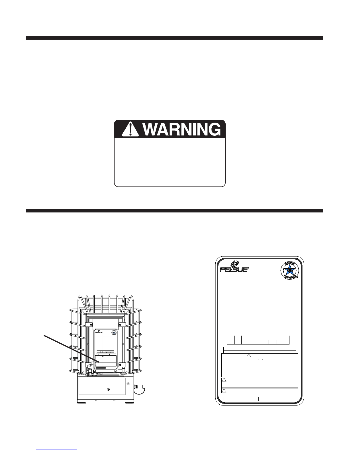
2.1 - Serial Number
Always give your dealer the serial number of your Pelsue portable infrared heater product when ordering parts or request-
ing service or other information.The rating and serial number decal is permanently embossed with a serial number. The
serial number decal is located on the rear heat shield as shown in
Fig. 2a
. The serial number decal will appear as shown
in
Fig. 2b.
A space has been provided below for the recording of the serial number for future reference.
Figure 2b: #1557
Serial Number Decal
MODEL:__________________________________________
Serial Number :_____________________________________
#1557
SERIAL
NUMBER
LOCATION
Figure 2a: Serial Number
Location
NOTES:
MATERIAL: AVERY PX 2071-P/905-MATTE CHROME POLYESTER FILM,
.002 THICK WITH HIGH TACK PERMANENT ACRYLIC ADHESIVE
IAW-UL FILE MH-11912 (N) CAT. PGGU2
**THE TEXT: "1557- " IS TO BE IMMEDIATELY FOLLOWED BY
A SERIAL NUMBER STRING EACH DECAL BEING UNIQUE SERIAL NUMBER
DETAIL: CSA LOGO ARTWORK
SCALE 2 : 1
NOTE:
COLOR BLACK: ROUND BORDERS, STAR BORDER
LETTERING & CSA LOGO
COLOR BLUE: INSIDE OF STAR BORDER
SCALE 2 : 1
DETAIL: PELSUE LOGO ARTWORK
NOTE:
COLOR BLACK: ENTIRE LOGO
BTUH
NO.
1557
MIN.
BTUH
INPUT INPUT
1557-
350 PSI
P/N 114609-001
ENG :\
CHAU 08-2 2-11
DRI V E :
250 0 SOUTH T EJON S TREE T
ONEWITHOUT THE PERMISSIONOF THE T.A.PELSUE COMPANY."
SCALE 1:1
DO NOT SC ALE DRA WING
TRE A T M E N T
UNLE SS OTH ERWI SE SPE CIFIE D
TOLERANCE S ARE:
DIMEN SIONS A RE IN INC HES
FI NI S H
PAR T NU MB E R
DA T E TITLE
APP R O V AL S
CO N T R A C T NO .
DR A W N :
08-25-11DU K E
TO B E REPR ODUC ED, US ED, OR D ISCL OSED I N WHOL E OR IN P ART TO A NY-
ENG LEWO OD, CO LORA DO 8011 0 USA
SHE E T
FS C M NO . DW G . NO . RE V .
114609
114609-00 1
PLA TE DE CAL - I. D. & SE RIAL #
HEA TER O PERA TING I NSTR UCTI ONS
#15 57 CON STRU CTIO N HEAT ER
B
1 0F 1
05
O:\P ortab le\Dr awing s - Porta ble\11 4609. SLDDR W
NO N E
REF ER TO N OTES
06- 09- 95
SI Z E
0.010
PO RT AB LE
"T HIS DO CUME NT AND T HE DAT A DISC LOSE D HERE IN OR HE REW ITH IS N OT
REV IS I O N :
LAT E S T
F. K. H OWEL L
FRACTIONS DECIMALS ANGLES
1/16 X.XX 0.03 2
X.XXX
CHE C K E D &
REL E A S E D :
ZONE REV. DESCRIPTION DATE B Y
00 ISSUED FOR FABRICATION 09-06-95 HOWELL
01 TEXT UPDATED 10-09-95
02 NEW CSA LOGO. WAS B-SIZE DRAWING 07-25-01 D. HAM
03 CHNG. WORD PUSHING WAS ROTATING, CHNG.
WORD BUTTON WAS KNOB. LINE #4 02-04-02 D. HAM
04 CHNG. WORD BRASS WAS RED, LINE 4 & 5 LINE 4
LEFT WAS RIGHT & RIGHT WAS LEFT 12-02-05 D. HAM
ALL 05
DRAWING REVISED, REMOVED REFFERENCE TO
QUICK CONNECT FITTING, REMOVED
REFERENCES TO "BRASS" BUTTON
08-22-11 CHAU
NOTES:
MATERIAL: AVERY PX 2071-P/905-MATTE CHROME POLYESTER FILM,
.002 THICK WITH HIGH TACK PERMANENT ACRYLIC ADHESIVE
IAW-UL FILE MH-11912 (N) CAT. PGGU2
**THE TEXT: "1557- " IS TO BE IMMEDIATELY FOLLOWED BY
A SERIAL NUMBER STRING EACH DECAL BEING UNIQUE SERIAL NUMBER
DETAIL: CSA LOGO ARTWORK
SCALE 2 : 1
NOTE:
COLOR BLACK: ROUND BORDERS, STAR BORDER
LETTERING & CSA LOGO
COLOR BLUE: INSIDE OF STAR BORDER
SCALE 2 : 1
DETAIL: PELSUE LOGO ARTWORK
NOTE:
COLOR BLACK: ENTIRE LOGO
BTUH
NO.
1557
MIN.
BTUH
INPUT INPUT
1557-
350 PSI
P/N 114609-001
ENG:\
CHAU 08-22-11
DRIVE:
2500 SOUTH TEJON STREET
ONE WITHOUT THE PERMISSION OF THE T.A. PELSUE COMPANY."
SCALE 1:1
DO NOT SCALE DRAWING
TREATMENT
UNLESS OTHERWISE SPECIFIED
TOLERANCES ARE:
DIMENSIONS ARE IN INCHES
FINISH
PART NUMBER
DATE TITLE
APPROVALS
CONTRACT NO.
DRAWN:
08-25-11DUKE
TO BE REPRODUCED, USED, OR DISCLOSED IN WHOLE OR IN PART TO ANY-
ENGLEWOOD, COLORADO 80110 USA
SHEET
FSCM NO. DWG. NO. REV.
1146 09
114609-001
PLATE DECAL - I.D. & SERIAL #
HEATER OPERATING INSTRUCTIONS
#1557 CONSTRUCTION HEATER
B
1 0F 1
05
O:\Portable\Drawings - Portable\114609.SLDDRW
NONE
REFER TO NOTES
06-09-95
SIZE
0.010
PORTABLE
"THIS DOCUMENT AND THE DATA DISCLOSED HEREIN OR HEREWITH IS NOT
REVISION:
LATEST
F. K. HOWELL
FRACTIONS DECIMALS ANGLES
1/16 X.XX 0.03 2
X.XXX
CHECKED &
RELEASED:
ZONE REV. DESCRIPTION DATE B Y
00 ISSUED FOR FABRICATION 09-06-95 HOWELL
01 TEXT UPDATED 10-09-95
02 NEW CSA LOGO. WAS B-SIZE DRAWING 07-25-01 D. HAM
03 CHNG. WORD PUSHING WAS ROTATING, CHNG.
WORD BUTTON WAS KNOB. LINE #4 02-04-02 D. HAM
04 CHNG. WORD BRASS WAS RED, LINE 4 & 5 LINE 4
LEFT WAS RIGHT & RIGHT WAS LEFT 12-02-05 D. HAM
ALL 05
DRAWING REVISED, REMOVED REFFERENCE TO
QUICK CONNECT FITTING, REMOVED
REFERENCES TO "BRASS" BUTTON
08-22-11 CHAU