Pelsue 1557 Manual

OPERATING AND MAINTENANCE INSTRUCTIONS
114605-001
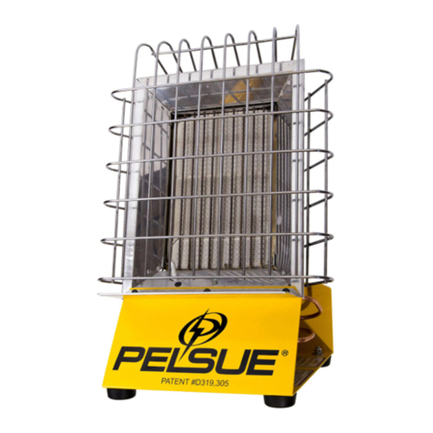
MODEL 1557
INFRARED CONSTRUCTION
HEATER
(U.S. Patent #D319,305)
TABLE OF CONTENTS
SECTION Page No.
1.0 GENERAL & SAFETY WARNINGS 2
2.0 SPECIFICATIONS 2
3.0 DESCRIPTION 3
4.0 SAFETY FEATURES 3
5.0 SPECIAL PROCEDURES 4-5
6.0 OPERATING PROCEDURES 5-6
7.0 CARE, MAINTENANCE & SERVICE 6-7
8.0 TROUBLESHOOTING 8-9
9.0 ASSEMBLY DRAWING & PARTS LIST 9-11
10.0 ACCESSORIES 11
T. A. PELSUE COMPANY
2500 S. TEJON ST., ENGLEWOOD, CO. 80110
Phone: (303) 936-7432 or (800) 525-8460
Fax: (303) 934-5581
1 Rev.#7 11-01-06

PELSUE MODEL 1557 INFRARED CONSTRUCTION HEATER
! WARNING !
Read instructions carefully before attempting to install, operate, or service the Pelsue
Construction Heater. Failure to comply with these warnings and instructions, and those
on the heater, could result in personal injury, death, fire, asphyxiation and/or property
damage. Retain these instructions for future reference.
The following information should be reviewed before operating this unit.
1.0 General & Safety Warnings:
1.01 This manual covers the description, operation and maintenance of Pelsue
Model-1557 Infrared Construction Heater.
1.02 Only personal that can understand and follow the instructions should use or
service this heater. If you need assistance or heater information such as
instructions, manuals, labels, ect. please contact customer service.
1.03 This heater is specifically designed to provide a means of heating ventilated
shelters or work areas. The use of this heater must require good ventilation.
1.04 WARNING Not for home or recreational vehicle use. Not for use in aerial
Bucket trucks. For your safety do not use this heater in a space where gasoline
Or other liquids having flammable vapors are stored or used.
1.05 WARNING Heater produces radiant infrared heat and has an open flame. Keep
solid combustibles, such as building materials, paper or cardboard, a safe distance
away from the heater as recommended. Never use the heater I spaces which do or
may contain volatile or airborne combustibles, dust particles, paint, paint thinner,
solvents or unknown chemicals.
2.0 Specifications:
Length: 13.00” (33.02cm)
Width: 11.50” (29.21cm)
Height: 20.00” (50.80cm)
Weight: 12.25 Lbs (5.56kg)
Rating: 12,000-16,000 BTUH
Manifold Pressure: 4.5-11” wc (2740pa)
Orifice size: .046” Dia. (1.2mm)
*Altitude: 0-4500 Ft. (Canada)
*Altitude: 0-2000 Ft. (U.S.A.)
2 Rev.#7 11-01-06

3.0 Description:
3.01 Each heater assembly consists of a rugged lightweight aluminum housing and
Base. Rubber feet on base provide stability & shock resistance.
3.02 A chrome plated wire basket guard with carrying handle protects both worker and
heater.
3.03 A Secondary propane regulator, mounted in heater base, is UL listed.
NOTE: This regulator is factory pre-set and lacquer sealed for optimum
performance. Any further adjustment is not necessary and could result in fire,
personal injury, and property damage or warranty invalidation.
3.04 Heater is equipped with a safety shut-off valve, CSA & CGA listed, to protect
against flame out or tip over. The rotary valve adjust from OFF, LOW to HIGH
heat settings.
3.05 Ignition is done by a piezoelectric plunger type spark igniter system for instant
firing of burner. No external power source is required. A hole in the reflector is
provided for manual backup lighting of burner with a match.
3.06 Burner is of durable ceramic, infrared high efficiency, with heat enhancer rods and
a polished aluminum reflector. This unique combination provides clean radiant
heat economically.
4.0 Safety Features:
4.01 Protective wire guard protects user from burns.
4.02 CSA Listed Propane safety valve shut-off valve works on millivolt controlled
shut off valve operating with a thermocouple sensor. As an added feature
the valve provides tip over protection by shutting off the flow of fuel to the
burner head.
4.03 Easy access to controls from back side of unit, reducing possibility of user burns
from ignition flare-up.
4.04 Safety labeling provided on heater.
4.05 CSA & CGA tested and approved
5.0 Special Precautions: ( CAUTION )
5.01 This heater is designed to function as a two-stage regulator system.
Meaning a first stage regulator is required at the bottle. Dropping bottle
pressure down to 10 P.S.I. (pounds per square inch). The regulator built
into the unit drops the 10 P.S.I down to 11” WC (water column).
3 Rev.#7 11-01-06

5.02 Make sure all L.P. fittings are tight. Use only a pipe joint compound that is
resistant to liquefied petroleum gases.
5.03 Propane bottle must be the vapor draw style, DOT (for U.S.) or CTC (for Canada)
approved 20 or 40 Lb. Gas cylinder. Do not use a forklift or liquid withdrawal
cylinder. Use only LPG (propane) fuel.
5.04 Propane is very flammable. Propane is scented and its strong odor is readily
detectable. If a gas odor is detected at any time, do not operate or continue to
operate the unit until the source of the gas odor has been located.
In the event of a leak, propane is heaver than air and will accumulate in low
areas. Never strike a match, create a spark or flame when you smell gas.
Move the heater outside and ventilate the area. Find and correct the source of the
leak before attempting to light the heater. If the leak cannot be corrected, do not
tamper with the heater. Turn the heater off and consult the manufacture or
qualified technician.
5.05 Do not lean over heater when lighting. When lighting with a match, light through
the hole provided on the side of the reflector. Do not light at orifice.
5.06 Do not move, handle or service unit while hot or burning. Permanent skin tissue
damage can occur if contact is made with the unit. Let the heater cool down after it
has been shut off.
5.07 Never direct this infrared construction heater toward any LP gas cylinder within
20Ft. The heater must be a minimum of six feet from any LP gas cylinder.
Keep away from fabric or other combustibles. Survey the work area for any
potential hazards and correct them before operation.
5.07 Unit should be used in a well-ventilated area. Provide a positive air displacement
of at least 4-CFM per 1000 BTUH of the heaters rated input.
5.08 Heater should be inspected before each use and at least annually by a
Qualified service agency.
5.09 Minimum ambient temperature for using this heater is -20°F –(29°C). The heater
Is designer for use as a construction heater under ANSI Z83.7 & CGA 2.14.
Check with your local fire safety authority if you have questions about applications.
5.10 WARNING: For the safe installation of this unit, the following table of clearances
Must be maintained.
NOTE: Clearances are established by A.N.S.I. and the Canadian Gas Association
as proper clearances to combustible such as wood, cardboard, tent fabrics etc. in
case of tip over or inadvertent unsupervised operation.
4 Rev.#7 11-01-06

Clearance to Combustibles:
Side: 18”
Rear: 18”
Ceiling: 48”
Discharge End: 48”
(FRONT)
6.0 Operating Procedures:
6.01 Inspect heater orifice, Fuel inlet and base for signs of liquid fuel or oil
contamination. If present, DO NOT USE HEATER. Have a qualified technician
disassemble LPG supply line and components to remove liquid fuel or oil before
use.
6.02 Place heater on secure level surface. Heater must be positioned such that it is not
directly exposed to wind, water, spray, rain and/or dripping water.
6.03 Connect LPG supply hose with first stage regulator assembly to a 20 or 40 LB.
approved cylinder. (First stage regulator should take bottle pressure down to
10 to 35 PSI.) Connect to heater by either a quick disconnect fitting or 9/16”
Left Hand threaded fitting. Tighten all connections.
Locate LPG gas cylinder at least 6Ft. from heater, in a position away from the
Direct path of radiant heat from the heater.
6.04 Turn on the fuel at cylinder and recheck all fittings for possible leaks using a soap
solution. Tighten any leaks found and retest. Never use a match to check for leaks.
NOTE: the longer the fuel hose length the longer period of time to purge the hose
of air from the initial hookup.
6.05 TO IGNITE: First depress and turn rotary knob, located on the back of heater
base, too the HIGH position, first detent. Kneeling behind heater (DO NOT
STAND OVER HEATER) Second, depress and hold the brass button on the safety
shut off valve located under the heaters ceramic head in the middle of the base.
While still holding down on the brass button, push down on the igniter button
repeatedly until the heater ignites. Continue holding the safety valve button in for
approximately one minute to heat the thermocouple. When the thermocouple is hot
enough, release the safety valve button and the heater will stay lit. If the heater
goes out, turn off the fuel valve and the tank valve and wait for five minutes and
repeat lighting procedure.
6.06 Alternate lighting procedures: A long match may be inserted through the opening
in the heater shield on the left side in lieu of the piezoelectric igniter while observing
all other safety precautions. Once the heater has been lit, you can adjust the heat
output to the desired setting.
6.07 To turn heater off: First turn off the fuel supply at the bottle. This burns off excess
fuel in the supply hose and lowers line pressure. When the heater flame goes out,
turn the rotary knob to the off position. Let the heater cool down and you can
5 Rev.#7 11-01-06

disconnect hoses and store away. NOTE: The unit must not be relit for 5-minutes
after a shut off. Follow paragraph 6.05 to reignite.
6.08 In the event heater is inadvertently tipped over while operating, the gas flow will be
cut off by the safety ball check valve. To reignite you must first stand heater
upright. Then to release the safety ball check valve, you must turn off the rotary
valve on the back of the heater and fuel cylinder, wait 5-minutes, then turn valves
on again to reset for ignition. If heater still will not ignite, see Restart Trouble
Shooting (see Dwg. #109207) for further instructions.
6.09 Use of the heater in a drafty area may result in a loss of heater efficiency.
Operate the unit in a draft free area or turn the back of the heater into the wind.
6.10 NOTE: The hose assembly shell be visually inspected prior to each use. If it is
evident that there is excessive abrasion or wear, or the hose is cut, it must be
replaced prior to heater operation. The replacement hose assembly must be that
specified by the manufacture. See parts list.
6.11 When a heater is installed or stored indoors you must conform to the local building
Codes, or in there absence the current Standard for Canada or the U.S.,
CAN/CGA-B149.2 or ANSI/NFPA-58 titled Storage and handling of liquefied
petroleum gases. When stored or not in use the connection between the LPG
cylinder/bottle and the heater must be disconnected and the cylinder removed from
the heater.
7.0Care, Maintenance & Service:
7.01 Visually inspect daily for oil or liquid fuel contaminant present in the heater or fuel
supply hose. If any is evident, heater should be cleaned and or repaired by a
qualified technician before use.
7.02 If the heater has not been in service for a period of time, the following procedure
should be initiated before placing it back into operation. Use an air hose (not to
exceed 30 PSI.) Blow off any dust/dirt that has accumulated on the heater. Pass
then air hose over the entire exposed area of ceramic. Vacuuming is acceptable.
7.03 Clean the venture tube and orifice spud allowing air pressure to flow for
approximately one minute. If venture still appears dirty, remove orifice bracket and
clean with a nylon brush (toothpick, pipe cleaner) If a residue or deposit inside the
orifice spud remains after an attempt has been made to clean it, it must be
replaced with a new orifice and a tip-over ball check obtained from the factory.
DO NOT CLEAN ORIFICE WITH A DRILL OR OTHER METAL OBJECTS.
7.04 Wipe the reflector clean using a soap and water solution or a non-abrasive
aluminum cleaner.
7.05 If a malfunction in the pressure regulator or safety shut-off valve control valve is
Found after placing the heater in operation, consult the factory or an experienced
Heating contractor for repair or replacement.
6 Rev.#7 11-01-06

7.06 The Pelsue portable radiant infrared construction heater contained in this carton
has been assembled at the factory and is in operational condition without the
need of adjustment or further assembly. Alteration of the heater or replacement of
components not specified by the Pelsue Co. voids all warranties.
7.07 If additional service is required, contact the factory or distributor.
For Sales and Service Contact:
T.A. Pelsue Company
2500 S. Tejon St.
Englewood, Colorado 80110
Ph: 303-936-7432 or 800-525-8460
Fax: 303-934-5581
7 Rev.#7 11-01-06

8.0Troubleshooting:
Symptom Cause Remedy
Heater fails to light Cylinder’s gas valve closed Open valve
Manual shutoff valve closed Open valve
Excessive draft Relocate or reposition heater
Heater inlet pressure too low. Verify adequate fuel supply is
Available. Check regulator outlet
pressure 11”WC on high position
Heater safety control valve Replace
defective.
Obstruction in orifice spud Clean or replace
Spark generator wired disconnected Reconnect or replace
or grounded.
Electrode out of alignment Adjust to 1/8” from heat rods
Electrode ceramic cracked Replace
Spark generator defective Replace
Heater lights – flame Inadequate gas pressure Increase to 11”W.C. on high
Extinguishes when releasing Insufficient fuel supply Provide adequate fuel supply
Safety valve button after Thermocouple defective or loose Replace or tighten electrical
Depressing for 60 seconds. Connections
Heater safety valve defective Replace
Fuel mixture burning within Gas connection loose Tighten & check for leaks
Rayhead assembly Inlet pressure too high Reduce to 11”W.C. on high
Cracked or broken ceramic Replace rayhead assembly
Improper lighting Light ceramic burner element
& not at the orifice. See
Sec.6.0OperatingProcedure
Ceramic temperature below Orifice spud misaligned Replace orifice mtg. bracket
1700°F. (not orange in color) Obstruction in orifice spud Clean or replace
Inadequate gas pressure Increase to 11”W.C. on high
Cylinder’s gas valve not fully open Open
Manual shutoff valve not fully open Open
Kinked or obstructed fuel line/hose Straighten or clean
Ceramic separated or cracked Replace
Heater Flare-up Contaminated fuel Disassemble, thoroughly
clean unit and LPG filter
Liquid fuel reaches heater Possible overfilled LP bottle
Or using liquid withdrawal
bottle. Replace with vapor
drawstylebottle.
Wind or drafty conditions Relocate heater as so the
wind comes from behind
theunit.
8 Rev.#7 11-01-06

8.0 Troubleshooting:
Heater Extinguishes on Control valve turned beyond Adjust valve to proper range
Low setting low position.
Dirty orifice Clean orifice
Inadequate gas pressure Increase to 11”W.C. on high
position.
NOTE: If after reviewing and or identifying one or more of the above remedies, proper heater operation
characteristics cannot be obtained, consult the factory or distributor for further inspection and repair.
Improper operation may cause faulty combustion and/or fire with resultant danger of personal injury,
death and/or property damage.
9.0 Assembly Drawing & Parts List:
9 Rev.#7 11-01-06

9.01 Parts List:
Item No. Description Part No.
3. Base – Heater, 1557 as painted 114600-001
4. Heat Shield – model 1557 heater 114611-001
5. Support – heater base 114601-001
6. Panel – rear replacement 119869-001
7. Mounting bracket – rotary valve 123179-001
8. Hanger chain ass’y – w/snap hooks 109233-001
9. OPEN
10. Rayhead – ceramic element w/rods & reflector 109246-001
11. Orifice spud – Propane 16,000 BTUH 109180-001
12. Mounting Bracket – orifice spud 109182-001
13. Seat – orifice spud 109224-001
14. Safety valve – shutoff manual (brass button) 109183-002
14A. Solenoid – coil, safety valve 109184-001
15. Thermocouple – 10”Lg. Use w/non thrd. valve 109185-002
16. Brass tee – 1/8FNPT X 1/8FNPT X 1/8FNPT 32F-152200
17. Pipe plug – 1/8”MNPT, Hex hd. 109244-001
18. Valve – Rotary, high / low 123180-001
19. Knob – for rotary valve 114613-001
20. Electrode – Igniter probe 109176-001
21. Sleeve – vinyl insulation, ¼”∅x 1”Lg. 109291-001
22. Piezoelectric igniter – plunger type 109170-001
23. Wire assembly – white, 18Ga. 23”Lg. 109292-001
24. Wire assembly – black, 18Ga. 23”Lg. 109293-001
25. Nut – igniter mount 109494-001
26. Regulator – LPG, set to 11” W.C. 35G-010100
27. Nipple – Hex pipe, ¼” MNPT 107060-001
28. Nipple – Quick disconnect, 250-PSI rated 122429-001
29. Dust cap – yellow rubber 109264-001
30. Reducer bushing – hex, 3/8”MNPT x 1/8”FNPT 114621-001
31. Compression fitting – ¼” tube x 1/8”MNPT 112307-001
32. Comp. Fitting, 90°elbow – ¼” tube x 1/8”FNPT 32F-157700
33. Tubing – copper, ¼”O.D. x .032 wall 59Z-011000
34. Grille – Basket, Wire guard, nickel-plated 114604-001
35. Laminated card – 1557 trouble shooting 116051-001
36. Decal – Warning infrared construction heater 109231-001
37. Decal – I.D. Plate & serial no., model 1557 114609-001
38. Decal – Warning & instructions in French 114623-001
39. Decal – Caution do not move while in use 109232-001
40. Decal – Warning, general hazard 110292-001
41. Decal – Warning, hazardous conditions 110289-001
42. OPEN
43. Screw - #8 x 3/8”Lg. Hex Hd. Sheet metal 68N-035300
44. Screw - #10 self-tapping sheet metal 106302-001
10 Rev.#7 11-01-06

45. Screw - #12 x ½”Lg. Self tapping, hex hd. 105273-002
46. Screw – ¼-20 x ¾”Lg. Hex hd. Cap, Zn plated 101427-002
47. Pop rivet – Stavex, 3/16”∅x .06-.38 grip range 118518-001
48. Flat Washer – ¼” Type-A, Plated 100050-009
49. Lock nut – ¼-20 Hex, nylon insert 100048-114
50. Rubber foot – 1 ½” Dia. 100188-002
51. Screw - #8 x 3/8”Lg. Pan Hd. Phillips 108328-001
10.0 Accessories:
10Ft. (3.05m) LPG hose w/quick disconnects (CSA Approved) 122430-010
20Ft. (6.01m) LPG hose w/quick disconnects (CSA Approved) 122603-010
25Ft. (7.62m) LPG hose w/quick disconnects (CSA Approved) 122604-010
Regulator Ass’y – POL full flow, w/ 7/8” LH Thrd., 10-PSI Reg. 122602-001
& quick disconnect coupler for above hoses.
Regulator Ass’y – POL Hand Turn w/ 1 5/16 Acme Thrd., 10-PSI 122602-002
Reg. & quick disconnect coupler for above hoses
Regulator Ass’y – POL Excess flow, soft seat, 7/8”LH Thrd. 1590-FQ
Adj. Reg. with filter, gauge & quick disconnect coupler
11 Rev.#7 11-01-06
Other manuals for 1557
1
Table of contents
Other Pelsue Heater manuals
Popular Heater manuals by other brands

Toyostove
Toyostove DC-60 Operating and maintenance instructions

S&P
S&P EC-3N User instructions

Daikin
Daikin KEH094A41E installation manual

WarmlyYours
WarmlyYours LAVA Series installation manual

Webasto
Webasto Thermo Top V Operating and servicing manual

Zodiac
Zodiac JXi 200 Installation and operation manual