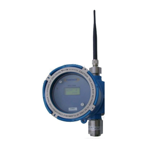
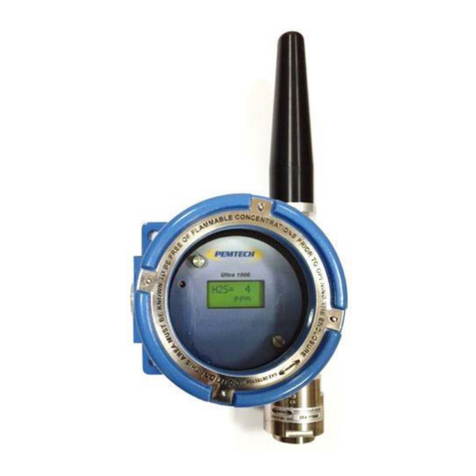
PEMTECH PT2008 Series User manual

NOTICE
PEM-TECH INCORPORATED SHALL NOT BE LIABLE FOR TECHNICAL OR EDITORIAL ERRORS OR
OMISSIONS MADE HEREIN, NOR FOR INCIDENTAL OR CONSEQUENTIAL DAMAGES RESULTING
FROM THE FURNISHING, PERFORMANCE, OR USE OF THIS MATERIAL.
LIMITED WARRANTY
Pem-Tech, Incorporated warrants all the equipment to be free from defects in workmanship and material.
The products will operate in conformance with the published specifications when subjected to intended
and proper usage for the period of one (1) year from the date of shipment.
The warranty provides only the benefits specified and does not cover defects which result from acts
beyond the control of PEM-TECH including, but not limited to: damage by accident, negligence, tampering,
or failure to operate in accordance with the procedures outlined in the Operations Manual. PEM-TECH’s
liability under no circumstances will exceed replacement of the unit claimed to be defective.
Tampering with the equipment and altering it for uses other than the intended use or replacement of parts
not supplied by the company, shall immediately void and cancel all the warranties with respect to the
affected products.
The warranties specified herein are in lieu of any and all other warranties, express or implied. In no event,
whether as a result of breach of warranty or alleged negligence, shall PEM-TECH be liable for special or
consequential damages, including, but not limited to, loss of profits or revenue, loss of equipment or down
time costs.
Wireless Gas Detection Page 2

TABLE OF CONTENTS
1.0 Step by step installation guide 4
Enclosure mounting and dimensions 5
Power and Alarm Connection to PT2008 6
1.1 Overview 7
1.2 Data Display 8
1.3 Front Panel 8
1.3.1 Keypad Switches 8
1.4 Specifications 9
2.0 Installation and Startup 10
2.1 Connection Board assembly 10
2.2 AC Power Input 10
2.3 Alarm Wiring Diagram 10
2.4 Wiring to Alarm Station 11
3.0 Startup 15
3.1 Apply Power 15
3.2 Normal Operation and Alarms 15
3.2.1 Normal Operation 15
3.2.2 Alarms 16
3.2.3 Alarm Reset 16
3.2.4 Alarm Bypass & Acknowledge 16
4.0 Edit System Configurations 17
4.1. Set Alarm Levels 18
4.2. Alarm Relay Types 19
4.3. Enable / Disable Channel 20
4.4 Sensor Location Tags 21
4.4.1 User programmable sensor Tags 21
4.4.2 Setting MS-Windows Hyper Terminal 23
4.5 Network / Zone ID 24
5.0 Communication to PLC 25
MODBUS Registers and Communication 25
MODBUS Register List / Map 27
6.0 Spare Parts List 39
Wireless Gas Detection Page 3

1.0 Step by Step Installation Guide
1. Install PT2008 Monitor to a wall or panel using 4 of the mounting bracket
provided. See figure 1 for mounting holes and enclosure dimensions.
2. Install the Dipole Antenna on top of the enclosure. If external high gain antenna is
installed then connect using coax cable with surge arrestor.
3. Run AC or DC power cable thru the right cable gland and connect to the proper
power input terminal.
4. To connect warning alarm devices, please refer to section on programming alarms
and wiring diagram.
5. At this time the DC power can be applied to the monitor. However, no sensor
reading will be shown. Each channel will show a line “-------------“ in-place of the
gas readings since sensors have not yet been installed and powered up.
Important
Antenna installed must be in line of sight with all the Ultra 1000 Sensors
installed in the facility.
Reminder
Each sensor has been assigned a unique Sensor ID/Address. This address or ID
is indicated via a label on top of the junction box. However, the user may
change this address if needed. The address is also displayed on the LCD
whenever the sensor is powered up. The channel number on the wireless
controller corresponds to the sensor unit address. For example, gas reading for
sensor with Address 1 will be displayed on channel 1, similarly Address 2 will
be displayed as channel 2 and so on.
Wireless Gas Detection Page 4

Figure 1. Fiberglass enclosure, dimensional overview
Wireless Gas Detection Page 5

Figure 2. Connection & Terminal layout inside PT2008 Controller
HINGED DOOR WITH CLEAR VIEWING WINDOW - NOT SHOWN
N L
RELAY-1RELAY-2
T+
T-
RS232
RELAY-3
RELAY-5
COM
NC
RELAY-6
NO
COM
NC
NO
RELAY-4
DC IN
+V
FAULT
GND
COM
NC
NO
Wireless Gas Detection Page 6

1.1 OVERVIEW
Model PT2008 series “Wireless” monitor & controller is designed to monitor and display
data from remote mounted Ultra 1000 Series (wireless) sensors (toxic and Combustibles).
Controller can communicate with up to 24 detectors on the wireless network. The
controller features a large LCD display, 6 fully programmable alarm relay contacts, and a
communication or sensor fault relay. Also on the front panel are LEDs for visual alarm
indicators. On board an RS232 port to program the sensor location tags (optional) and an
RS485 port to send data to PLC or DCS using MODBUS® RTU Communication protocol.
Figure 3. Model PT2008 Controller, Front view
MULTICHANNEL CONTROLLER
MODEL PT2008
ACK.RESET PRGM. ENTER
WARN
ALARM
FAIL
HINGED DOOR WITH CLEAR VIEWING WINDOW - NOT SHOWN
Wireless Gas Detection Page 7

1.2 DATA DISPLAY
PT2008 Controller displays sensor location tags ( or default channel numbers) and the
sensor readings. For controller configured for more than 8 wireless detectors , data is
displayed eight channels at a time. Each screen displays data for 10 seconds and then
display is switched for next 8 channels and so on.
1.3 FRONT PANEL
On the front panel are visual alarm indicators and keypad switches to program controller
configuration. Also, the RESET and ACK key switches are used to Reset and
acknowledge any active alarms, respectively.
1.3.1 KEYPAD SWITCHES
RESET: When pressed in normal mode it will Reset any currently active alarms.
ACK: Pressing the key will bypass or acknowledge active alarms for 30 minutes. After
30 minutes if any sensor is still in alarm state the alarm relays will be activated
again.
PRGRM: Press this key to enter into controller configuration mode.
ENTER, UP & DOWN: These keys are used while editing controller configuration.
Wireless Gas Detection Page 8

1.4 SPECIFICATIONS
Radio Module:
Power Input: 120/220 VAC or 24 VDC
Enclosure: Nema 4X Wall mount fiberglass
Weight: 12 Lbs
Dimension: 19”H x 12”W x 8.5”D
Relays: 7 each Form “C” type fully programmable
Relays rated 5A @ 30VDC or 240VAC
Temperature -25 °C to 60 °C (for LCD)
Range -40 °C to 80 °C (for Electronics and Radio Module)
Display: 240 x 128 Graphic display for gas reading and system configuration
Visual Indicators: LED display for active Low and High alarms and sensor
malfunction
900 MHz 2.4 GHz
Sensitivity -110 dBm -105 dBm
Spread Spectrum
FHSS (frequency Hopping Spread
spectrum
Frequency Hopping, wide band
modulator
Data Encryption 256-Bit AES Encryption
Certification FCC Part 15.247
4214A 1208 Canada
FCC Part 15.247 USA
4214A 1208 Canada
ETSI Europe
Range
Outdoor Line of Sight
Up to 5 miles (8 Km)
With Dipole Antenna
Up to 3 miles (5 Km)
With Dipole Antenna
Wireless Gas Detection Page 9

2.0 INSTALLATION AND START UP
PT2008 series is a wall mount controller. The enclosure is rated Nema 4x weatherproof
and can be mounted outdoors. Refer to figure 1 for overall enclosure dimension and
mounting holes. The mounting feet for the fiberglass enclosure are provided separately.
The monitor should be installed approximately 5 feet above ground. Extreme temperature
condition must be avoided. Avoid installing the unit with the front facing direct sunlight,
and an overhead weather deflecting shield is highly recommended. Conduit entries or
cable glands must be installed at the bottom of the enclosure by the user.
2.1 CONNECTION BOARD ASSEMBLY
To access the connection board loosen the 2 panel screws on right side of the front panel.
This will allow the hinged front panel to swing out. The coax antenna cable and power
and alarm cables must be brought in through the cable glands on the bottom of the
enclosure.
2.2 AC POWER INPUT
Din terminal block are provided for AC power. Refer to figure 2 for the power and alarm
connections.
2.3 ALARM WIRING DIAGRAM
Figure 5 is a typical wiring diagram for connecting alarm devices to relay contacts. The
terminals as shown in figure 5 are pre-wired at the factory. The power to the audio/visual
devices would be the same as the input power to the controller. Refer to figure 5A if the
power to the alarm devices is different than the power to controller.
Note that the relay contacts are form “C” type contacts. Refer to section on monitor
configuration for setting the alarm levels.
Wireless Gas Detection Page 10

2.4 WIRING TO ALARM STATION (Typical for Toxic and Combustible)
Figure 4 shows a sample wiring diagram to connect PT2008 alarm relays to an Alarm
Station. The typical alarm station consists of 2 distinct color strobe light and a buzzer or
siren. The color of strobe light visually distinguishes between the low toxic and
combustible gas alarm. The buzzer or horn is for high alarm for both toxic and
combustible. On PT2008 connection board three relays are configured in order to have
distinct low alarm for toxic and LEL combustible and a common high alarm (siren) for
both toxic and combustible. Alarm relay 1 is wired for Low toxic gas alarm, alarm relay 2
for low combustible alarm and alarm relay 3 for common high alarm. Assume the toxic
and LEL alarm levels are as listed in table below
Sample alarm levels / set-points
Sensor
Type
Low Alarm
High Alarm
Toxic (H2S) 10 15
LEL 20 40
To achieve this alarm relays on the gas monitor must be configured as follows.
Given above alarm level and relay configuration and wiring to alarm station as shown in
figure 5 the audio and visual alarm devices are activated as outlined in the table below.
H2S Alarms
Alarm
Level
Relay #
Low Alarm
10
1
High Alarm
15
3
LEL Alarms
Alarm
Level
Relay #
Low Alarm
20
2
High Alarm
40
3
Wireless Gas Detection Page 11

Sensor Gas Reading Relay #
Activated
Strobe / Horn
Toxic
(H2S, CO, NO,
NO2, SO2,
Etc. )
Greater than or Equal to 10
But
Less than 15
1
Amber Strobe
Greater than or equal to 15 1 & 3 Amber Strobe
& Horn
Sensor Gas Reading
Relay #
Activated Strobe / Horn
LEL
Combustible
Greater than or Equal to 20
But
Less than 40
2
Red Strobe
Greater than or equal to 40 2 & 3 Red Strobe
& Horn
Wireless Gas Detection Page 12

Figure 4. Wiring PT2008 to Alarm Station
CNO
NC
ALARM 4
NC NO
C
ALARM 3
NC NO
C
ALARM 2
NC NO
C
ALARM 1
DC IN
N
NL
BREAKER
++ - -
L
LOW Toxic
Low LEL
High Tox/LEL
RETURN
AC - DC
POWER SUPPLY
CNO
NC
ALARM 6
NC NO
C
ALARM 5
PT2008 Connection Board
Partly show for clarity
Amber
Strobe Red
Strobe
Horn
Audio/Visual Alarm Devices
Amber = Low Toxic Alarm
Red = Low LEL Alarm
Horn = Common High Alarm
(AC Powered)
Supply
Return
Supply
Supply
Return
Return
Wireless Gas Detection Page 13

Wiring Alarm Station using external Power
Figure 4A. Wiring PT2008 to Alarm Station
Wireless Gas Detection Page 14

3.0 STARTUP
3.1 Apply Power
Apply power to the monitor and verify following conditions.
1. The LCD should display startup messages for a few seconds, after which it initializes
the system hardware. Next, it will get the system configuration and alarm set points
from the non-volatile memory.
2. Monitor will display the channel numbers or the channel configuration tags if
previously programmed by the user.
3. The Monitor starts establishing communication with all the sensors on the network and
waits for their data. Each sensor transmits the block of data that includes sensor gas
reading, sensor type and battery voltage.
4. Once the data has been received by the monitor the gas reading and the sensor type
(H2S or LEL) is displayed. Otherwise dashes “-------“ are displayed to indicate no data
received from the sensor.
3.2 NORMAL OPERATION AND ALARMS
3.2.1 Normal Operation
During normal operation the monitor will display the channel number or sensor location
tags with current sensor readings. The channel number corresponds to the Address
number assigned to each Ultra1000 sensors. These addresses must be distinct and
sequential. The controller monitors the data sent by each Ultra1000 sensors on the
network.
3.2.2 Alarms
PT2008 monitor is equipped with four (4) alarm relay contacts. The monitor activates the
alarm relays when any of the sensors exceeds the programmed alarm set point. Also, the
LEDs on the front panel will also light up for visual alarm indication.
Standard alarm set points are programmed at the factory before shipment. The user must
verify the alarm set points and make changes if desired. Refer to section on Programming
Alarm Set points.
Wireless Gas Detection Page 15

3.2.3 Alarm Reset
Once the gas concentration has dropped below the alarm setpoint the relay will deactivate
itself. However, this will occur only if the relay is configured as non-latching (NL). If the
relay is configured latching then it must be deactivated manually. To deactivate the
latching alarm simply press and hold RESET switch on the front panel for few seconds.
The monitor will deactivate the relays and visual LED indicators and will display
***** RESET **** message on the LCD for few seconds.
Note: If the gas concentration continues to be higher than the programmed alarm set point the
alarm will be activated again.
3.2.4 Alarm Bypass or Acknowledge
In the Alarm Acknowledge mode the monitor will not activate the alarm relays if any of
the sensor reading exceeds the programmed alarm level. Press and hold the ACK key
until the Acknowledge message is displayed on the LCD. The displayed message will
indicate the alarm bypass time. This bypass time period is programmed at the factory.
Once the Alarm Bypass time has expired the relays will be activated if the concentration
on the sensor exceeds the programmed alarm level. To terminate the alarm bypass mode
simply press the RESET switch until the monitor displays the RESET message on the LCD.
Wireless Gas Detection Page 16

4.0 Edit System Configuration
To modify system configuration or parameters press and hold the “PGRM” key and the
following configuration menu is displayed. Use the ▲ and ▼ keys to move the arrow to
select the option and press ENTER key.
4.1 Modify Alarm levels and Relays
To modify Alarm levels and set relays select the first option from the Edit Configuration
menu. Following window is displayed
Using the Up and Down arrow key on the front panel keypad move the Pointer on the
LCD to the desired selection and press ENTER to select. Once the target gas type detector
is selected the following alarm level setup screen will be displayed
Edit Configuration
. Set Alarm Levels
Alarm Relay Types
Channel Enable / Disable
Sensor Location Tags
Network / Zone ID
Exit
*** Select to Edit Alarms ****
H2S H2
LEL NO2
CO NH3
SO2 CO2
Oxy Exit
Wireless Gas Detection Page 17

To change the alarm level set the arrow to point to data item to change by pressing the
ENTER key. To change the value press ▲ and ▼ key. Press ENTER key to accept the
data value entered and jump to next level.
Similarly modify the designated Relay for the alarm. Press RESET when alarm levels set
to return the previous Gas Type selection. A message will be displayed “Saving Data” for
few seconds and the system will return to previous menu selection screen.
When all the alarm levels are set for all type of gas detectors on the network, select EXIT or
press the RESET key to return to main Edit Configuration menu.
To change the LEL Alarm levels simply select LEL Alarms for the selection list and follow
the same procedure as discussed above
*** Edit H2S Alarms ***
Level Relay
AL.1 10 1
AL.2 15 3
AL.3 20 5
AL.4 0 0
AL.5 0 0
AL.6 0 0
*** Edit LEL Alarms ***
Level Relay
AL.1 20 2
AL.2 40 3
AL.3 50 6
AL.4 0 0
AL.5 0 0
AL.6 0 0
*** Select to Edit Alarms ****
H2S H2
LEL NO2
CO NH3
SO2 CO2
Oxy Exit
*** Select to Edit Alarms ****
H2S H2
LEL NO2
CO NH3
SO2 CO2
Oxy Exit
In the above example, for all H2S detectors Low, High and Hi-Hi alarms are set at 10, 15 & 20
ppm respectively. Also Relay 1 is designated for Alarm 1 (low), Relay 3 and Relay 5 are
designated for Alarm 2 (High) and Alarm 3 (Hi-Hi) respectively.
Wireless Gas Detection Page 18

4.2 Alarm Relay Type
This option allows the user to select the alarm relays to be Latching or Non-Latching type. Also if
the relays to function as Normally Energized or De-Energized mode.
Select Relay Type from the edit configuration option list and the following screen is displayed.
Press ENTER key to move the arrow pointer to the data value that needs to be modified. The
press ▲and ▼keys to toggle the value between Latching and Non-Latching or Norm-Energ(ised)
or De-Energ(ised) relay status.
FLT is the sensor Fault or Comm Error Relay
**** Relay Type ***
R #1 Non-Latch De-Energ
R #2 Non-Latch De-Energ
R #3 Non-Latch De-Energ
R #4 Non-Latch De-Energ
R #5 Latching De-Energ
R #6 Latching De-Energ
FLT Non-Latch De-Energ
Latching alarm relays require manual RESET, where as non-latching alarms are
auto reset, that is they are deactivated once the gas concentration falls below the
programmed level or set point.
Normally Energized relays are typically used for Fail Safe operation. In normal
operation and below alarm levels the relays are active and energized. The relays
are De-Energized when the gas Concentration reaches to or above the alarm level
or set point. Normally Energized relay configuration is selected when dry contacts
are used to power the solenoid valves in normal operation and to cut off power to
the solenoid once an alarm condition occurs.
Wireless Gas Detection Page 19

4.3 Channel Enable / Disable
Select this option to Enable / Disable detectors. The controller can interface up to 24
detectors. However if fewer than 24 detectors are on the network then disable the
detectors in order to avoid the Comm Fail Error message.
Following screen is displayed when option is selected. Eight (8) channels are displayed at
a time on the screen. Use ▲ and ▼ key and the keypad to set the pointer to the channel
number and press Enter to toggle between “Enable” and “Disable” option.
The above configuration illustrates that channel / detector with address 13 thru 16 have
been disabled, thus making the unit as a 12 channel controller. PT2008 will only display
data from 12 detectors on the network. If any additional detectors are installed then
simply enable the channel.
CH 01
* Enable *
CH 02 * Enable *
CH 03 * Enable *
CH 04 * Enable *
CH 05 * Enable *
CH 06 * Enable *
CH 07 * Enable *
CH 08 * Enable *
CH 09 * Enable *
CH 10 * Enable *
CH 11 * Enable *
CH 12 * Enable *
CH 13 * Disable *
CH 14 * Disable *
CH 15 * Disable *
CH 16 * Disable *
Wireless Gas Detection Page 20
Other manuals for PT2008 Series
2
Table of contents
Other PEMTECH Gas Detector manuals
Popular Gas Detector manuals by other brands

MSA
MSA ULTIMA X5000 operating manual

Riken Keiki
Riken Keiki SD-1D operating manual

Riken Keiki
Riken Keiki GD-F3A-1 Operation and maintenance manual

Crowcon
Crowcon IRmax Installation, operating and maintenance instructions

CCI Controls
CCI Controls 7719 instructions

Sensitron
Sensitron SMART S Installation and user manual