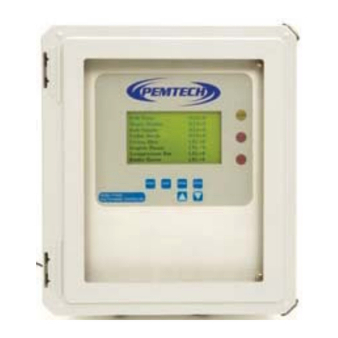
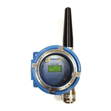
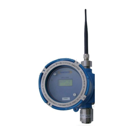
PEMTECH PT495 Series User manual

PT495 Series
(Ultra1000 )
Stand Alone Addressable
Gas Detector
Toxic, Oxygen Deficiency, & Combustible (HC)
Revision 5.11
October 2020
Operator’s
Manual
Pem-Tech, Inc.
Houston, Texas
U.S.A
www.pem-tech.com
Gas Detection Technology

PT495 Series Detector (Ultra1000) Rev 5.11
2
Table of Contents
Notice and limited Warranty 3
Specifications 4
Overview 5
Table 1. List of target gases 6
Transmitter Board assembly 7
Connection Board assembly 7
Accessories 8
Installation 10
Transmitter Wiring 11
Wiring Diagrams
DC Power and 4-20mA Signal Output 13
Low and High Alarms Connections 14
Start Up 15
Normal Operation 15
Gas Reading Display 15
Signal Output 4-20mA 15
Calibration 18
Sensor calibration 18
Response check / Bump Test 22
Adjusting or Re-setting Zero Only 22
Calibration errors and remedies 23
Calibration Flow Chart 24
Edit Configuration (alarms and Unit Address) 25
Configuration menu 26
Set Detector Address 27
Set Alarm Levels 28
Alarm Conditions 30
Low Alarm, High Alarm & Fault 30
Resetting Alarms 31
Modbus RTU Communication 32
Communication Parameters 32
MAINTENANCE
Routine maintenance 35
Sensor Inspection, sensitivity and replacement 36
Spare Parts 38
Sub assemblies and calibration accessories

PT495 Series Detector (Ultra1000) Rev 5.11
3
IMPORTANT
Be sure to read and understand this instruction manual before installing,
operating or servicing the gas detection equipment.
WARNING
•Do not open the sensor enclosure with power applied unless it is verified that
no combustible gases or vapors are present. Calibration or maintenance
should not be performed if there is any indication of the presence of
combustible gas near the sensor.
•If anytime an intrusive sensor calibration procedure has to be performed then
de-classify the area before opening the sensor junction box.
•The sintered flame arrestor on the stainless steel sensor head is an integral
part of the complete sensor assembly. Do not operate the gas sensor with the
flame arrestor removed or damaged.
•The detector muse be earthed / grounded for the electrical safety. A safety
lug on the right side of the enclosure is provided for grounding.
CAUTION
•If needed the enclosure threads may be coated with silicone free grease.
Silicone based lubricants must never be used.
•Follow the wiring instruction for proper and safe operation under normal
conditions. Be sure that all wiring complies with NEC and all local ordinances.

PT495 Series Detector (Ultra1000) Rev 5.11
4
SPECIFICATIONS
Sensor Type:
Continuous diffusion / adsorption
Combustibles (HC): Infrared & Catalytic Bead
Carbon Dioxide: Infrared
Toxic and Oxygen: Electrochemical
Typical Measuring Ranges
See Table 1 for target gases and range
Repeatability
±2 % Full scale
Electrical Classification
Explosion Proof
ATEX: II 2 G EX d IIC T6 (Tamb = -34°C to +100°C)
CSA: Class I, Div 1 & 2, Groups B,C& D
C22.2 No 30-M1985 &
C22.2 No 142-M1987
Ingress Protection
NEMA 4X, IP66
Approvals
CSA , ATEX/IECEx
Typical Response Time &
Operating Temperature Range
See Table 1 for details
Operating Humidity
15% to 90% RH, non-condensing (Toxics)
0 – 95%RH, non-condensing ( HC, CO2)
Storage Temperature
-40°F to +167°F (-40°C to +75°C)
Mechanical Specifications
Height: 7.4inches (188 mm)
Width: 6.2 inches (159 mm)
Depth 4.9 inches (125 mm)
Display
LC Display with backlight
Status Indicators
LC display for gas concentration,
Alarm status, calibration mode and fault status.
Input Power
14-28 VDC. 24 VDC nominal
Power Consumption
55 mA @ 24 VDC typical
Alarm Relays
3 each Fully programmable for Low & High alarm levels and
sensor Fault. Also programmable as Latching or Non-
Latching.
Relay Ratings
SPDT Form “C” type Relay contacts
1Amps @ 250 VAC or 30 VDC
Analog Output
Linear 4-20mA ; 0 -100% Full Scale (300 Ohms max. load)
2.0 mA - Calibration mode
< 1.0 mA - Sensor malfunction
Serial Output
RS-485 (9600 Baud Rate) Modbus™ RTU protocol
Cable Requirement
3 wire shielded cable for Power and Analog output
Terminal connectors 12 AWG Max
Input / Output Protection
Transient over voltage suppressor,
Reverse polarity protection
EMI/RFI Immunity
Cable Entry Hub
¾” NPT Female
Adapter available for ½” NPT / M20

PT495 Series Detector (Ultra1000) Rev 5.11
5
Overview
PT495 series single point fixed detector and transmitter for the detection of toxic and
flammable gases in ambient air. Detector is designed and built suitable to be used in
hazardous area. The detector is approved for use in Class I Division 1 & 2 classified areas
(North America) or Zone 1 and 2 (International).
The transmitter features a display and three programmable relays for controlling external
devices like alarms, sirens, switches and solenoid valves. The transmitter provides
an industry standard 3-wire, 4-20mA (source) output for connection to a gas detection
system or a PLC.
Table I lists the target gases and the detection ranges. The unit displays the gas concentration
and transmits a linear 4-20mA analog output signal proportional to the gas concentration
displayed. The unit is also equipped with 3 forms “C” type alarm relay contacts. Two (2)
alarm relays are fully programmable as Low and High alarms and 1 for sensor Fault or
Malfunction.
The detector also features a non-intrusive calibration. Calibration is performed by activating an
internal magnetic switch. Calibration is an easy automated procedure that does not require
any manual adjustment to the unit. All calibration and alarm configuration data is retained in a
non-volatile memory.
Field Cable Entry (x2)
¾” NPT
One Entry with Ex Plug
Stainless Steel (316)
Sensor Head Assembly
Transmitter assembly
Mounting Holes (X2)
Earth Ground Lug
Figure
1. PT495 Series Detector

Toxic Gases
Target Gas
Max Range
Sensor
Type
Res.
Calib Gas
Range
(user
Selectable)
Default
Calib Gas
Used
Response
time (T50)
seconds
Recovery
Time (T59)
seconds
XXX
Operating Temperature
Default alarm Levels /
Set Points
Min
Max
Alarm 1
Alarm 2
Ammonia
(NH3)
50 ppm
Electrochemical
Sensors
0.1 ppm 5-35 ppm 25 ppm < 60 ~ 90
-4°C / 24°F 50°C / 122°F 5 ppm 10 ppm
Carbon Monoxide
(CO) 100 ppm 1 ppm 20-50 ppm 50 ppm < 25 ~45
-20°C / -4°F 55°C / 131°F 20 ppm 50 ppm
Carbon Monoxide
(CO) 300 ppm 5 ppm 50-150 ppm 50 ppm < 25 ~45
-20°C / -4°F 55°C / 131°F 100 ppm 150 ppm
Chlorine
(CL2)
10 ppm 0.1 ppm 2-10 ppm 5 ppm < 60 ~50
-20°C / -4°F 55°C / 131°F 2 ppm 5 ppm
Hydrogen 1,000 ppm 10 ppm 100-500 ppm 500 ppm < 90 ~40
-20°C / -4°F 55°C / 131°F 200 ppm 500 ppm
Hydrogen Chloride
HCL
50 ppm 1 ppm 10 -50 ppm 25 ppm < 45 ~120
-20°C / -4°F 55°C / 131°F 200 ppm 500 ppm
Hydrogen Sulfide
(H2S) 25 ppm 0.1 ppm 5-25 ppm 20 ppm < 20 < 50
-40°C / -40°F 65°C / 149°F
(intermittent) 10.0 ppm 15.0 ppm
Hydrogen Sulfide
(H2S) 100 ppm 1 ppm 20-50 ppm 50 ppm < 20 < 50
-40°C / -40°F 65°C / 149°F
(intermittent) 10 ppm 15 ppm
Hydrogen Sulfide
(H2S) 500 ppm 1 ppm 50-150 ppm 50 ppm < 20 < 50
-40°C / -40°F 65°C / 149°F
(intermittent) 50 ppm 100 ppm
Mercaptan 100 ppm 1 ppm 20-50 ppm 50 ppm < 20 < 50
-20°C / -4°F 55°C / 131°F 10 ppm 15 ppm
Nitrogen Dioxide 50 ppm 1 ppm 10-50 ppm 10 ppm < 50 ~ 75
-20°C / -4°F 55°C / 131°F 10 ppm 15 ppm
Nitric Oxide
(NO)
100 ppm 1 ppm 20-50 ppm 25 ppm < 45 ~ 60
-20°C / -4°F 55°C / 131°F 20 ppm 50 ppm
Oxygen
(O2)
25 %V/V 0.1 %
Calibrated in fresh air.
Purged with Pure Nitrogen
< 15
from 20.9% to 0
~ 40
-20°C / -4°F 55°C / 131°F
19.5%V/V
(falling)
23.5%V/V
Sulfur Dioxide
(SO2)
100 ppm 1 ppm 20-50 ppm 25 ppm
< 35
~50
-20°C / -4°F 65°C / 149°F
(intermittent)
5 ppm 10 ppm
Carbon Dioxide
(CO2)
5 %
Infrared
Sensors
0.1 % 2 – 5 % 2.5 ppm < 15 ~ 40
-40°C / -40°F 75°C / 167°F 2 % 3.5 %
Carbon Dioxide
(CO2) 100% 1 % 10 – 100 % 50 ppm < 15 ~ 40
-40°C / -40°F 75°C / 167°F 20 % 50 %
Combustible Hydrocarbons
Target Gas
Max Range
Sensor Type
Res.
Calib Gas
Used
Response Time
(T90) seconds
Recovery Time
(T50) seconds
Accuracy
%
Operating Temperature
Default alarm Levels /
Set Points
Min
Max
Alarm 1
Alarm 2
Flammable
(Hydrocarbons)
100 % LEL
(5% Methane in Air) Catalytic
Bead 1 % 50 % LEL < 45 < 20 ±2 -40°C / -40°F 75°C / 167°F 20 % 40 %
Hydrocarbons
(Methane /
Propane)
100 % LEL Infrared 1 %
50 % LEL
(methane or
propane)
< 45 < 20 ±2 -40°C / -40°F 75°C / 167°F 20 % 40 %
Table 1. Reference Table for Target Gas Range and default parameters
Rev 2: 3/5/19

Transmitter Board
The transmitter board assembly consists of the signal conditioning circuit,
microprocessor, LC display and 4-20 mA output circuit. The transmitter board
assembly is connected to the connection board via ribbon cable and secured
onto the stand-off via two thumb screws. To remove the transmitter board
simply move the thumb screws counter-clockwise and slowly pull the transmitter
board away. Unplug the ribbon cable to completely remove the transmitter
board from sensor unit.
Note: Do not use force to tighten the thumb screws when installing the
transmitter board back on the connection / termination board.
Connection Board
The termination or connection board consists of relays and DC-DC power
converters for the transmitter board and the sensor. The power converters are
protected against reverse polarity.
A 3 pin terminal is provided for user interface to the monitoring device for power
input and 4-20ma output. Three (3) Pin terminal blocks are also used for alarm
connections. Each pin on alarm terminal block is labeled as C (common), NC
(normally closed) and NO (normally open). See Figure 3.
The 4 pin terminal at the bottom of the board is labeled SENSOR. Wires from the
sensor head assembly are connected to this terminal.
Each terminal contact is labeled as R(ed), G(reen), W(hite), B(lack). the toxic
sensors are 4 wires while Hydrocarbons LEL (Catalytic bead) and all infrared
sensors are 3 wires.
See figure 2 for drawing of Transmitter board and connection board assembly.

PT495 Series Detector (Ultra1000) Rev 5.11
8
Accessories
Range of accessories is available for the use of detector in various applications.
Rain / Dust guard: To protect the sensor head assembly against the
accumulation of dust / sand on the sintered disk of the head assembly.
Also to protect against water splashes.
Duct Mount Kit: This is an optional kit designed to monitor the gas
vapors in Heating, ventilation and air conditioning duct (HVAC).
Figure
2. Transmitter and connection board assembly

PT495 Series Detector (Ultra1000) Rev 5.11
9
Flow Thru Adapter. A machined aluminum assembly with either 1/8”
Hose barb fittings or ¼” Compression fittings. This adapter is designed to
use in application for continuous flow of gas through the sensor head
assembly.
Calibration Adapter with Tubing: Also a part of calibration
accessories. Used along with the flow regulator to flow the calibration gas
to the sensor. Attached is 6 feet ¼” nylon tubing.
Magnetic Wand: A tool used to initiate the internal magnet sensitive
switches for alarm configuration and to initiate sensor calibration.
Pipe Mount Assembly: Includes hex bolts and stainless steel bracket
to mount the sensor to up to a 2” pipe.

PT495 Series Detector (Ultra1000) Rev 5.11
10
Installation
Refer to figure 3 for PT495 Detector explosion proof enclosure for mounting and
conduit connection.
The unit has 2 integral mounting holes. The unit can be mountd directly to a
surfce or to a horizontal or vertical pipe structure. An optional pipe mount
bracket can be used to mount the unit to a pipe up to 2” in diameter or cross
section. Two (2) Cable entries are provided on each side of the enclosure.
Either side can be used for the cable entry. The other side must be plugged with
the one supplied with the unit. A CSA or ATEX approved plug must always be
used.
5.50"
7.4"
4.9"
(125mm) (139.7mm)
(188mm)
Ø 0.3" (7.6 mm)
2 Places
3
4" NPT Female
Both Sides
Cable Entry
Figure
3. Sensor Dimensions

PT495 Series Detector (Ultra1000) Rev 5.11
11
Transmitter Wiring
Follow steps below for installation.
1. Remove the enclosure cover and un-plug the transmitter board by simply
moving the thumb screws in counter-clockwise direction until they have
loosened up. Slowly pull the transmitter board and detach the ribbon cable.
Do not completely un-screw or remove the thumb screws from the transmitter
board.
2. Using a 3 conductor cable connect the termination board with the monitor or
controller as shown in figure 4. A shielded instrumentation cable must be
used to connect the detector to the controller for power and signal output.
Refer to the cable size chart at the end of this section for proper cable.
3. If the serial communication port is to be used on the transmitter then connect
RS485 terminal to the Communication Port of the PLC or the Control monitor
using data quality type Shielded cable. Two (2) core cable is used for Half-
Duplex RS485 data communication.
4. For Audio / Visual alarm connection or Alarm Relay Dry Contact, refer to
figure 5 for wiring diagram. Be sure that the power rating of the alarm device
does exceed the Ampere rating of the alarm relay contacts. See relay ratings
in the specification section of the manual.
5. Reconnect the transmitter board with the connection board with the 10 pin
ribbon cable. Mount the transmitter board on two 2 stand-offs using thumb
screws on the board. Note: Do not apply excessive force to tighten the
screws.
6. Place the cover back on the enclosure.
Caution: Cable Shield wire should be grounded at the controller or PLC
side not inside the detector enclosure.

PT495 Series Detector (Ultra1000) Rev 5.11
12
Note: Minimum voltage required for proper operation is 16VDC. If necessary verify
the input voltage by using Digital Multi Meter (DMM) at +V and –V terminals on the
connection board.
Reference Wire size Table
Assuming +24VDC or power input from the source, 8 volts of maximum voltage drop at the
detector power terminals, following would be power consumption of the detector
Cable Size
Cable resistance
Ω/km (Ω/1000Ft)
Max Cable Length*
Meters / (feet)
Catalytic Bead
Toxics & Infrared
0.5 mm2(20AWG) 34 (10.4)
425
(1400)
0.82 mm2(18AWG) 21.4 (6.5)
670
(2200)
1.3 mm2(16AWG) 13.4 (4.08)
1030
(3400)
2.0 mm2(14AWG) 8.45(2.57)
1490
(4900)
Data above is for a stranded copper type cable
* The max cable length is estimated based on 24 Volts DC power to the detector and
maximum load of 100 Ωon the controller or signal receiver.
Max resistance per core : R = V/I 8volts / detector consumption (A)
Max Loop resistance for toxic & infrared 67.8 Ω
Catalytic Bead: 29.8 Ω
Sensor Head
Types
Nominal Power
At VDC
With 8 Volts of drop,
V= 16 volts
I = P/V
Combustible
(Catalytic Bead) 4.3 watt 268 mA
All Toxics & Infrareds ~1.9 watt 118 mA
The wire size data below is for reference only. Refer to the manufacturer
specification of the cable that is being used to ensure the maximum cable length
and proper operation of the unit.

PT495 Series Detector (Ultra1000) Rev 5.11
13
Figure
4. Wiring Diagram for Power and 4-20 mA signal connection

PT495 Series Detector (Ultra1000) Rev 5.11
14
Figure
5. Wiring diagram for Alarm Relay Connection

PT495 Series Detector (Ultra1000) Rev 5.11
15
Start Up
After installation apply power to the unit. Upon power up the unit will display
the current Address (or unit id) of the sensor. The address must be unique
when sensor is connected to RS485 MODBUS RTU network. Few seconds later
Low and High alarm levels (also referred to as Alarm 1 and Alarm 2) are
displayed. If different alarm set points are desired then refer to section “Adjust
Alarm Set Points” to modify alarm parameters.
If the transmitter does not start with the sequence as stated above then verify if
the ribbon cable connector is plugged in properly. If necessary unplug the
ribbon cable and plug it back again. The connector is keyed and can be inserted
only one way.
The sensors are calibrated at the factory before they are shipped. However, it is
a good practice to check the accuracy by simply applying the calibration gas after
the warm up time and check to see if the concentration displayed matches with
concentration of the test gas within tolerance. If calibration is required then
follow the steps in the Calibration procedure. If the unit is powered up for the
first time then allow at least 15 to 20 minutes before attempting calibration or
bump test.

PT495 Series Detector (Ultra1000) Rev 5.11
16
Operation
Normal Operation
The sensor is considered in normal operation after startup procedure is complete
and is not indicating any alarm or sensor fail (FAULT) condition.
Gas Reading Display
The sensor displays the gas concentration in % volume or ppm (parts per million)
by volume.
Signal Output 4-20mA
The 4-20mA signal output is directly proportional to the detection range of the
sensor. The output signal generated is proportional to the gas concentration
displayed on the transmitter LCD.
Use the formula below to compute the mA output for any given gas
concentration or vice versa.
Formula to convert gas reading to mA:
( 16 x gas_reading ) + 4 = Analog output (mA)
Detection Range
Formula to convert mA to gas reading:
( mA Output - 4 ) x Detection Range = gas_reading
16
(Note: Detection Range is the full scale range of the sensor)

PT495 Series Detector (Ultra1000) Rev 5.11
17
% / ppm
Volume
mA Output
0
4.0
10
5.6
20
7.2
25
8.0
50
12.0
75
16.0
100
20.0
The above table is for the detector with Full scale range of 100 ppm / % (volume)

PT495 Series Detector (Ultra1000) Rev 5.11
18
Calibration
Refer to Table at the end of this section for the recommended calibration gas for
the target sensor. Also see section on Spare Parts for part numbers for other
calibration accessories.
Following items are needed for the sensor calibration:
•Calibration adapter with tubing
•Magnet tool to activate the switch on the transmitter board assembly.
•Calibration gas bottle with flow regulator. The flow of the calibration gas
should be approximately 0.5 to 1 LPM (liters per minute)
See Figure 7 for setup
The sensor can be auto calibrated without removing the enclosure cover and
declassifying the zone. A magnet tool is used to activate the internal switch to
initiate the calibration. Once the calibration is initiated the alarm relays will be
inhibited and the 4-20mA analog signal will be held at approximately 2mA to
avoid any false alarm.
Calib
Mode
Magnetic Wand
Figure
6. Magnetic switch position to activate calibration Mode switch

PT495 Series Detector (Ultra1000) Rev 5.11
19
Follow the steps below to calibrate the sensor.
1. Remove the rain / splash guard if attached.
2. Make sure the detector and ambient air is clear of any target gas vapors.If
the air is contaminated then apply the purging (zero) air to the sensor in order
to remove the toxic vapors from the sensor head assembly. ( If zero air is
applied then do not remove air until after step 5)
3. Place the magnetic tool against the cover at 8 o’clock position to activate the
magnetic switch as shown in figure 7.
4. Place and hold the magnet until display indicates the “Calib Sensor” . Move
the magnet away from the cover.
5. While the Calib Sensor message is being displayed the sensor is making its
initial adjustments. It may take 5 to 10 seconds. (Note: Do not apply
calibration gas yet)
6. Once the initial adjustments have been made, remove the zero air if applied.
The unit will display the default Calibration Gas concentration or the
concentration of the calibration gas used last time. Make sure the Calib-Gas
value displayed on the LCD matches the gas concentration of the cylinder
being used for calibration. Else simply place and hold the magnet to the cover
at 8 o’clock position to change the default Calibration gas concentration.
Hold the magnet at its place on the enclosure cover until the display reads the
desired cal-gas value. Refer to Table 1 for the range of calibration gas
concentration used. The recommended calibration gas concentration is 50%
of the full scale range of the detector. For example, for 100 ppm H2S
Detector, a 50 ppm H2S Calibration Gas is used. The selected calibration gas
value will be stored in a non-volatile memory and remains unchanged until
modified.
*** Note: For Oxygen deficiency pure nitrogen is applied as calib gas
and thus value is not adjustable. Similarly for LEL detectors the Calib-
Gas is fixed at 50% LEL.

PT495 Series Detector (Ultra1000) Rev 5.11
20
7. The microprocessor waits 60 seconds for the user to apply the calibration gas
while flashing the display approximately twice every second. Attach the
calibration adapter to the sensor head assembly and turn the gas on. When
the flow of the gas is detected by the sensor the display flashing rate will slow
down to once every second. If no gas is detected within 60 seconds the
sensor aborts calibration and will display error message “Calibration Time
Out” for few seconds before returning to normal operation..
8. Apply the calibration gas for about 2 minutes.
9. After 2 minutes the sensor will display Adjustng for 5 to 15 seconds while
making adjustments and recording the calibration data into memory. When
completed the display will starts flashing rapidly. At this time remove the
calibration gas and allow the sensor to clear. Do not remove the calibration
gas while the sensor is adjusting. Remove the gas only when the adjustment
is completed and the display is rapidly flashing with calibration gas value.
10. After successful calibration “Calibrat OK” message is displayed for few
seconds on the LCD.
11. While the gas from the sensor head assembly is being cleared the 4-20mA
analog output will be held at 2.0mA and alarm relay will not be activated until
the sensor has cleared. Once cleared the unit will return to its normal
operation. The 2mA level on the analog output line is an indication to any
connected gas monitor that the sensor is in calibration mode thus avoiding
any false alarm.
Also refer to “Sensor calibration Flow Chart” for quick calibration review and
“Calibration Error and remedies”
Table of contents
Other PEMTECH Gas Detector manuals
Popular Gas Detector manuals by other brands

MSA
MSA ULTIMA X5000 operating manual

Riken Keiki
Riken Keiki SD-1D operating manual

Riken Keiki
Riken Keiki GD-F3A-1 Operation and maintenance manual

Crowcon
Crowcon IRmax Installation, operating and maintenance instructions

CCI Controls
CCI Controls 7719 instructions

Sensitron
Sensitron SMART S Installation and user manual