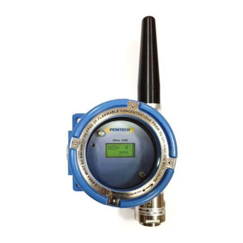
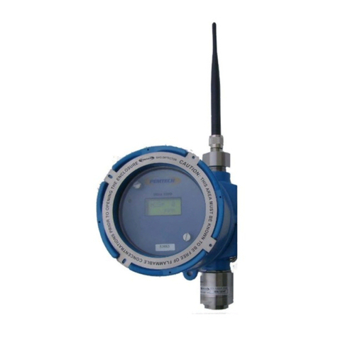
PEMTECH PT2000/H Series User manual

Model PT2000/H Series
Wireless Gas Detection System
Revision 2
January 2014
Manual
Pem-Tech, Inc.
Houston, Texas
U.S.A
www.pem-tech.com
Gas Detection Technology

2
OperatorsManual Model PT2000/H Series GasMonitor Rev 2. January 2014
FOREWARD
This document covers quick setup of PT2000/H Series Wireless Gas
Monitor &Controller and Wireless Gas Detectors. Included are procedures
for setting up the detectors and wiring diagram to connect Audio/Visual
Alarm station to the controller.

3
OperatorsManual Model PT2000/H Series Gas Monitor Rev 2. January 2014
Table of Contents
Section Page #
1.0 Quick Setup Guide and Check List 5
2.0 Introduction 8
3.0 Setting Up PT2000 WirelessController 9
3.1 Installing SIM Cardfor Cell Phone Module 9
3.2 Installing External Panel Mount Antenna for Cell Module 11
3.3 Installing Antenna 11
3.4 Connection & Wiring Diagramfor Audio / Visual Alarms 12
3.5 Main AC Power Connection 14
4.0 System Configurati 15
4.1 15
4.1.1 SiteName 16
4.1.2 Ethernet IP Address 16
4.1.3 Active # of Relay Modules 16
4.1.4 Alarm Bypass Time 16
4.1.5 Wireless Network or Zone ID 17
4.1.6 Call Out /Alarm Text Messaging 17
4.1.7 Enable/DisableWireles 17
4.2 Channel / Sensor C 18
4.3 ConfigureA 19
4.4 ConfigureRela 21
4.5 Modify Callou 22
4.6 Alarm 23
4.7 24
4.8 24
4.9 Display Backlight Timer 25
4.10 25
5.0 Normal Operation 26
5.1 Main Display Screen - Sensor Data 26
5.2 27
5.3 29
5.4 Alarm RESET & Ala 30
5.5 AlarmCallout 31
5.6 RemoteAlarmB 32
6.0 Historical Data Logging 33
6.1 Interval Log 33
6.2 Event & Alarm Log 34

4
OperatorsManual Model PT2000/H Series Gas Monitor Rev 2. January 2014
6.3 Downloading Log Data to USB 34
6.4 Sample DataLog in Excel 35
6.5 View Interval Log Data
6.6 View Historical Event & Alarm Log 38
6.7 Erase Data Logs 39
7.0 Setting Up Wireless Detectors 40
7.1 Installing Detectors on Pole using Brackets 40
7.2 Installing Antenna 41
7.2.1 DipoleAntenna 41
7.2.2 Yagi Directional Antenna for Long distance 42
7.3 Power to the WirelessDetectors 44
45
8.1 Program Detector Address and Zone/Network ID 45
47
49
51
Appendix A
List of Drawings and diagram

5
OperatorsManual Model PT2000/H Series Gas Monitor Rev 2. January 2014
1.0 Quick Setup Guide / Check List
Follow step by step instruction below for quick setup of the system. Details are
outlined in the section number referred in the right column.
Step #
Description
Refer
Section #
1
If the unit is to use Alarm Text messaging function then an active SIM
Card must be installed in order for onboard Cell Module to activate.
See Section on SIMCardInstallation for details.
3.1
2
Install PT2000 Series Wireless Controllerin safeand indoor.
3
Inside the Controller move the AC Circuit Breaker (Next to AC/DC Power
supply) in OFF position (downward). Connect AC Power to the Unit as
per local Electrical codes.
3.5
4
For proper wireless communication antenna must be installed at an
elevated level connected to the controller with the coax cable. Use the
antenna and the coax cable supplied with the controller. Using
antenna and or cable other than the one supplied by Pem-Tech could
result in inefficient data communication between the detectors and the
controller.
3.3
5
If Hardwired Audio/Visual Alarm Station is tobe used then follow the
wiring diagram for the Alarm station referred later in the manual.
If Wireless Remote Alarm RelayModule is used then refer to Wiring
Diagram Drawing # B2013138 in Appendix A
3.4
6
Verify AC Power Connection and then apply AC power to the unit.
Move the Circuit Breaker to UPWARD position to turn the unit ON.
3.5
7
Unit is shipped with default setting for H2S and LELalarmlevels and 12
wireless detectors as Active (for a 24 Channel Unit). The Controller is
ready to receive the data from wireless detectors if installed. However, if
the detectors are not installed then after 2-5 minutes each detector
data block on the display screen will indicate CommFail. Once
detectors are on-line this message will clear andthe sensor reading will
appear in the data block of the main display screen.

6
OperatorsManual Model PT2000/H Series Gas Monitor Rev 2. January 2014
Step #
Description
Refer
Section #
Setting Up Wireless Detectors
8
Install Wireless Detector to apole or any fixed structure using the Pole
Mount bracket if Supplied.
7.1
9
For Short and clear Line of sight distance a dipole antenna can be
simply installed on top of the Detector. Always use the protective
polycarbonate antenna cover to protect the antenna and the connector
against the environment.
For Long distance use the Coax Cable and the Yagi Directional Antenna
supplied.
**Caution: UsetheantennaandcoaxcablesuppliedonlybyPem-Techas
theAntennagainandthecablelosshavebeenfactoredinthe
communicationparametersfortheWirelessRadioModuleinsidethe
detector.
7.2
10
Powering the Wireless Detectors:
If Solar Powered then simply connect the solar Panel power
cable to the receptacle on the left side of the Detector Enclosure
For Battery Powered units.
Remove the glass cover. Unscrew the 2 Thumb screws on
the top panel of the detector to remove the panel
Verify the batteries are installed and secured in the
battery holder.
Re-Connect the Display board with connection board
inside with short ribbon cable. DonotTwistandTurnthe
RibbonCable.
Install the display panel back. Secure using the 2 thumb
screws. Donotuseexcessiveforceorscrewdrivertotighten
thethumbscrews.Simplyhandtightthescrews.
position with a magnet to activatethe internal switch to
turn ON the Unit. The switch is located right underneath
the cover plate above the LCD. If the magnet is weak
due to the enclosure wall thickness it may not be able to
activate the internal switch. Simply remove the cover
half way and then touch the internal wall of the
enclosure body (threaded side) to activate the switch.
7.3

7
OperatorsManual Model PT2000/H Series Gas Monitor Rev 2. January 2014
Step #
Description
Refer
Section #
11
Once the detector has been powered up a proper Unit ID/Address must
be assigned to identify itself to the main wireless controller. All
detectors must have consecutive numeric ID number. For example
with 12 Detectors in use UnitID/Address must be from 1thru 12. Refer
to section on Unit Id for details
8.1
12
Detectors should now be transmitting data to the controller. Unit
Address is synonym to Channel numberin the main controller.
13
Install all the Wireless detectors. Besurethateachdetectormusthave
adistinctUnitID/Address. Notwodetectorsshouldhavethesame
UnitAddress.
Leave the Zone ID to 0 at this point time. Refer to section on Address
and Zone ID for further details.

8
OperatorsManual Model PT2000/H Series Gas Monitor Rev 2. January 2014
2.0 Introduction
Model PT2000/H is a PLC Based Gas Monitor & Controller designed tointerface to wide
range of Wireless Toxic and Combustible gas detectors. This unit comes in standard
with GPRS Cell Modem for Alarm Text messaging and internal flash memory for
historical data logging. Also onboard are 4 programmable Relay Contacts that can be
interfaced with Audio/Visual Alarm Devices. Additional Relay Modules can be added if
needed.

9
OperatorsManual Model PT2000/H Series Gas Monitor Rev 2. January 2014
3.0 Setting Up PT2000 Controller
3.1Installing SIM Card for GPRS Cell Phone Module
The unit is shipped from the factory without any SIM card. User must install a valid SIM
card acquired from the local cell phone provider. This procedure is performed only
once upon receiving the brand new unit from the Pem-Tech. SIM Card does not need
to be removed from the controller when the system is not in use for extended period
of time.
Before installing the SIM card be sure that the power is completely removed. Also
extra care need to be taken when opening the back cover of the screen display. Avoid
opening the unit in dusty environment and avoid any static damage to the unit.
Following is the step by step procedure to install the SIM Card.
Remove Power from the unit if currently ON
Disconnect the power, USB Extension
Cable and RJ45 cable from the bottom of
the PLC Display screen. Remove the
screws (5 each) in order to remove the
back cover.
Lift to cover gently to avoid any damage
to the flex cables inside the unit.
Unplug power and Data Cables
Remove Screws to loosen the cover

10
OperatorsManual Model PT2000/H Series Gas Monitor Rev 2. January 2014
GPRS Cell Module is locatedon the right
side of the Display. Slide the SIM card
under the small metal frame. Note that
the angled-notch on the SIMcard must
be facing down as shown in picture.
Push the SIM card gently all the way
under the metal bracket to secure. At
any time do not apply excessive force.
Now replace the back cover with care. Make sure the ribbon cable on top of the
display does not get pinched between the cover and the frame.
Secure the back cover with the mounting screws.
Reinstall power plugs, RJ45 data cable and any other cables/wires as were
originally installed.

11
OperatorsManual Model PT2000/H Series Gas Monitor Rev 2. January 2014
3.2 Installing External Cell Modem Antenna
A small panel mount antenna (provided with the Controller) is to be installed on top of
the unit Enclosure. Run the antenna cable thru the mounting hole on top of the
enclosure. Connect the antenna cable onto the SMA Male connector behind the touch
screen display. Secure the antenna on the enclosure. See the drawing below for
mounting. Also Refer Figure 2 to connect the SMA connector of the Antenna cable to
the back of the PLC Control Display.
3.3 Installing Antenna for Wireless Communication
An Omni Directional antenna must be used for PT2000H Series controller to
communicate with the remote wireless detectors. Antenna should be installed at an
elevated height for better line of sight. It is essential that proper coax cable must be
used to connect the Antenna to the controller. The antenna and coax cable are
typically supplied as a set to match the dBi gain of the antenna with the signal loss in
the cable. A surge suppressor is installed inside the controller. All the field ground
wires must be grounded properly to ground all the surges and avoid damage to the
Wireless RF Module.
Refer to Figure 2 for connection details.
3.74" (95 mm)
ANTENNA
7
16" DIAMETER HOLE
LOCK WASHER
NUT
Figure 1 Mounting Cell Module Antenna on top of enclosure

12
OperatorsManual Model PT2000/H Series Gas Monitor Rev 2. January 2014
3.4 Connection & Wiring Diagram for Audio / Visual Alarms
PT2000 Controller has 4 each programmable alarm relay contacts. These relays are
pre-wired to activate the audio and visual alarm devices. Refer to figure 3 for wiring
diagram. Each alarm relay is rated 6 Amps (AC/DC)
Note: Useanin-linefuseattheAlarmPowerSourceConnectionterminalstoavoid
damagetotheRelaysandcontroller.
Figure 2. PT2000H Controller. Inside View
Main AC
Power IN
Audio/Visual
Alarm
Connections
Coax Cable connector for
External Omni Antenna
BREAKERBREAKER
Antenna for
Cell Modem

13
OperatorsManual Model PT2000/H Series Gas Monitor Rev 2. January 2014
To connect a 4 Device Alarm Station 5 core cable is used. One core each for the +V
terminal of the device and 1 common for Return.
WARNING
Do not use the DC power from the onboard AC/DC power supply as a power source
for the DC powered Alarm devices. External DC power source must be used for these
devices.
Visual Alarm 1
Visual Alarm 2
Visual Alarm 3
Audible Alarm 4
Alarm Wiring Diagram
(A1)
(A2)
(A3)
(A4)
+V
RETURN
RETURN
RETURN
RETURN
+V
+V
+V
B2013139 1
1 OF 1
6A RELAY
6A RELAY
6A RELAY
6A RELAY
+v
Ret
A2
A1
14
11
12
A2
A1
14
11
12
A2
A1
14
11
12
A2
A1
14
11
12
(+V) AL-1
Return
(+V) AL-2
(+V) AL-3
(+V) AL-4
Pwr Source
A/V Alarms
RLY-1
RLY-2
RLY-3
RLY-4
BUSS
BUSS
BUSS
+v
Ret Pwr Source
for Alarm Devices
PT2000H Gas Controller
5 Core Cable
Relay Terminal Block on
PT2000H Controller
07/19/2013
RM
(AC / DC)
Figure 3.Wiring Diagram. Audio/Visual Alarm Connection

14
OperatorsManual Model PT2000/H Series Gas Monitor Rev 2. January 2014
3.5 Main AC Power Connection
Refer to Figure 2 and location of the terminal connections for AC Power input. The
unit is equipped with universal AC input power supply. A 2 Amp in-line AC circuit
breaker is also installed to protect againstACsurges.
Move the Circuit breaker in downward (OFF) position.
Connect Main AC Power to (L) - (N) - (FG) Terminals.
Move the Circuit breaker to up position to turn ON the AC power to the controller.

15
OperatorsManual Model PT2000/H Series Gas Monitor Rev 2. January 2014
4.0 System Configuration and Setup
The procedure outlined in this section needs to be performed only during the startup
or at the timeof installation. All configuration data is stored in a non-volatile memory
and is retainedeven after loss of power totheunit.
the display panel (bottom left side) and the following screen is displayed. In order to
access any of the system configuration options first the user passcode must be
entered. The user passcode is provided along with the packing slip of the unit or may
be found inside the unit enclosed at the time of shipping. Press the red Enter
Passcode button. Once a valid passcode is entered the Red button will disappear.
User can now access all the configuration options by simply pressing the desired
button. The passcode is valid for 10 minutes. After 10 minutes the unit will prompt to
enter the passcode again. Passcode is not required to view system Information, data
logs, I/O Communication Status and Clock setup.
Figure 4. Main menu for System Configuration

16
OperatorsManual Model PT2000/H Series Gas Monitor Rev 2. January 2014
4.1 SystemParameters
This option sets the operating parameters of the system. Enable to disable options for
text messaging and setting Zone ID and Alarm Bypass Time Limit.
4.1.1. SiteName: A user defined Text field that will appear on the top right corner
of the Main Display Screen. This is to identifythe location ofthe systemwhen
sending out Alarm text messages over the mobile phone and when
downloading data logs.
4.1.2. EthernetIPAddress: IP Address needed to view dataover internet or
address.
4.1.3. Active#ofRelayModules: If additional External Relay modules are used. This
option is valid only for Customer Application Programs that use the modules.
4.1.4. AlarmBypassTime: Time in minutes that alarm will be bypassed / Inhibited
when the Alarm Bypass button is pressed on the main displayscreen.

17
OperatorsManual Model PT2000/H Series Gas Monitor Rev 2. January 2014
4.1.5 WirelessNetwork/ZoneID: A distinct Network or Zone ID is used ifmultiple
systems are working within the wireless range of each other. This is to avoid
cross talk between sensors and controllers. By assigning a distinct Network ID
the sensors and controller will communicate only the ones with the same
Network ID. Up to 7 distinct Zones & Network IDs can be assigned (0 thru 6)
Caution
Before changing the network ID be sure that all the Wireless Detectors have the
same Network / Zone ID else there will be communication failure between the
sensors and the Controller. Leave the controller and wireless detectors on
defulat 0 as Network ID if there are no other PT2000 System in the area.
4.1.6 CallOut /AlarmTextMessaging: Enable or Disable this option to sendAlarm
text messages over the mobile phones.
4.1.7 Enable/DisableWirelessRemoteAlarms:Enable this option for the
controller to communicate with Wireless Relay Module for Remote Alarms.
When disabled all the PT2000/H communications with the Wireless Remote
Relay Module (Alarm Station) are inhibited.

18
OperatorsManual Model PT2000/H Series Gas Monitor Rev 2. January 2014
4.2 Channel / Sensor Configuration
This option allows the user to assign location tags to each sensor / channel and Enable
or Disable the Sensor. If any sensor has been Disabled then all the data transmitted by
that sensor will be ignoredby the controller.
It is strongly recommendedthat all the wireless detectors Address should bein
consecutive numerical order. If total of 10 detectors are used then the address should
be from 1 thru10. To assign addresses to the wireless detectors refer tosection on
Setting Up Wireless Detectors
Program Detector Address
The screen above shows Sensor setup screen assign location tags and to
enable and disable the sensor. The location tags when entered will replace the
default channel number and will identify as same when text message is sent
out on an alarm condition.
To modify the location tag, simply touch the tag field and a virtual keyboard
will appear on the screen. Type the location name and press key.
Press to Toggle the Enable /Disable button. When Disable the data from the
wireless transmitter will be discarded.
Using the tabs on the bottom of the screen edit / modify all the sensor location tags.
Disable all the sensors that are not being used.
Press EXIT to return.

19
OperatorsManual Model PT2000/H Series Gas Monitor Rev 2. January 2014
4.3 Configure Alarm Levels
Enter alarm levels for each sensor type. Three (3) distinct levels of alarms can be
configured for each channel type. In each column of alarm levels two numeric values
are entered. The first one is the alarm level and second is the designated relay
number. The Wireless Gateway inside the controller has 4 Relay Contacts. These 4
relay contacts are standard with the unit. However, additional relay modules can be
installed if more dry contacts are required. Therefore, you can select maximum of 4
relays with a standard PT2000 Controller.
Screen above shows that unit is Programmed for H2S , LEL Combustible and SO2 Type
Detector Alarms. Two (2) levels of alarm are configured, Low and High. (High-High is
not used in this case). To add another Gas Type Alarm simply press the button in the
Sensor Type Column until the desired Gas button is displayed and then set the alarm
levels. To remove any gas Type alarms, for example SO2 press the Sensor Type button
--- 6 Gas Type
Alarms can be configured.
The screen example aboveshows thatfor H2S type detectors Low and high alarm
levels are 10 ppm and 15 ppm with corresponding relays 1 and 4.
LEL type detectors have alarm levels of 20 and 40 with corresponding relays 2 and 4.
Similarly, SO2 type detectors have alarm levels of 10and 20 with corresponding relays
3 and4.

20
OperatorsManual Model PT2000/H Series Gas Monitor Rev 2. January 2014
Consider the following A/V alarm logic:
RelayConnectiontoAudio/VisualDevices
If the alarm station is wired to the controller as shown in figure 3 wiring diagram and
as per logic diagram above, then the alarm devices will activate as indicated in the
following table:
Note that Horn (Relay # 4)is common Audible Alarm for all 3 gas sensor type.
H2S Detector
Readings
A/V Device Activated
10 ppm
Low Alarm Blue Strobe
15ppm
High Alarm Horn
LEL Detector
Readings
A/V Device Activated
20 %
Low Alarm Red Strobe
40 %
High Alarm Horn
SO2 Detector
Readings
A/V Device Activated
10 ppm
Low Alarm Amber Strobe
20ppm
High Alarm Horn
Relay # 1
Blue Strobe
Relay # 2
Red Strobe
Relay # 4
Horn / Siren
Relay # 3
Amber Strobe
Table of contents
Other PEMTECH Gas Detector manuals