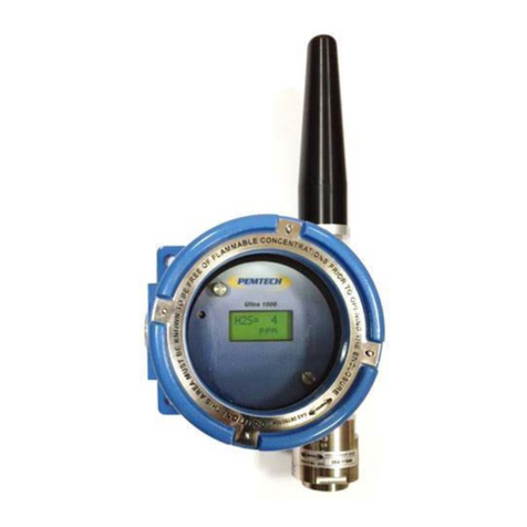
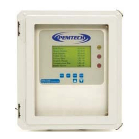
PEMTECH Ultra 1000 Series User manual

Ultra 1000
Wireless Gas Detector
Toxic and Combustible Hydrocarbons
Gas Detection Technology
Pem-Tech, Inc.
Houston, Texas
U.S.A.
www.pem-tech.com
Operator’s Manual
August 2016
Rev 2

Ultra1000 Wireless Detectors (Battery Operated) Rev 2 Page 2
NOTICE
PEM-TECH INCORPORATED SHALL NOT BE LIABLE FOR TECHNICAL OR EDITORIAL ERRORS OR
OMISSIONS MADE HEREIN, NOR FOR INCIDENTAL OR CONSEQUENTIAL DAMAGES RESULTING
FROM THE FURNISHING, PERFORMANCE, OR USE OF THIS MATERIAL.
LIMITED WARRANTY
Pem-Tech, Incorporated warrants all the equipment to be free from defects in workmanship and material.
The products will operate in conformance with the published specifications when subjected to intended
and proper usage for the period of one (1) year from the date of shipment.
The warranty provides only the benefits specified and does not cover defects which result from acts
beyond the control of PEM-TECH including, but not limited to: damage by accident, negligence,
tampering, or failure to operate in accordance with the procedures outlined in the Operations Manual.
PEM-TECH’s liability under no circumstances will exceed replacement of the unit claimed to be defective.
Tampering with the equipment and altering it for uses other than the intended use or replacement of
parts not supplied by the company, shall immediately void and cancel all the warranties with respect to
the affected products.
The warranties specified herein are in lieu of any and all other warranties, express or implied. In no
event, whether as a result of breach of warranty or alleged negligence, shall PEM-TECH be liable for
special or consequential damages, including, but not limited to, loss of profits or revenue, loss of
equipment or down time costs.

Ultra1000 Wireless Detectors (Battery Operated) Rev 2 Page 3
SERVICE POLICY
Pem-Tech has service facility at the factory. For all the repairs contact at our toll free number 1-800-
379-3894 or visit our website www.pem-tech.com
For all repairs call us for a Return Material Authorization number (RMA). Inform us briefly the
nature of the problem and obtain shipping address. Properly pack the equipment before shipping.
Also include your complete shipping address and contact name and phone number.
For non-warranty repairs you must provide the limit to repair costs. State if a quote for repair cost
is required before you can authorize the repair cost. For this an additional charge may be
applicable.
NOTE:
1. For all the repairs under warranty, serial number must be legible on the items being repaired.
2. Shipping point is FOB Houston.

Ultra1000 Wireless Detectors (Battery Operated) Rev 2 Page 4
TABLE OF CONTENTS
Page #
1.0 Specifications ………………………………………………… 5
2.0 Overview …………………………………………………….. 6
3.0 Setting up Wireless Detectors ………………………………. 7
3.1 Installing Detectors …………………………………. 7
3.2 Installing Batteries ……………………………………. 7
3.3 Power up Wireless Detectors ………………………….. 9
3.4 Programming Sensor Address and Zone ID …………… 10
4.0 Sensor Calibration ……………………………………………… 12
4.1 Adjusting Sensor Zero Only………………………………. 14
4.2 Calibration Errors and trouble shooting …………………. 16
4.3 Calibration Flow Chart ……………………………………. 17
5.0 Maintenance
5.1 Battery (Power) Pak …………………………………….. 18
5.2 Recharging batteries ……………………………………. 19
5.3 Replacing Sensor head assembly ……………………… 20
6Calibration Accessories and spare parts …………………………. 22

Ultra1000 Wireless Detectors (Battery Operated) Rev 2 Page 5
1.0 Specifications
Sensor Specifications
Sensor
Range
Response Time
H
2
S
0 – 100 ppm
T90 < 30 sec
CO
0 – 100 ppm
T90 < 30 sec
NH
3
0 – 50 ppm
T90 < 50 sec
O
2
0 – 25 %
T90 < 15 sec
SO
2
0 – 50 ppm
T90 < 120 sec
Contact Factory for other sensors.
Enclosure
Copper free Aluminum Instrument enclosure
CSA / UL / ATEX / IECEx Approved for Class I Division 1
Detector Housing
316 Stainless Steel
Weight & Dimension
4.5 Lbs ( 2Kg); 12”H x 6”W x 3.5”H (30.5cm x 15cm x 9cm)
Display
8 Character x 2 Line LCD Display
RF Frequency
900 MHz ISM Band, Frequency Hopping
OR
2.4 GHz ISM Band, frequency hopping wide band modulator
IEEE 802.15.4 Compliant
RF Certifications
FCC Part 15.247 USA
4214A 1208 Canada
ETSI Europe (2.4 GHz Only)
Operating Range
1500 meters with dipole antenna line of sight
12 Km with High gain Yagi directional antenna
Power Input
7.2 Volts rechargeable Lithium Power Pak
Battery Charger
(purchased separately)
Universal Wall mount charger with 2.1 mm x 5.5 mm jack.
Rated Output: 12VDC @ 3 AH
Operating Temperature
-40º F to +122º F (-40º C to +50º C) for H
2
S (LT Series Detector Heads)
-4º F to +140º F (-20º C to +60º C) for H2S (EX Series Detector Heads)
-4º F to +131º F (-20º C to +55º C) for CO, SO2 & Oxygen
-40º F to +104º F (-40º C to +50º C) for Ammonia

Ultra1000 Wireless Detectors (Battery Operated) Rev 2 Page 6
2.0 Overview
Ultra1000 series wireless sensor is used for air quality monitoring. The sensor detects toxic or
combustible gas in air and sends the signal to a Gas Monitor / Controller over a wireless data
network. A complete data packet is transmitted to the wireless controller (or receiver). The data
packet includes the current gas reading, sensor diagnostic data and battery voltage. The data
transmit interval depends on the current gas concentration. This interval is typically 1.5 to 2
seconds when the sensor is reading any gas. The data transmit interval is longer if the sensor is
in normal operation and there is no gas being detected by the sensor. This transmit interval is
optimized in order to maximize the battery life.
Figure
1. Wireless Sensor -Overview

Ultra1000 Wireless Detectors (Battery Operated) Rev 2 Page 7
3.0 Setting up Wireless Detectors
3.1 Installing Detector
Mount the detector to a flat surface or on a pole using pole mount kit. A tripod is also
available for a free standing detector unit. When mounting to a wall or flat surface use
proper hardware to have at least 4-5 inches between the wall and the sensor enclosure.
This is to have a sufficient gap between the antenna and the wall so that the radio signal
is not bouncing back and forth between the antenna and the wall.
Standard Pole Mount bracket or U-Bolt can also be used to mount the sensor.
3.2 Installing batteries
Note: Batteries are shipped separate from the wireless sensors.
To install the battery remove the cover of the sensor enclosure and the transmitter board
packed inside. Remove the 2 thumb screws and the flat battery holding plate from the
long posts mounted inside the enclosure.
Notice 2 each stand offs ( alignment posts) on the circuit board inside. When placing the
battery inside the enclosure the alignment posts should be in-line with the holes on the
bottom of the battery pack. This way the connector will properly snap into the receptacle
on the battery pack.
DO NOT wiggle the battery pack and apply excessive force to push the battery.

Ultra1000 Wireless Detectors (Battery Operated) Rev 2 Page 8
Once the battery pack in place
secure it with the flat holding pate
and 2 each thumb screws on the
mounting posts.
Install transmitter board assembly
on top of the battery pack. There
are two (2) each gold threaded
inserts on top of the battery pack. Engage
thumb screws on the transmitter board into
these inserts.
Connect the ribbon cable to the side of the
transmitter board assembly as shown in
figure 1

Ultra1000 Wireless Detectors (Battery Operated) Rev 2 Page 9
3.3 Power Up Wireless Detectors
First Time Detector Power Up
The detectors from the factory are shipped without batteries installed. Install the battery pack as
explained in previous section. Connect the ribbon cable to the transmitter board.
Power On / OFF Detectors:
Place the magnetic wand on top of the sensor enclosure to activate the internal power
switch. If needed move the magnet slightly left and right (between 11 and 1 O’ Clock
positions) to activate the switch. Remove the magnet when sensor startup messages
appear on the LCD.
See Figure 2.
To shut down the detectors when not in use place and hold the magnet on top of the enclosure
just like in power On mode for few seconds. Detector will display shut down message and will
shut down the power from the batteries in 5 seconds.
Figure
2. Sensor Power ON/Off with internal Magnetic Switch

Ultra1000 Wireless Detectors (Battery Operated) Rev 2 Page 10
3.3 Programming Sensor Address & Zone/Network ID
Initially the sensor must be assigned with a sensor Address (Unit ID) and Network / Zone ID. The
sensor address and zone id needs to be programmed only once. The data is retained in a non-
volatile memory and is not lost when the detector is powered down. Address and ID are recalled
from the memory when the unit is powered up again.
Note: The addresses to each sensor are assigned at the factory when a complete system is shipped.
However, when a single replacement sensor is purchased then user must assign the address to the
sensor.
In order for the detector to communicate with PT2000 Series Control Monitor or gateway each
sensor must be assigned a unique address. The sensor uses this address to identify itself when
transmitting data to the monitor/Gateway over wireless network. Network / Zone ID must also
be set. Network ID for all detectors must be the same as the Controllers Network ID. Network ID
is used to avoid any crosstalk between devices if multiple Systems are used within the
communication range of each other.
Follow the step by step instruction to assign a unique address to the sensor.
1. Using the magnet supplied with the unit, activate the internal magnetic switch. Refer to
figure 3 for the position of the Edit Configuration switch.
The switch is located on the transmitter board at 4 o’clock position. See Figure 3
2. The detector displays the list of parameters available for modifications one at a time on the
LCD.
Edit
Config
Set
Address.
Set
Zone ID
Exit ?
Set a unique address of the
detector. Address set between 1 and
64
Address
1
Zone ID
0 Set Zone Id between 0 and 9
Select to exit the configuration
menu. Else menu will scroll back
on top of menu

Ultra1000 Wireless Detectors (Battery Operated) Rev 2 Page 11
3. To change the address, select Set Address from the options by holding the magnetic
wand to the junction box at 4 o’clock position.
4. After few seconds the current Address will be displayed. Hold the magnet to change the
address ( 1 unit at a time). The maximum address limit is 64. The address rolls over to 1 after
reaching the limit. Move the magnetic wand away once the desired address is displayed on
the LCD. The address is now saved into memory.
5. The sensor will go back to scroll the Config options. Select the Set Zone ID from the
options by holding the magnetic wand to the junction box at 4 o’clock position.
6. To change the Zone ID hold the magnet until desired zone id is displayed on the LCD and
then move the magnet away.
7. Few seconds after the magnet is removed, the unit will save the zone ID and then return
back to the Config Options.
Note:
Network / Zone ID should be set to 0 unless multiple Controllers / Gateways are used within
the transmitting range of each other. The default Zone ID is 0 for all the gateways,
controllers and sensors shipped from the factory.
Magnet tool to activate
Internal switch
Figure
3. Edit Config Mode. Setting Unit Address & Zone ID

Ultra1000 Wireless Detectors (Battery Operated) Rev 2 Page 12
8. To Exit simply hold the magnet at 4 o’clock position and the sensor will return to normal
operation. The sensor may re-boot if the zone id is modified. The new zone ID will be
retained in the non-volatile memory and will be recalled upon next power up.
Caution
The default Zone ID is 0 set at the factory for all the detectors and the controller. In order for the
controller and the all the detectors on the Network to communication properly the Zone ID of all
the detectors and the controller must be identical. However, the sensor Address must be
distinct. It is recommended that the sensor addresses should all be in numerical order and any
address should not be skipped.
Zone ID should be modified or changed only if multiple wireless systems are being used in a
close proximity or within the communication range.
4.0 Sensor Calibration
Refer to Table at the end of this section for the recommended calibration gas for the target
sensor.
Following items are needed for the sensor calibration:
•Calibration adapter with tubing
•Magnet tool to activate the magnetic sensor on the transmitter board assembly.
•Calibration gas bottle with flow regulator. The flow of the calibration gas should be
approximately 1.5 LPM (liters per minute)
See Figure 5
The sensor can be auto calibrated without removing the enclosure cover and declassifying the
zone. A magnet tool is used to activate the internal switch to initiate the calibration.
Follow the steps below to calibrate the sensor.
1. Make sure the detector and ambient air is clear of gas vapors.
2. Remove the rain / splash guard if attached.
3. Place the magnetic tool against the cover at 8 o’clock position to activate the magnetic
switch as shown in figure 3.

Ultra1000 Wireless Detectors (Battery Operated) Rev 2 Page 13
4. Place and hold the magnet until display indicates the “Calib Sensor” . Move the magnet away
from the cover.
5. While the Calib Sensor message is being displayed the sensor is making its initial
adjustments. It may take 5 to 10 seconds. (Note: Do not apply calibration gas yet)
6. Once the initial adjustments are made the sensor will display the concentration of the
calibration gas to be applied. For example the display will show “Cal Gas 50 “. To match
the displayed Cal-Gas reading to the calibration gas bottle being used simply place and hold
the magnet to the cover at 8 o’clock position until the display reads the desired cal-gas value.
Typically the calibration is performed at mid scale. For example, the H2S sensor with the
detection range of 100 ppm the typical calibration gas should be 50 ppm. The selected
calibration gas value will be stored in the non-volatile memory and remains unchanged until
modified.
7. The microprocessor waits 60 seconds for the user to apply the calibration gas while flashing
the display approximately twice every second. Attach the calibration adapter to the sensor
head assembly and turn the gas on. When the flow of the gas is detected by the sensor the
display flashing rate will slow down to once every second. If no gas is detected within 60
seconds the sensor aborts calibration and will display error message “Calibration Time Out”
for few seconds before returning to normal operation..
8. Apply the calibration gas for about 2 minutes.
Magnet tool to activate
Internal switch
Figure 4. Activating internal magnetic switch for sensor calibration mode

Ultra1000 Wireless Detectors (Battery Operated) Rev 2 Page 14
9. After 2 minutes the sensor will display Adjustng for 5 to 15 seconds while making
adjustments and recording the calibration data into memory. When completed the display
will starts flashing rapidly. At this time remove the calibration gas and allow the sensor to
clear. Do not remove the calibration gas while the sensor is adjusting. Remove the gas only
when Calibration OK message is displayed.
10. The sensor calibration has been successfully completed and “Calibrat OK” message is
displayed for few seconds.
11. The sensor will return to normal operation once all the calibration gas is cleared out of the
sensor head and the reading goes to zero.
Also refer to “Sensor calibration Flow Chart” for quick calibration review and “Calibration Error
and remedies”
4.1 Adjust Sensor Zero Only
For sensors that have been in service for a long period of time may suffer an upward shift in zero
set point. That is the sensor might be reading a low gas concentration. This can be remedied by
adjusting the zero without performing the full calibration.
To Adjust the zero, follow the steps below
Assuming the ambient air is free of any toxic gases ( fresh air for oxygen sensor 21%)
Using the magnetic wand initiate the calibration model via internal magnetic switch on the
left side.
The sensor goes into calibration mode and after few seconds prompts the user to apply
calibration gas.
Once the “Cal Gas” message is displayed simply touch on the right side (4 o’clock positon) of
the enclosure for internal magnetic switch.
The message “Zero Adj – OK” will be displayed on the LCD.
The zero is adjusted and after few seconds the sensor will return to normal operation.

Ultra1000 Wireless Detectors (Battery Operated) Rev 2 Page 15
Recommended Calibration Gas for Target Sensor
Target Gas Recommended Calibration gas
Hydrogen Sulfide 50 ppm H2S Balanced in Air
Carbon Monoxide 50 ppm CO balanced in Air
Sulfur Dioxide 25 ppm SO2 Balanced in Air
Oxygen Deficiency Pure Nitrogen (for zeroing)
Combustible ( LEL) 50% LEL (2.5% Methane in air)
Figure
5. Applying Calibration gas to sensor

Ultra1000 Wireless Detectors (Battery Operated) Rev 2 Page 16
4.2 Calibration Errors, Trouble shooting and Remedies
Error 1: Sensor Zero too high.
The microprocessor was unable to make initial adjustment. The output from
the sensor-element is too high to adjust. This error can occur during step 4
of the calibration procedure. A short sensor-element could result in this
error. Check if sensor wires are connected properly and firmly to the sensor
terminals.
Error 2: Sensor Zero too low:
The microprocessor was unable to make initial adjustment. This error can
occur during step 4 of the calibration procedure. Check if the sensor wires
are not loose and are connected properly to the terminals.
Error 3: Calibration Time Out:
After initial adjustment the unit waits maximum of 60 seconds for the
calibration gas. Calibration is aborted if no calibration gas is detected by the
microprocessor. Check for the leaks in the calibration apparatus and check
the flow rate. Always use a calibration adapter and proper flow rate. A
completely dead sensor could also result in this error.
Error 4: Not enough Sensor reaction to gas:
At the end of the calibration cycle the microprocessor checks for the
adequate sensor reaction to the calibration gas. This error code is
displayed when sensitivity of the sensor to the calibration gas applied is
extremely low and the microprocessor is unable to make final adjustments.
This error can also occur when there is insufficient flow of the calibration
gas to the sensor. Also check if the calibration gas has not expired and be sure to use the
calibration adapter and check the calibration apparatus for leaks.
Calib Err
Low Zero
Calib Err
Time Out
Calib Err
No Gain
Calib Err
High Zero

Ultra1000 Wireless Detectors (Battery Operated) Rev 2 Page 17
Flow Chart
Sensor Calibration
User Action Sensor Display / Response
Initiate Calibration
via magnetic switch
magnetic switch
Calib Mode is
displayed for 5 to
10 seconds. Sensor
makes initial
adjustments
Calib gas value flashes
on the display and
sensor waits for the
gas to be applied
Apply Calib Gas within 60
seconds to avoid “Calibration
Time Out”. Change the value
of calibration gas being used if
required.
Display flashes calibration gas value at the
slower rate when the gas is detected by the
unit
Apply Calib Gas for 2
minutes
Display flashing once every
second
Calibration time ends
after 2 minutes approx.
Adjstng is displayed for few seconds.
Sensor is making final adjustments and
recording calibration data. Do not remove
the gas while this message is being displayed
Remove Calibration Gas
when message is prompted
on the LCD
Remove Cal-Gas message is
displayed on LCD.
Sensor Calibrated
Successfully. Returns to
normal operation once gas
cleared down to zero
Wait till display
flashes Calibration gas
value

Ultra1000 Wireless Detectors (Battery Operated) Rev 2 Page 18
5.0 Maintenance
5.1 Battery Pack
Wireless Alarm status uses PemTech This power pack is a complete module
with rechargeable lithium batteries with integrated battery charging circuitry. All built in and
encapsulated into a polycarbonate machined housing. This power module can be recharged
using a good quality desktop power supplies with 2.1 x 5.5 mm. The recommended charger can
be purchased from Pem-Tech, however, charger specifications (for third party supplier) are
listed in section Specifications Power Input.
Figure 3. Battery Pack
.LED indicators when charging, connecting to wall mount charger
LED Status Indicator
Jack for battery charger
Battery Pack
Wall Mount
Charger

Ultra1000 Wireless Detectors (Battery Operated) Rev 2 Page 19
5.2 Recharging battery pack
It is recommended to have a spare battery pack in order not to have any sensor down time.
Normally it take about 2-3 hours to completely charge the battery. It is up to the user to
determine how many spare batteries would be needed for a given number of detectors installed
in the facility.
The wireless detector monitors the battery voltage / level. When battery is low the
detector will send the low battery signal to the main controller. The low battery icon on
the control panel is displayed. At this time the battery should be recharged. ** Do not
run the sensor on low battery for long time as it effects the life of the battery.
Power Down the sensor. Loosen the thumb screws on the transmitter board and move
the board away from the battery. You may disconnect the ribbon cable connector to
completely remove the transmitter board.
** Do not remove the screws from the panel. ***
Remove the battery holding plate and carefully remove the battery from the battery
holder. Simply pull the battery from the housing. DO NOT wiggle the battery to remove.
A wall mount battery charger is required to charge the battery pack. Insert the charger
jack into the receptacle on the lower side of the power pack assembly. See figure 3.
3 LED status indicators are provided on the bottom of the battery pack. The function of
these LEDs are explained in table below.
When the green LED is completely off then the battery is completely charged and ready
for use.
Table 1
LED indicators during battery charger plugged in
For longer battery life, the battery must not be used for long time once the low battery is
detected. The wireless sensor indicates with the battery is at low level. Batteries should be
recharged at this stage. The nominal battery charge time is approximately 2 – 3 hours.
LED Color / Status
Description
Yellow & Green
Battery is being charged (fast charge)
Green
Slow charge
No LEDs
Battery completely charged
Red
Bad battery

Ultra1000 Wireless Detectors (Battery Operated) Rev 2 Page 20
5.3 Replacing Sensor Head Assembly
Replacing the Stainless Steel sensor head assembly requires to dismantle the base circuit board
assembly from the bottom of the enclosure. However, does not require to disconnect the
antenna cable. The antenna cable is secured with a tie wrap and should not be disconnected from
the wireless transceiver on the bottom of the circuit board. Also precaution should be taken for
proper handling of the circuit board assembly.
Follow the procedure below to replace the sensor head assembly. See Figure 4 (next page),
bottom view of the circuit board assembly.
Power off the detectors as explained in section 1
Remove transmitter board assembly by detaching the ribbon cable connector
Remove the battery holding plate, disconnect and remove the battery from the base circuit
board assembly.
The circuit board is mounted inside the enclosure via 3 machine screws. Remove the
screws and slowly pull the circuit board out of the housing.
Pull and slowly flip the board upside down. Disconnect the four pin wire plug connecting
the sensor head wires from the circuit board. Let the circuit board hang aside on the
enclosure.
Unscrew the stainless steel sensor head assembly and detach it from the sensor junction
box.
Disconnect the wires from the 4-pin plug (Sensor Terminal). Connect the new sensor wires
on the plug.
****** Note the Color code of the wires connection to the plug ******
Engage the new sensor housing into the threaded entry of the junction box. . Lubricate the
threads slightly if needed.
Connect the 4-pin plug to the receptacle on the circuit board. Recheck the wires
connection confirm the color codes. Also make sure the ribbon cable is firmly connected
to the connector on the bottom of the PCB assembly.
Other manuals for Ultra 1000 Series
1
Table of contents
Other PEMTECH Gas Detector manuals
Popular Gas Detector manuals by other brands

SENSIT Technologies
SENSIT Technologies GOLD G3 instruction manual

Atest Gaz
Atest Gaz SmArtGas 4 user manual

Honeywell
Honeywell BW Ultra user manual

ION
ION SF6 P2 user manual

Mircom
Mircom CO1224T quick start guide

United Electric Controls
United Electric Controls UE VANGUARD WirelessHART TCD60HXY Installation and maintenance instructions