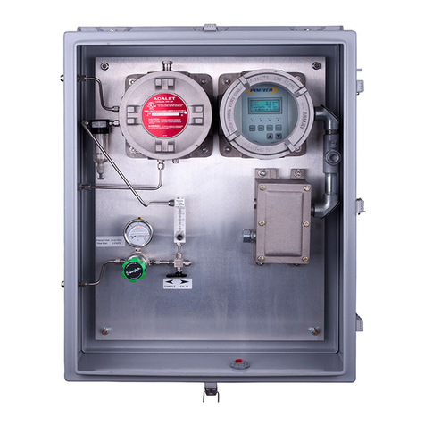
PEMTECH PT605 User manual

Gas Detection Technology
PT605
Dual Gas Analyzer
H2S & CO2
Revision 7
February 2010
Operator’s
Manual
Pem-Tech, Inc.
Houston, Texas
U.S.A
www.pem-tech.com

2
Table of Contents
Sections Page No.
Specifications 5
Operation 6
Overview 7
PT605 Analyzer –Block Diagram 7
Figure 1. PT605 –Unit Layout 9
Front Panel 10
Clear Cycle 11
H2S Sample Cycle 11
Messages and reading display during 11
Normal sampling cycle
Alarm LEDs and keypad switches 12
Installation and Unit Startup 13
System Wiring 13
Power Supply Input 15
AC Power Input 15
DC Power Input 15
4-20mA Analog output 15
User connection and wiring diagram 16
Alarm Relay contacts 17
RS232 / 485 Serial Communication 17
Connecting Gas stream to the Analyzer 17
Unit startup check list 18
STOP –Important Installation and 19
Maintenance note
Sensor Calibration 20
H2S Sensor Calibration 21
Sensor calibration procedure 21
Tips on good calibration 23
Sensor calibration errors 23
CO2 Sensor Calibration 24
Sensor calibration procedure 25
Tips on good calibration 27
Sensor calibration errors 27
(continue on next page)

3
Table of Contents (continued)
Sections Page No.
Fine tuning of 4-20mA analog output 28
Alarm Relays 29
Programming Alarm levels 29
MODBUS RTU Communication 31
Edit / Assign unit address 31
MODBUS Communication and 32
Data register list
Replacing Analyzer Sensor Assembly 34
Care 35
Maintenance 35
Spare Parts List 36

4
NOTICE
PEM-TECH INCORPORATED SHALL NOT BE LIABLE FOR TECHNICAL OR
EDITORIAL ERRORS OR OMISSIONS MADE HEREIN, NOR FOR INCIDENTAL OR
CONSEQUENTIAL DAMAGES RESULTING FROM THE FURNISHING,
PERFORMANCE, OR USE OF THIS MATERIAL.
LIMITED WARRANTY
Pem-Tech, Incorporated warrants all the equipment to be free from defects in
workmanship and material. The products will operate in conformance with the
published specifications when subjected to intended and proper usage for the period of
one (1) year from the date of shipment.
The warranty provides only the benefits specified and does not cover defects which
result from acts beyond the control of PEM-TECH including, but not limited to: damage
by accident, negligence, tampering, or failure to operate in accordance with the
procedures outlined in the Operations Manual. PEM-TECH’s liability under no
circumstances will exceed replacement of the unit claimed to be defective.
Tampering with the equipment and altering it for uses other than the intended use or
replacement of parts not supplied by the company, shall immediately void and cancel
all the warranties with respect to the affected products.
The warranties specified herein are in lieu of any and all other warranties, express or
implied. In no event, whether as a result of breach of warranty or alleged negligence,
shall PEM-TECH be liable for special or consequential damages, including, but not
limited to, loss of profits or revenue, loss of equipment or down time costs.

5
SERVICE POLICY
Pem-Tech has service facility at the factory. For all the repairs contact at our toll free
number 1-800-379-3894 or visit our website www.pem-tech.com
For all repairs call us for a Return Material Authorization number (RMA). Inform us
briefly the nature of the problem and obtain shipping address. Properly pack the
equipment before shipping. Also include your complete shipping address and contact
name and phone number.
For non-warranty repairs you must provide the limit to repair costs. State if a quote for
repair cost is required before you can authorize the repair cost. For this an additional
charge may be applicable.
NOTE:
1. For all the repairs under warranty, serial number must be legible on the items being
repaired.
2. Shipping point is FOB Houston.

6
SPECIFICATIONS
Typical Range: H2S: 25 ppm, & 200 ppm
CO2: 5%, 10%
(Other Ranges also available)
Range is pre-programmed at the factory
Electrical Classification: Class I Div 1, Suitable for use in Hazardous
Location
Weight 70 Lbs (31.8 Kg)
110 Lbs (49 Kg ) with Fiberglass enclsoure
Sample Gas Physical properties: Dry and particle free
Temperature: 10 F to 110 F (4 C to 50 C)
Sample inlet Tube Fittings: ¼” Stainless Steel tube fittings
Repeatability: When challenged with same calibration gas,
H2S: within 0.5 ppm (analyzer with 25 ppm range)
2 ppm (analyzer with 200 ppm range)
CO2: within 0.2 %
Accuracy: 3 %
Alarm Relays: 3 SPDT fully programmable dry relay contacts Form “C”
Type . Rated 5 amps @ 125 VAC or 24 VDC
Analog Output: 4-20 mA ( 350 maximum loop resistance )
Display: 4 lines by 16 character LCD display with backlight
Supply Voltage: 18-28 VDC
117 VAC (240 VAC option available)
Power Consumption: < 4.5 watts

7
Sampling System Junction Box
Main Electronics and Control Assemblies
Termination / User
connection Box
Dry Sample in
¼ Tube Fitting
vent
Air Intake
PT605 Analyzer –Block Diagram
OPERATION
Overview
The following figure illustrates an overview of the units operation. Refer to figure 1 for
complete system layout.
When the power is applied to the unit it will display startup messages such as current alarm set
points, background or interference gas settings and sensor calibration data.
After the startup messages the system will begin the warm up cycle for approximately 10
minutes (600 seconds). This allows the sampling system to clear and perform initial diagnostic
tests.
H2S Measurement: For the measurement of H2S concentration the analyzer performs sample &
purge routine. The analyzer samples the on-stream gas for 90 seconds and then purges for 180
seconds. At the end of sample cycle the internal solenoid valve is switched off and ambient air
is pumped into the sampling system to purge. The final H2S reading is updated on the display,
4-20mA output is generated and alarm relays are energized if the H2S concentration exceeds
the preset alarm levels.
Sample Conditioning
Pressure Regulators
External Filters
CO2
Sensor Asmbly
Main CPU Board Assembly
Control Logic
Flow Meter +
Coalescing Filter
H2S
Sensor Asmbly
Solenoid
Valve
Gas Sample
routing & Vent
block with tube
Purging Pump
Terminal Blocks
4-20mA
Alarm Relays
AC / DC power Input
Sensor Signal conditioning
AC-DC , DC-DC power convertors. Alarm
relays

8
CO2Measurement: The measurement of CO2is continuous. The on-line gas is continuously
being diffused into the Infra-red CO2sensor sampling assembly. The CO2 reading is updated
every second on the display. Also 4-20mA is generated and alarm relays are energized if CO2
concentration exceeds the preset alarm levels.
Note:
In an installation where ambient air is contaminated with H2S and other toxic gases, it is recommended
that clear instrument air must be used. The instrument air should be connected to the air intake located
below the sampling system enclosure.

9
Figure 1. PT605 Analyzer in fiberglass enclosure. Complete unit layout

10
Front Panel
PT605 front panel is equipped with a large liquid crystal display with back light, four alarm
LEDs for visual alarm indicators, and keypad switches. The H2S & CO2concentration and
sample and clear mode are displayed on the LCD. The keypad switches are used to reset
alarms, calibrate sensors and program unit configuration.
Following are the prompts and messages on the LCD during sample and clear cycle.
Front Panel Assembly
LCD Prompts & Messages
During Clear Cycle During Sample Cycle
The first and second line on the LCD displays the concentration of the H2S and CO2. The third
line indicates when the analyzer is sample or Purge mode for the H2S measurement. The last
line indicates the status or signal strength of the sensors. If in clear cycle E1 is the signal level
for the H2S sensor while E2 is the signal level of the CO2 sensor. If the analyzer is in H2S
sampling mode then the last line indicates the change is H2S sensor signal in ppm and voltage.
In Clear Cycle as the sensor is purged with air the E1 reading would decrease while during the
H2S = 00 ppm
CO2 = 00 %
Clear Tm 30 Sec
E1=0.90 E2= 0.40
H2S = 00 ppm
CO2 = 00 %
Sample Tm 30 Sec
2.0 ppm * 1.2V

11
sampling cycle the gas reading increases as the H2S concentration in the sampling chamber
increases.
The data on the last line of the LCD is simply used as a diagnostic and troubleshooting feature
Clear Cycle
During normal operation the duration of the clear cycle is 3 minutes. An internal solenoid
valve is switched off during this cycle restricting the flow of sample gas through the H2S sensor
assembly and allowing the sensor to purge with ambient air. During the clear cycle the H2S
sensor signal (E1) displayed on the last line of the LCD decreases. The gradual decline in the
reading indicates that the sensor is being purged properly. In an event when this reading does
not decline close to zero the analyzer will allow an additional 30 seconds to purge before taking
another sample for analysis. Check the purging pump to be sure if it is functioning properly.
H2S Sample Cycle
The duration of sample cycle is 90 seconds. During this cycle the solenoid valve is switched
open to allow the sample gas to pass through the H2S sensor assembly. While the sensor is
being exposed to the gas containing H2S the “instantaneous” H2S-ppm reading and the sensor
signal strength increases as is displayed on the last line of the he LCD. At the end of the
sample cycle the H2S reading on the first line of the LCD is updated . Also an equivalent 4-
20mA analog output will be generated and alarm relays (if configured) will be activated if the
H2S concentration exceeds the alarm level.
LCD messages during normal sampling cycle
H2S = 00 ppm
CO2 = 00 %
Sampl Tm 20 sec
2.0 ppm * 1.2 V
H2S Concentration in the last sample cycle. Reading is
updated after completion of each sample cycle
Current CO2 gas concentration. Updated every
second.
Time remaining in the current sampling cycle.
Instantaneous H2S reading and Signal from the
sensor.
The signal steadily increases when the analyzer is in
the sampling cycle and decreases during the purge or
clear cycle.

12
Alarm LEDs and Keypad switches
There are 4 LEDs on the front panel labeled AL1 thru AL3 and a Fault LED. These LEDs are the
visual indicators of any active alarms. The alarm relays and LEDs can be reset by pressing the
RESET key on the front panel. The resetting of the alarms via reset switch can only be
performed in the clear cycle.
When the “PRGM”(program) key switch is pressed the unit will initiate a sequence of prompts
giving user option to select one by pressing the ENTER key. The list of option includes:
H2S Sensor Calibration
CO2 Sensor Calibration
Adjust H2S Alarms
Adjust CO2 Alarms
4-20mA Adj –H2S
4-20mA Adj –CO2
Set Unit Address
Adjust H2S Calibration
Display Calib data

13
Installation and Unit Startup
PT605 analyzer should be installed approximately 5 feet above the ground. A ¼”
stainless steel tubing should be used to connect the sample input of the analyzer to the
stream. A minimum of 50 PSIG sample stream pressure is required. The maximum inlet
pressure of the installed pressure regulator is 2000 PSIG with maximum output
pressure of 30 PSIG. The analyzer sampling system requires a flow rate of one (1.0)
SCFH.
For stream with high pressure an external pressure regulator close to sampling point
must installed to reduce the pressure before connecting to the analyzer.
For streams with heavy moisture contents and other contaminants an additional in-line
filter must be installed.
Important Note
PT605 requires a clean and dry gas sample from the process stream for
proper operation. The sample input must be at a minimum pressure of 50
PSIG and must have a regular flow through the sampling system. All vent
fittings must be left open to atmosphere and should not have any back
pressure.
Refer to figure 1 for the location of the junction box with customer connection and
terminals. Also refer to figure 3 for connections and wiring diagram. The connection
box has 2 each ¾” NPT female cable entry ports. Install proper cable glands (user
supplied) for the type of cable being installed. Also a ¾” conduit hub is provided on
the bottom of the fiberglass enclosure for cable entry inside the fiberglass enclosure.
PT605 Analyzer is suitable for use in hazardous location. The unit can be mounted to
the wall or panel. Refer to figure 2 for the mounting holes and dimensions on the
fiberglass enclosure. Six (6) mounting holes are provided on the enclosure for wall
mounting.
The analyzer should be installed approximately 5 feet above the ground. Extreme
temperature condition must be avoided. Avoid installing the unit with the front facing
the direct sunlight.

14
Figure 2. Fiberglass Enclosure for PT605 Analyzer

15
System Wiring
Three junction boxes are installed on the right side of the analyzer. Each of these junction boxes
have cable conduit entrance of ¾” NPT.
Inside each of the junction boxes there are connection boards with screw type terminal
connectors. Each terminal is labeled appropriately for AC or DC power, 4-20mA and dry alarm
relay outputs.
See figure 3 for the customer connection boards inside the junction box.
Power Supply Input
The analyzer operates on either AC or DC power supply. A standard 117 VAC or 24 VDC
power is supplied to the unit.
AC Power Input:
A screw in type terminal connector is provided in the top customer connection junction box for
AC power input. The terminal block is labeled “L N G”.Pull the 3-pin connector plug from
the socket, connect the 117 VAC power supply lines to the proper pins and insert the plug back
into the socket.
DC Power Input:
If the unit is powered by DC, connect 16 –24 VDC supply to the 2 pin DC power input
terminal in one of the junction boxes. The terminal is clearly labeled as DC IN on the customer
connection board. Simply connect the positive and negative supply lines to the connector pin
labeled as + and -, respectively.
Note
The analyzer is DC operational only if it is not equipped with the AC input terminal on the customer
connection board assembly.
4-20mA analog output:
PT605 Analyzer generates a linear 4-20mA DC analog output equivalent to H2S concentration
in the stream. This analog output can be connected to devices like PLC, DCS and chart
recorders. The analog output generated corresponds to the full scale of the analyzer.
Table below gives the corresponding mA reading for an analyzer with the full scale range of 25
ppm H2S and 10% CO2. The gas concentration vs. (analog output) mA will be different for the
unit with different full scale range.
ppm - H2S
Analog Out
mA
00
4.0
10
10.4
20
16.8
25
20.0
% - CO2
Analog Out
mA
0.0
4.0
2.5
8.0
5.0
12.0
7.5
16.0
10.0
20.0

16
Figure 3. User connection and Terminations for Power, alarms,
and 4-20mA analog output

17
Alarm Relay Contacts:
The analyzer is equipped with 3 each dry alarm relay contacts (potential free). Each relay can
be programmed anywhere between 0 and the full range of the analyzer.
The relays are Form “C” type relays. On the customer connection board each alarm terminal is
labeled appropriately. An alarm terminal is a 3 pin terminal labeled as:
NO Normally Open
C Common
NC Normally closed
Use “C” and “NO” terminal for normally open contacts and “C” and “NC” terminals for
normally closed contacts.
RS232 / RS485
The serial port RS232 or RS485 (jumper selectable) is provided for communication with PLCs.
Industry standard MODBUS RTU ® protocol is used for data communication. Refer to
section on MODBUS Communication later in this document for additional details.
Connecting the gas stream to the analyzer
PT605 requires a clean and dry gas sample from the process stream for proper operation. A
minimum of 50 PSIG line pressure is needed. In normal operation the pressure should not
exceed 500 PSIG. The regulator installed on the analyzer has maxim inlet pressure rating of
2000 PSIG with 30 PSIG on the output port. However, a drastic pressure drop from over 2000
PSIG to 30 PSIG will increase the temperature of the gas which could be damaging to the
sampling system over the extended period of time. For high-pressure stream an additional
pressure-reducing regulator must be installed at the sampling point. A ¼” stainless tube shall
be used to connect sample stream to the pressure regulator on the analyzer.
An additional in-filter must be used for stream with high moisture content and contaminants.
The in-line filter installed on the unit is coalescing filter to remove the residual contaminants
from the gas sample.
Be sure to shut off the pressure regulator (turn counter-clockwise) before flowing the gas to the
analyzer.
Use the unit startup checklist on the next page for proper step by step startup.

18
Unit Startup Check list
Use the following steps as a guide for proper startup procedure.
Unit must be installed in shaded area to avoid extreme heat conditions.
Perform all the system wiring as discussed in the previous section.
Be sure the unit is connected with proper AC or DC supply. But DO NOT switch the
power ON at this time.
Secure and tighten all covers to the junction boxes.
Check for maximum stream pressure and temperature. For high pressure streams install a
regulator at the sampling point and then run ¼” tubing to the analyzer regulator. Do not
connect stream with high pressure straight to the regulator installed on the analyzer.
Be sure the stream is free of heavy particles, contaminants and heavy moisture to avoid
damage to the sampling system.
Shut off the regulator on the analyzer by rotating the knob counter clockwise.
Connect the stream to the analyzer via ¼” stainless steel tube.
Make sure the 3 - way valve next to the pressure regulator is switched to “SAMPLE”
position.
Switch ON the AC or DC power to the analyzer. The LCD should display start up
messages.
After start up messages and warm up cycle the unit will begin its normal operation. If
alarm relays are being used then set alarm levels when the system is in clear cycle. Refer
to section on programming alarm set points later in this document.
Switch ON the flow from the gas stream.
Slowly turn the pressure regulator knob in clockwise direction to start the sample flow to
the analyzer. Set the pressure between 25 and 30 PSIG indicated on the pressure gauge.
Set the flow rates on the flow meter to 1.0 SCFH. The flow meter is located right above
pressure regulator and 3-way valve. See System layout diagram.
The analyzer is calibrated at the factory and is therefore, ready for normal operation.
However, if the user wishes to calibrate the unit then wait for at least 5 to 6 sample and
clear cycles with stream gas flowing before attempting the calibration.

19
Important Installation & Maintenance Note
Do not block Vents on the system enclosures.
There is Vent tube fitting located one top left corner of the system enclosure. Blocking vent
or attaching a long tubes on vents will create back pressure that may result in sensor
contamination. If the installation of the vent tubes is necessary then keep the tubes as
short as possible and at least ¼” diameter. Also the tubes must point down in order to
minimize the atmospheric pressure on the tube openings.
If multiple Vent tube fittings are installed then these must not be “Tee” together into a
single vent. Each vent must have a separate vent tube.
Turn off the sample valve if the purging pump is not running.
It is imperative that the sampling system must be purged after each sample. An internal
pump purges the sampling chamber with fresh ambient air. If the purging pump
malfunctions or when the flow rate in the air flow meter is not at least 1 SCFH then shut
off the flow regulator to the analyzer. Pump failure or the purging with the contaminated
ambient air will result in sensor failure.
Ambient Air for purging.
In an installation where ambient air is contaminated with H2S and other toxic
gases, it is recommended that clear instrument air must be used. The instrument
air should be connected to the air intake located below the sampling system
enclosure.
Do not block the air intake port
Be sure not to attach any tubing on the air intake port that may obstruct in the air flow into
the sampling system. The internal pump draws air from this port for purging.

20
Sensor Calibration
Typically the H2S & CO2concentration of the calibration gas should be close to 50% of
the full scale range of the analyzer. The following table lists the calibration gas for
analyzer with different full scale range.
It is important that the composition of the calibration gas should resemble the composition of
the stream being analyzed. For example, a unit monitoring methane or natural gas stream
containing H2S should be calibrated with methane balanced H2S standard.
Do not use Nitrogen balanced H2S to calibrate H2S sensor.
The sensor calibration is performed simply by pressing the PRGM switch and following the
prompts on the LCD. The user is not required to make any kind of hardware adjustments.
The calibration procedure is fully automated. The analyzer will display messages on the LCD
and prompts for the user input when needed. When the calibration sequence has been
initiated the analyzer will prompt user to adjust/enter the H2S concentration of the calibration
gas being used after which a one-minute purge cycle is initiated. The user is then prompted to
apply the calibration gas. The microprocessor then makes all the adjustments necessary and
stores the calibration data in a non-volatile memory. The analyzer will display the message for
any calibration errors, otherwise a “Calibration OK” message is displayed and the unit will
return to normal operation.
If the user wishes to check the calibration then simply apply the calibration gas when the
analyzer is in normal sampling cycle and check if the analyzed H2S reading is the same as the
calibration gas within a specified tolerance.
Important Note
When performing the calibration check if the H2S concentration of the calibration gas applied is greater
then the alarm set points configured then alarm relays will be activated and 4-20mA analog output will
be generated equivalent to the H2S in calibration gas. Be sure that steps have been taken to bypass or
deactivate the devices connected to the alarm relay contacts of the analyzer.
Note: To abort the sensor calibration at any time press
RESET
switch. The unit will display the
sensor abort message for few seconds before returning to normal operation.
H2S Range
Recommended
Calibration Gas
25 ppm
10 –14 ppm
100 ppm
40 –50 ppm
200 ppm
80 –100 ppm
300 or 500 ppm
100 –200 ppm
CO2Range
Recommended
Calibration Gas
(nitrogen Balanced)
5%
2.5%
10 %
5.0 %
20%
10 %
50%
25 %
Other manuals for PT605
1
Table of contents
Other PEMTECH Measuring Instrument manuals