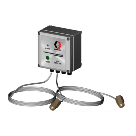
Graco Pulse TEK 811 Setup guide

3A8551E
EN
Installation, Operation, and Service
Pulse® Level Cellular
Tank Level Monitor
Measures the distance between the device and the surface of the fluid to determine the volume of fluid
within a tank. For use only with Pulse Level. Intended fluids: oil, diesel, waste oil, automatic transmission
fluid (ATF), kerosene, anti-freeze, windshield washer solution, waste water, and DEF. For professional use
only. Not suitable for tank overfill protection.
Not approved for use in explosive atmospheres or hazardous (classified) locations.
Part No. Model Description
Radio
Approvals Model Approvals
25T461 TEK 811 Pulse Level Cellular
North America
FCC, IC
133620 TEK 811 Pulse Level Cellular
International
CE, RCM
Important Safety Instructions
Read all warnings and instructions in this
manual and in all related Pulse manuals
before using the equipment. Save all
instructions.
WARNING
EQUIPMENT MISUSE HAZARD
Misuse can cause death or serious injury.
• Do not alter or modify equipment. Alterations or
modifications may void agency approvals and
create safety hazards.
• Make sure all equipment is rated and approved for
the environment in which you are using it.
• Use equipment only for its intended purpose. Call
your distributor for information.
• Keep children and animals away from work area.
• Comply with all applicable safety regulations.
PERSONAL PROTECTIVE EQUIPMENT
Wear appropriate protective equipment when in the
work area to help prevent serious injury, including
eye injury, hearing loss, and inhalation of toxic fumes.
This Tank Level Monitor (TLM) contains FCC ID XMR
201707 BG96. This device complies with Part 15 of the
FCC Rules. Operation is subject to the following two
conditions:
• This device may not case harmful interference.
• This device must accept any interference received,
including interference that may cause undesired
operation.

Installation
2 3A8551E
Installation
Set Up
Register TLM to Tank in Pulse
Level Software
Navigate to URL: level.gracopulse.com
This device requires access to a cellular network to
work, and can be activated in Pulse Level. Refer to
Pulse Level terms of service in the About section of the
software.
After creating user, organization, branch and site,
navigate to Devices (located in the upper right corner of
the screen). Associate the device to your organization
by entering the serial number. When you create a tank
for the site, the device will be assignable.
Assign the TLM serial number to a tank in Pulse Level.
Activation
1. Hold the magnet (supplied) to the Hot Spot directly
under the LED to activate the device (FIG. 1).
2. Keep holding the magnet to the Hot Spot. The LED
will flash green, and then flash red. Then the red
light will stay lit.
3. Remove the magnet.
4. While the red light is illuminated, a series of beeps
occur as the device connects.
5. Successfully connecting is indicated by a
high/low/high series of beeps that indicate the data
is being sent to Pulse Level. The LED turns green
after data is successfully sent.
6. Once activated, the device uploads readings at
scheduled times, if assigned to a tank in Pulse
Level.
• The device measures the tank liquid level.
NOTICE
• Do not over tighten TLM into tank bung. Over
tightening can cause permanent damage and
result in inaccurate readings.
• Do not use the TLM with pressurized tanks. Using
the TLM in a pressurized tank will damage the
TLM.
• Do not use thread sealant or adhesive. Many of
these products are chemically incompatible with
the ABS plastic.
FIG. 1
Hot Spot
LED light

Installation
3A8551E 3
LED Pattern
Beep Pattern
Typical Installation
Mount Options
Identify a threaded opening on the top of the tank for
the device to be installed. The location should be
vertical with a clear path to the contents of the tank.
There should be no obstructions that could interfere
with the signal. Insert the threaded device by screwing
it into the opening. Do not over tighten.
1. If the hole is not threaded, place the foam gasket
(included with kit) over the opening.
2. Place the mounting adapter (included with kit) on
top of the foam gasket.
3. Use the two (2) stainless steel self-tapping,
counter-sunk screws (included with kit) to attach
the adapter to the tank. Do not over tighten.
4. Attach the device to the adapter. To form a secure
seal, make sure that the device is vertical on the
tank, that it is secured correctly to the base, and
that the threads have not crossed.
NOTE: If the tank does not contain a suitably positioned
opening at the top of the tank, reference Drilling,
page 4.
LED Pattern Function
LED Test: when a magnet is held
against the hot spot, the LED is
briefly green, followed by briefly
red, then the LED is off.
Red LED Lit Modem Busy: registering on the
network and sending data.
Green LED Lit
Activated: the server has
responded and activated the
server.
Beep Pattern Definition
Low beep once per
second Network registration
High beep once per
second TCP connecting
Low beep once every
four (4) seconds
Network / TCP listen for
commands
Low beep once every two
(2) seconds Re-establish network / TCP
High /Low combination
beep Incoming data
Low / High combination
beep Outgoing data
Low double beep every
four (4) seconds
Network listen (data
received and the device is
active)
FIG. 2

Installation
4 3A8551E
Installation Examples
Drilling
If the tank does not contain a suitable positioned
opening at the top of the tank, it will be necessary to
manually drill into the top of the tank.
1. Select a flat area on the top of the tank located
towards the center (FIG. 3).
2. Drill a 1.5 in. bsp hole at the selected area using a
45.5 mm tapping drill.
3. Continue with Activation.
FIG. 3

Operation
3A8551E 5
Operation
View Data
The TLM is configurable with Pulse Level
(level.gracopulse.com) to take readings at predefined
times.
After configuring the TLM using the Pulse Level, apply
the magnet to the hot spot until a solid red light
appears, creating a connection between the TLM and
the Pulse Level to load the configuration (FIG. 4).
NOTE: Frequent measurements results in shorter
battery life.
Manual Measurement
1. Hold the magnet (supplied) to the Hot Spot directly
under the LED to activate the device (FIG. 1).
2. Keep holding the magnet to the Hot Spot. The LED
will flash green, and then flash red. Then the red
light will stay lit.
3. Remove the magnet.
FIG. 4
Magnet
Hot Spot FIG. 5
Hot Spot
LED light

Recycling and Disposal
6 3A8551E
Recycling and Disposal
End of Product Life
At the end of the product’s useful life, dismantle and
recycle it in a responsible manner.
• Remove batteries, circuit boards, LCDs (liquid
crystal displays), and other electronic components.
Recycle according to applicable regulations.
• Do not dispose of batteries or electronic
components with household or commercial waste.
• Deliver remaining product to a recycling facility.

Troubleshooting
3A8551E 7
Troubleshooting
Problem Cause Solution
Device is not reporting scheduled
readings.
Out of RF range.
RF obstruction.
Consider implementing a WiFi
network and using Graco’s WiFi
TLM.
Ensure that the TLM is not encased
in metal, since this would obstruct
the signal.
Weak or dead batteries. Replace batteries. See Replace
Batteries, page 8.
Tank Level Monitor was not
associated with a tank in software.
Assign TLM serial number to tank.
Reading is scheduled when pump
is operating.
Ensure readings are scheduled
during times that the pump is not
operating.
LED will not turn on. Magnet removed too soon. Hold magnet to device hot spot for
a longer period of time.
Try using a stronger magnet.
Weak or dead batteries. Replace batteries. See Replace
Batteries, page 8.

Service
8 3A8551E
Service
After the TLM has been installed, the only additional
maintenance or service necessary is changing the
batteries.
Replace Batteries
NOTE: After battery placement, activate the TLM with a
magnet (see Activation, page 2), to synchronize the
TLM internal clock to maintain scheduled TLM
readings.
1. Remove the TLM from the tank by unscrewing it
from the opening.
2. Remove the four (4) screws that keep the case
together (FIG. 6).
3. Verify that the device is right side up before
opening to prevent the batteries from falling out
(FIG. 7).
4. Replace the four (4) C-cell Alkaline batteries
(FIG. 8).
WARNING
Fire and Explosion Hazard
Sparking can occur when changing batteries. Only
replace the batteries in a non-hazardous location
away from flammable fluids and fumes.
FIG. 6
FIG. 7
FIG. 8
Bottom
Top
Negative (-) Positive (+)

Dimensions - Tank Specifications
10 3A8551E
Dimensions - Tank Specifications
Vertical Tank:
• Maximum Volume - 999,999 gallons or liters.
• Tank walls must be uniformly vertical from empty
level to full.
Cylindrical Tank:
• Maximum volume = 999,999 gallons or liters.
• Tank end walls must be flat; they cannot be any
other shape, including belled.
Obround Tank:
• Maximum volume = 999,999 gallons or liters.
• Tank end walls must be flat; they cannot be any
other shape, including belled.
Non-Standard Tanks:
• Maximum volume = 999,000 gallons or liters.
• Define strapping table in Pulse Level software.
• Up to 100 strapping table points to correlate tank
fluid height to volume.
FIG. 10
FIG. 11
FIG. 12
Width

Technical Specifications
3A8551E 11
Technical Specifications
California Proposition 65
Tank Level Monitor (TLM)
US Metric
Compatible Fluids oil, kerosene, diesel, lubricants, additives, DEF/AdBlue®,
coolants, water, waste oil, waste water, automatic
transmission fluid (AFT), anti-freeze, and windshield washer
solution
Ultrasonic Tank Depth Measurement range 5.0 in. to 13 ft. 12 cm (minimum) to 400 cm
Fluid Level Measurement Accuracy +/- 1.0 in. +/- 2.0 cm
Mounting 1.5 in and 2.0 in. threaded npt connector
Clearance: Height above tank for TLM 7.5 in. 19.1 cm
Weight 1.17 lb. with batteries 530.7 g with batteries
RF Frequency Band LTE CAT-M1
Operating Temperature Range 0°F to 122°F -17.8°C to 50°C
Storage Temperature Range -22°F to 140°F -30°C to 60°C
Batteries 4 x Alkaline C-cell
Battery Life 5 years*
Enclosure (Ingress Protection) IP67
Tanks
Maximum Volume 999,999 gallons 999,999 liters
Maximum Height 13 ft. 400 cm
Altitude <6,000 ft. < 2 km
* The battery life is based upon four (4) measurements per day and one (1) Cellular connection per day from a location
where the cellular coverage does not require retries, and a normal distribution over the operating temperature range
centered at +25°C (77°F).
All trademarks or registered trademarks are the property of their respective owners.
CALIFORNIA RESIDENTS
WARNING: Cancer and reproductive harm – www.P65warnings.ca.gov.

All written and visual data contained in this document reflects the latest product information available at the time of publication.
Graco reserves the right to make changes at any time without notice.
Original instructions. This manual contains English. MM 3A8551
Graco Headquarters: Minneapolis
International Offices: Belgium, China, Japan, Korea
GRACO INC. AND SUBSIDIARIES • P.O. BOX 1441 • MINNEAPOLIS MN 55440-1441 • USA
Copyright 2021, Graco Inc. All Graco manufacturing locations are registered to ISO 9001.
www.graco.com
Revision E, January 2023
Graco Extended Warranty
Graco warrants all equipment manufactured by Graco and bearing its name to be free from defects in material and workmanship on the date of
sale to the original purchaser for use. With the exception of any special, extended, or limited warranty published by Graco, Graco will, for a
period of twenty four months from the date of sale, repair or replace any part of the equipment determined by Graco to be defective. This
warranty applies only when the equipment is installed, operated and maintained in accordance with Graco's written recommendations.
This warranty does not cover, and Graco shall not be liable for general wear and tear, or any malfunction, damage or wear caused by faulty
installation, misapplication, abrasion, corrosion, inadequate or improper maintenance, negligence, accident, tampering, or substitution of
non-Graco component parts. Nor shall Graco be liable for malfunction, damage or wear caused by the incompatibility of Graco equipment with
structures, accessories, equipment or materials not supplied by Graco, or the improper design, manufacture, installation, operation or
maintenance of structures, accessories, equipment or materials not supplied by Graco.
This warranty is conditioned upon the prepaid return of the equipment claimed to be defective to an authorized Graco distributor for verification
of the claimed defect. If the claimed defect is verified, Graco will repair or replace free of charge any defective parts. The equipment will be
returned to the original purchaser transportation prepaid. If inspection of the equipment does not disclose any defect in material or
workmanship, repairs will be made at a reasonable charge, which charges may include the costs of parts, labor, and transportation.
THIS WARRANTY IS EXCLUSIVE, AND IS IN LIEU OF ANY OTHER WARRANTIES, EXPRESS OR IMPLIED, INCLUDING BUT NOT LIMITED TO
WARRANTY OF MERCHANTABILITY OR WARRANTY OF FITNESS FOR A PARTICULAR PURPOSE.
Graco's sole obligation and buyer's sole remedy for any breach of warranty shall be as set forth above. The buyer agrees that no other remedy
(including, but not limited to, incidental or consequential damages for lost profits, lost sales, injury to person or property, or any other incidental
or consequential loss) shall be available. Any action for breach of warranty must be brought within two (2) years of the date of sale Graco makes
no warranty, and disclaims all implied warranties of merchantability and fitness for a particular purpose in connection with accessories,
equipment, materials or components sold but not manufactured by Graco. These items sold, but not manufactured by Graco (such as electric
motors, switches, hose, etc.), are subject to the warranty, if any, of their manufacturer. Graco will provide purchaser with reasonable assistance
in making any claim for breach of these warranties.
In no event will Graco be liable for indirect, incidental, special or consequential damages resulting from Graco supplying equipment hereunder,
or the furnishing, performance, or use of any products or other goods sold hereto, whether due to a breach of contract, breach of warranty, the
negligence of Graco, or otherwise.
FOR GRACO CANADA CUSTOMERS
The parties acknowledge that they have required that the present document, as well as all documents, notices and legal proceedings entered
into, given or instituted pursuant hereto or relating directly or indirectly hereto, be drawn up in English. Les parties reconnaissent avoir convenu
que la rédaction du présente document sera en Anglais, ainsi que tous documents, avis et procédures judiciaires exécutés, donnés ou intentés
à la suite de ou en rapport, directement ou indirectement, avec les procedures concernées.
Graco Information
For the latest information about Graco products, visit www.graco.com.
For patent information, see www.graco.com/patents.
TO PLACE AN ORDER, contact your Graco distributor or call to identify the nearest distributor.
Phone: 612-623-6928 or Toll Free: 1-800-533-9655, Fax: 612-378-3590
Table of contents
Other Graco Measuring Instrument manuals

Graco
Graco IniFlex Operation manual

Graco
Graco PM8 User manual

Graco
Graco 24J318 User manual

Graco
Graco 121325 Operation manual

Graco
Graco G3000 Operation manual

Graco
Graco Magnum Project Painter 5 User manual

Graco
Graco EFR Operation manual

Graco
Graco PSM User manual

Graco
Graco 215474 User manual

Graco
Graco EFC C Series Operation manual

Graco
Graco Series D User manual

Graco
Graco PE14 User manual

Graco
Graco EM5 238457 Operation manual

Graco
Graco PGM Parts list manual

Graco
Graco 260415 Operation manual

Graco
Graco HG6000 Technical reference manual

Graco
Graco 308287 Datasheet

Graco
Graco ProControl 1KE Plus Operation manual

Graco
Graco FLOW METERS S3000 User manual

Graco
Graco XDI12 User manual