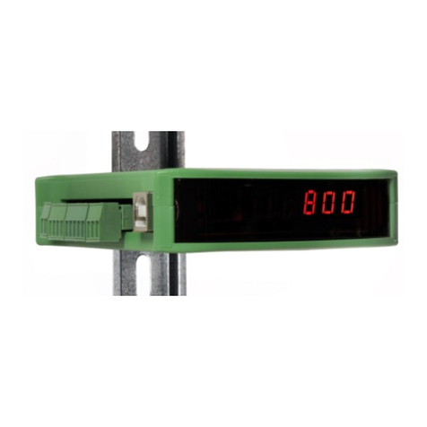
PENKO SGM700 Series User manual

For more information visit
www.penko.com - technical support - literature library
SGM700
PENKO Engineering BV
The Leading Experts In Weighing & Dosing
Digitizer
Manual

SGM700 Digitizer
2
IMPORTANT SAFETY INFORMATION
READ THIS PAGE FIRST!
Penko Engineering manufactures and tests
its products to meet all applicable naonal
and internaonal standards. It is vital that
this instrument is correctly installed, used,
and maintained to ensure it connues to
operate to its opmum specicaon.
The following instrucons must be adhered
to and incorporated into your safety
program when installing, using, and
maintaining Penko products. Failure to
follow the recommended instrucons can
aect the system’s safety and may increase
the risk of serious personal injury, property
damage, damage to this instrument and
may invalidate the product’s warranty.
• Read the instrucons fully prior to
installing, operang, or servicing the
product. If this Instrucon Manual is not the
correct manual for the Penko product you
are using, call 0031(0)318-525630 for a
replacement copy. Keep this Instrucon
Manual in a safe place for future reference.
• If you do not fully understand these
instrucons, contact your Penko
representave for claricaon.
• Pay careful aenon to all warnings,
cauons, and instrucons marked on and
supplied with the product.
• Inform and educate your personnel about
the correct installaon, operaon, and
maintenance procedures for this product.
• Install your equipment as specied in the
installaon instrucons of the appropriate
Instrucon Manual and as per applicable
local and naonal codes. Connect all
products to the proper electrical sources.
• To ensure correct performance, use quali-
ed personnel to install, operate, update,
program, and maintain the product.
• When replacement parts are required,
ensure that qualied technicians use repla-
cement parts specied by Penko. Unauthori-
zed components and procedures can aect
the product's performance and may aect
the connued safe operaon of your
processes. The use of non-specied ‘look-
alike’ substuon parts may result in the
risk of re, electrical hazards, or improper
operaon.
• Ensure that all equipment doors are closed
and protecve covers are in place, except
when maintenance is being performed by
qualied persons, to prevent electrical
shock and personal injury.

SGM700 Digitizer
WARNING
3
ELECTRICAL SHOCK HAZARD
Installing cable connecons and servicing this instrument require access to shock hazard
level voltages which can cause death or serious injury.
Disconnect separate or external power sources to relay contacts before commencing any
maintenance.
The electrical installaon must be carried out in accordance with CE direcons and/or any
other applicable naonal or local codes.
Unused cable conduit entries must be securely sealed by non-ammable blanking plates or
blind grommets to ensure complete enclosure integrity in compliance with personal safety
and environmental protecon requirements.
To ensure safety and correct performance this instrument must be connected to a
properly grounded, three-wire power source.
Proper relay use and conguraon is the responsibility of the user.
Do not operate this instrument without the front cover being secured. Refer any
installaon, operaon or servicing issues to qualied personnel.
WWW.PENKO.COM
Penko is an ETC Company
e-mail: [email protected]

SGM700 Digitizer
4
TABLE OF CONTENT
Chapter Page
1. Loadcell power connection 6
1.1 SGM700 basic digitizer 6
1.2 SGM710 digitizer analog 7
1.3 SGM720 digitizer Ethernet 8
1.4 SGM730 digitizer CAN 9
1.5 SGM740 digitizer Profibus 10
1.6 SGM750 digitizer Serial 11
2.Indication of display 12
3. Explanation of front keys 13
4. First use of Indicator 14
4.1 Configuration menu structure 14
4.2 Weigher Setting 15
4.3 Calibration 17
4.4 First use by using PI Mach II software 21
5. Main Menu 29
5.1 Setpoints (not for SGM710) 29
5.2 TAC (Traceable Acces Code) 30
5.2 CAL (Calibration counter) 31
6. Configuration Menu 32
6.1 Setpoint function settings (not for SGM710) 33
6.2 Setpoint action settings (not for SGM710) 34
6.3 Analog output settings 36
6.4 Local bus communication settings (RS485) 40
6.5 Ethernet settings (SGM720 only) 41
6.6 Can bus port settings (SGM730 only) 47
6.7 Profibus settings (SGM740 only) 50
6.8 RS232 port settings (SGM750 only) 52
6.9 RS422 port settings (SGM750 only) 56
6.10 Indicator settings 60
6.11 Multi range/interval settings 67
6.12 Filter settings 70
6.13 Digital filter settings 74
6.14 Pre-calibration settings 76
6.15 Calibration settings 79
6.16 Theoretic calibration 84

TABLE OF CONTENT
Chapter Page
6.17 Geographic calibration 89
6.18 Date and time configuration (SGM750 only) 92
6.19 Recall 93
6.20 Firmware update 94
7. Firmware update 95
8. Error codes 97
8.1 Weigher error codes 98
10. Profibus protocol description 99
11. Standard factory settings 102
Appendix I 103
Notes 104
SGM700 Digitizer
5

SGM700 Digitizer
1. Load cell / power connection
1.1 SGM700 basic digitizer
6
Analoge output
(option)
Counter inputs
<= 1kHz @
24VDC with
50% duty cycle
Outputs
Max. 35V/0.5A
AC/DC
Local bus
To PC
Config
software
DC POWER
SUPPLY
18-32Vdc
6-Wire load cell
connection
Vexc=5Vdc
When the SGM700 is powered by USB
(not 24Vdc) the loadcell interface and
the analog output don’t work.
This product is intended to be supplied by a Class 2 or
Limited Power Source, rate 18 - 32 Vdc, 0.2A@24Vdc.

SGM700 Digitizer
1. Load cell / power connection
1.2 SGM710 digitizer analog
7
Analoge output
(option)
Local bus
To PC
Config
software
DC POWER
SUPPLY
18-32Vdc
6-Wire load cell
connection
Vexc=5Vdc
When the SGM700 is powered by USB
(not 24Vdc) the loadcell interface and
the analog output don’t work.
This product is intended to be supplied by a Class 2 or
Limited Power Source, rate 18 - 32 Vdc, 0.2A@24Vdc.

SGM700 Digitizer
1. Load cell / power connection
1.3 SGM720 digitizer ethernet
8
Analoge output
(option)
Local bus
To PC
Config
software
DC POWER
SUPPLY
18-32Vdc
6-Wire load cell
connection
Vexc=5Vdc
Counter
inputs <=
1kHz @
24VDC with
50% duty
Ouputs
Max. 35V/0.5A
AC/DC
When the SGM700 is powered by USB
(not 24Vdc) the loadcell interface and
the analog output don’t work.
This product is intended to be supplied by a Class 2 or
Limited Power Source, rate 18 - 32 Vdc, 0.2A@24Vdc.

SGM700 Digitizer
1. Load cell / power connection
1.4 SGM730 digitizer CAN
9
Analoge output
(option)
Local bus
To PC
Config
software
DC POWER
SUPPLY
18-32Vdc
6-Wire load cell
connection
Vexc=5Vdc
Inputs
Input 1=5khz
18-28Vdc
Outputs
Max. 35V/0.5A
AC/DC
Remote
canbus
When the SGM700 is powered by USB
(not 24Vdc) the loadcell interface, the
analog output and CAN bus don’t work.
This product is intended to be supplied by a Class 2 or
Limited Power Source, rate 18 - 32 Vdc, 0.2A@24Vdc.

SGM700 Digitizer
1. Load cell / power connection
1.5 SGM740 digitizer Profibus
10
Analoge output
(option)
Local bus
To PC
Config
software
DC POWER
SUPPLY
18-32Vdc
6-Wire load cell
connection
Vexc=5Vdc
Inputs
Input 1=5khz
18-28Vdc
Outputs
Max. 35V/0.5A
AC/DC
Profibus DP
When the SGM700 is powered by USB
(not 24Vdc) the loadcell interface, the
analog output and Probus don’t work.
This product is intended to be supplied by a Class 2 or
Limited Power Source, rate 18 - 32 Vdc, 0.2A@24Vdc.

SGM700 Digitizer
1. Load cell / power connection
1.6 SGM750 digitizer Serial
11
Analoge output
(option)
Local bus
To PC
Config
software
DC POWER
SUPPLY
18-32Vdc
6-Wire load cell
connection
Vexc=5Vdc
Inputs
Input 1=5khz
18-28Vdc
Outputs
Max. 35V/0.5A
AC/DC
RS232/RS422
When the SGM700 is powered by USB
(not 24Vdc) the loadcell interface, the
analog output and Serial communicaon
don’t work.
This product is intended to be supplied by a Class 2 or
Limited Power Source, rate 18 - 32 Vdc, 0.2A@24Vdc.

SGM700 Digitizer
2. Indication of Display
1. Weigher stable
2. Zero active
3. Tare active
4. Output active 1-4
5. Weigher value
15
2
3
4
1
2
3
With cover closed
With cover opened
Functions of these keys will be described on the next page.
1. key 1 press <2sec.=
key 1 press >2sec.=
2. key 2 press <2sec.=
key 2 press >2sec.=
3. key 2 press <2sec.=
key 2 press >2sec.=
12

SGM700 Digitizer
3. Explanation of front keys
Pressing key 1 “short”.
In Weighing mode: create a new zero level.
In Menu mode: increase value by 1 or move up in menu.
Pressing key 1 “long”.
In Weighing mode: reset zero level to the original zero level.
In Menu mode: decrease value by 1 or move down in menu.
All keys have different functions depending if you are in weighing or
menu mode.
Pressing key 2 “short”.
In Weighing mode: set/ reset tare and reset preset tare.
In Menu mode: go into sub-menu or move cursor 1 position to the left.
Pressing key 2 “long”.
In Weighing mode: set preset tare.
In Menu mode: move cursor 1 position to the right.
Pressing key 3 “short”.
In Weighing mode: enter menu.
In Menu mode: escape move back in menu without saving changes.
Pressing key 3 “long”.
In Weighing mode: enter configuration menu.
In Menu mode: Confirm made changes.
13
Menu will jump back one level every 30 seconds of inactivity.

4. First use of indicator
SGM700 Digitizer
14
4.1 First use of indicator -Configuration menu structure-
- - - Fun setpoint function settings (not for SGM710)
- - - ACn setpoint action settings (not for SGM710)
- - - dAC Analog output settings
- - - 485 Local bus communication settings (RS485)
- - - Eth Ethernet settings (SGM720 only)
- - - CAn Can bus port settings (SGM730 only)
- - - - Pb Profibus settings (SGM740 only)
- - - 232 RS232 port settings (SGM750 only)
- - - 422 RS422 port settings (SGM750 only)
- - - Ind Indicator settings
- - - rng Multi range/interval settings
- - - FIL Filter settings
- - - dSF Digital filter settings
- - - PCL Pre-calibration settings
- - - CAL Calibration settings
- - - tCL Theoretic calibration
- - - gCL Geographic calibration
- - - CLo Date and time configuration (SGM750 only)
- - - rcL Recall
- - - SoF Firmware update

4. First use of indicator
SGM700 Digitizer
Set up the correct indicator setting (step size and decimal point position).
The start
Turn the indicator on by connecting it to the power supply.
Press key 3 for >2
sec. to get in to
Con-
figuration Menu.
(In SGM710)
Go to the Indicator parameters pressing key 1 <2 sec.
Go into the Indicator parameters pressing key 2.
Use Ind 1 to set the maximum net weight value. Set maximum load to prevent
overload by the user. The indicator will not
show any weight above the filled in
value. Range: 0 – full display.
To change the value, press key 2 <2 sec.
Use key 1 and 2 to change the
value. Key 1 is for changing the num-
ber
15
4.2 First use of indicator -Weigher settings-

SGM700 Digitizer
First use of indicator -continue-
When the maximum net weight value is set succesfully, the following screen is
visible:
Dis- play step size
Press key 1 <2 sec. untill you see Ind 5 and press key 2 <2 sec.
Use Ind 5 to set the display step size. The step size
defines the scaled parts of the weight value. The display value will be rounded off
to the nearest value with a valid step size.
Use key 1 to select the correct step size.
Choose between 1, 2, 5, 10, 20, 50, 100, 200, 500 and confirm by pressing key 3
for >2 sec.
Up Down Confirm
Done succesfully, the following screen is visible:
Decimal point
To set the Decimal point position, enter Ind 6 by pressing key 2 <2 sec.
The following screen is visible:
16

SGM700 Digitizer
First use of indicator -continue-
Press key 1 to define the point position and confirm by pressing key 3
for >2 sec.
Left Right Confirm
Done succesfully, the following screen is visible:
Press key 3 <2 sec to go back to Configuration
Menu.
Press key 3 <2 sec to go back to main weigher display.
17

SGM700 Digitizer
First use of indicator -continue-
4.3 First use of indicator -Calibration-
Press key 3 for >2sec. to get in to Configuration Menu.
(In
SGM710)
Go to the Calibration parameters by pressing
key 1 <2 sec. until you see - - - CAL
Check and delete calibration points.
To enter the Calibration settings, press
key 2 <2 sec.
The following screen is visible:
Press key 1 <2 sec. to go to CAL 3
and press key 2 <2 sec.
Use CAL 3 to check and delete all existing calibration points. Step through the cali-
bration points with key 1. Delete a calibration point by
pres- sing
key 3 >3 sec.
18

SGM700 Digitizer
First use of indicator -continue-
Calibration Settings -continue-
When a number is shown, the deletion of one calibration point is completed and
more points need to be deleted. Press key 3 >3 sec to do so.
>3 sec.
When all calibration points are deleted, the following screen is visible:
Entering new calibration points.
Use key 1 <2 sec. to go to CAL 1 and press key 2 <2 sec.
After entering, the following
screen is visible:
And will automatically jump to:
First calibrate the zero point (CP1). Make sure the weigher is unloaded and press
key 3 >2 sec.
19

SGM700 Digitizer
First use of indicator -continue-
Calibration Settings -continue-
The indicator now shows CP2 to calibrate the gain point (CP2).
And will automatically jump to:
Use key 1 and key 2 to enter the reference value. Key 1 is used for changing the
number (1-9), key 2 is used for changing the position of the cursor. Load the
weigher with the reference value and press key 3 >2 sec.
Up Down
Left Right Confirm
Done succesfully the following screen is visible:
Press key 3 <2 sec. to go back to Configuration Menu.
Press key 3 <2 sec. to go back to main weigher display.
20
Other manuals for SGM700 Series
1
This manual suits for next models
5
Table of contents
Other PENKO Measuring Instrument manuals
Popular Measuring Instrument manuals by other brands

Kingst
Kingst LA1016 user guide

Siemens
Siemens 9200 Features guide

PCB Piezotronics
PCB Piezotronics 356A31/NC Installation and operating manual

Opus Technologies
Opus Technologies OP-FSM Installation and user manual

Hanna
Hanna HI 5522 instruction manual

Hanna Instruments
Hanna Instruments HI 96770C instruction manual

ACOEM
ACOEM Fixturlaser SMC BALANCER Quick tips

Topcon
Topcon RL-H1Sa instruction manual

Anritsu
Anritsu MW82119B Guide

PCB Piezotronics
PCB Piezotronics J352B/ACS-23 Installation and operating manual

Hanna Instruments
Hanna Instruments Combo Grochek HI 991404 instruction manual

Fluke
Fluke i430-Flexi-TF-II instruction sheet