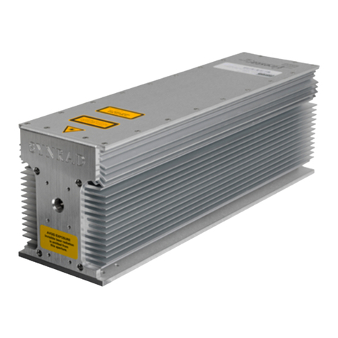
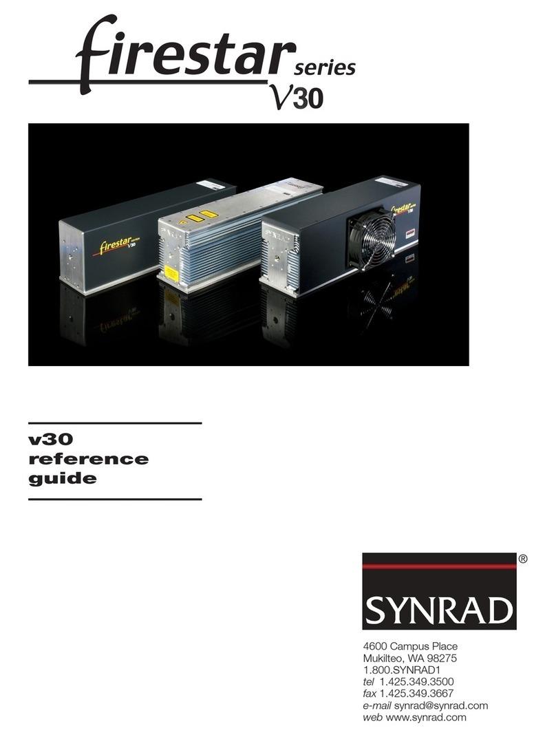
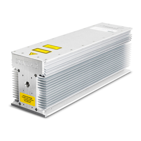
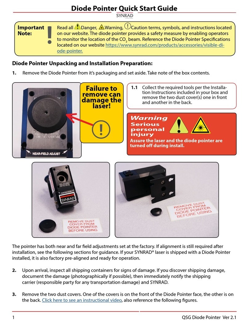
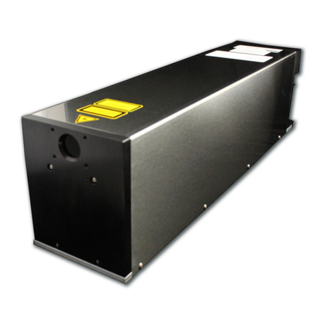
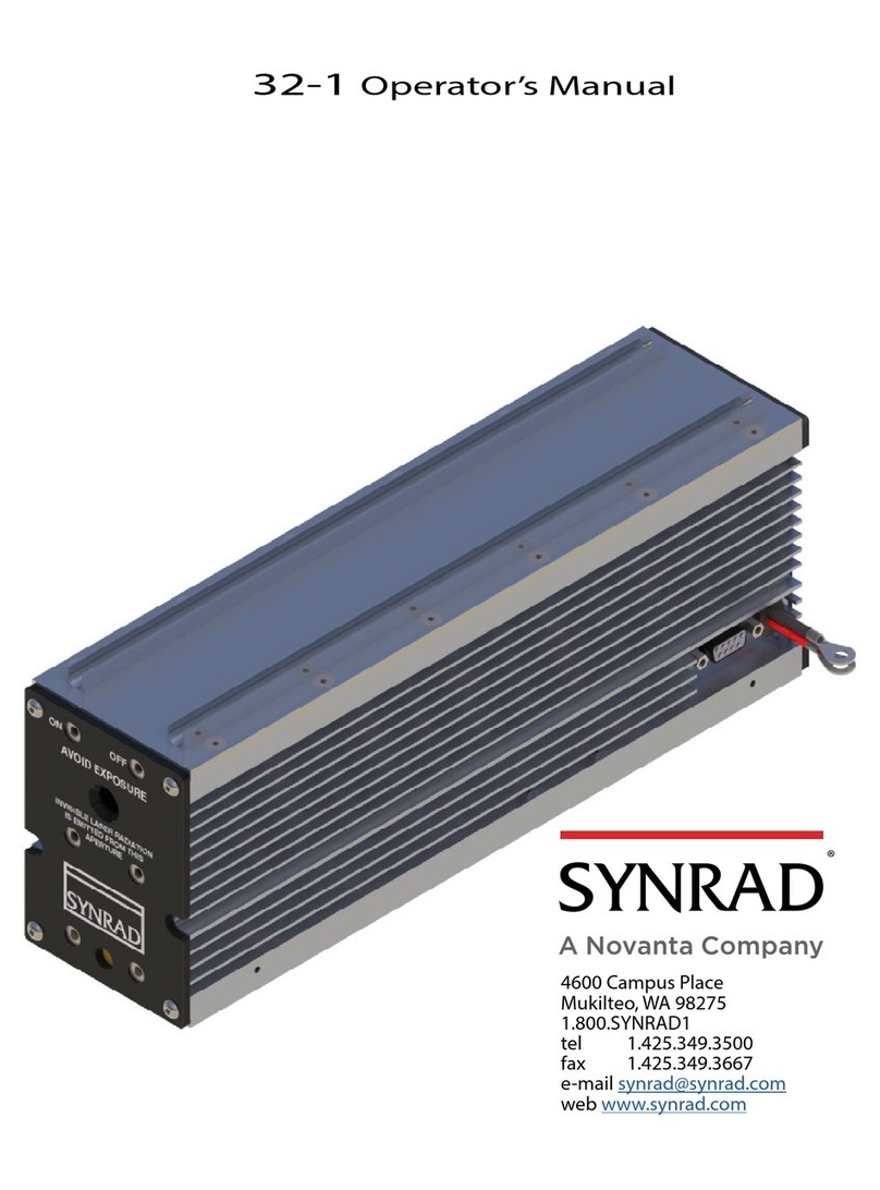
Synrad Firestar OEM vi30 User manual

OEM vi30
reference
guide
4600 Campus Place
Mukilteo, WA 98275 USA
1.800.SYNRAD1
tel 1.425.349.3500
fax 1.425.349.3667
e-mail [email protected]
web www.synrad.com


1
Synrad Firestar OEM vi30 reference guide
Table of Contents
Contents
Warranty information.......................................................2
Trademark/copyright information ....................................2
Laser safety........................................................................3
Terms............................................................................3
General hazards............................................................3
Firestar OEM vi30 label locations ....................................6
Compliance requirements.................................................7
Center for Devices and Radiological Health
(CDRH) requirements.................................................7
Federal Communications Commission
(FCC) requirements.....................................................7
European Union (EU) requirements ...........................8
Declaration of Conformity ...............................................11
Introduction......................................................................12
Inventory...........................................................................12
Ship kit.........................................................................12
Ship kit contents..........................................................12
Installation........................................................................13
Mounting......................................................................13
Cooling.........................................................................15
Electrical connections..................................................15
Control connections ....................................................16
Controls and indicators ....................................................17
Operation..........................................................................18
Status LEDs ..................................................................18
Start-up ........................................................................18
DB-9 I/O connector..........................................................20
Firestar vi30 general specifications ...................................22
Firestar OEM vi30 package outline drawings...................23
Troubleshooting ...............................................................26
Status indications ........................................................26
Laser faults ...................................................................27
DB-9 I/O connector .....................................................28
Optics ...........................................................................28
Figures
Figure 1 Firestar OEM vi30 label locations ...................6
Figure 2 European compliance mark..............................10
Figure 3 Firestar OEM vi30 mounting options..............13
Figure 4 Optional mounting feet installation................14
Figure 5 Recommended vi30 cooling fan locations ........15
Figure 6 Firestar vi30 external temperature monitor-
ing point...........................................................15
Figure 7 Firestar OEM vi30 controls and indicators......17
Figure 8 Firestar OEM vi30 standard package outline
and mounting dimensions................................23
Figure 9 Firestar OEM vi30 package outline and mounting
dimensions – with optional customer-installed
‘Tall’ mounting feet..........................................24
Figure 10 Firestar OEM vi30 package outline and mounting
dimensions – with optional customer-installed
‘Tall/Wide’ mounting feet...................................25
Tables
Table 1 Class IV safety features.....................................9
Table 2 European Union Directives .............................10
Table 3 Ship kit contents..............................................12
Table 4 DB-9 I/O connector pinouts ............................21
Table 5 Firestar OEM vi30 specifications .....................22
Table 6 DB-9 I/O connector status signals ..................26
Firestar OEM vi30 Reference Guide
Version 1.0
Released December 2010
Part number 900-20162-01
4600 Campus Place
Mukilteo, WA 98275 USA
1.800.SYNRAD1
tel 1.425.349.3500
fax 1.425.349.3667
e-mail [email protected]
web www.synrad.com

2Synrad Firestar OEM vi30 reference guide
Warranty information
This is to certify that Firestar®OEM vi30 lasers are guaranteed by SYNRAD, Inc. to be free of all defects in materials and
workmanship for a period of one year from the date of purchase. This warranty does not apply to any defect caused by
negligence, misuse (including environmental factors), accident, alteration, or improper maintenance. We request that you
examine each shipment within 10 days of receipt and inform SYNRAD, Inc. of any shortage or damage. If no discrepancies
are reported, SYNRAD shall assume the shipment was delivered complete and defect-free.
If, within one year from the date of purchase, any part of the Firestar vi30 laser should fail to operate, contact the SYNRAD
Customer Service department at 1.800.SYNRAD1 (outside the U.S. call 1.425.349.3500) and report the problem. When
calling for support, please be prepared to provide the date of purchase, model number and serial number of the unit, and a
brief description of the problem. When returning a unit for service, a Return Authorization (RA) number is required; this
number must be clearly marked on the outside of the shipping container in order for the unit to be properly processed. If
replacement parts are sent to you, then you are required to send the failed parts back to SYNRAD for evaluation unless
otherwise instructed.
If your Firestar vi30 laser fails within the first 45 days after purchase, SYNRAD, Inc. will pay all shipping charges to and
from SYNRAD when shipped as specified by SYNRAD Customer Service. After the first 45 days, SYNRAD will continue
to pay for the costs of shipping the repaired unit or replacement parts back to the customer from SYNRAD. The customer,
however, will be responsible for shipping charges incurred when sending the failed unit or parts back to SYNRAD or a
SYNRAD Authorized Distributor. In order to maintain your product warranty and to ensure the safe and efficient operation
of your Firestar vi30 laser, only authorized SYNRAD replacement parts can be used. This warranty is void if any parts other
than those provided by SYNRAD, Inc. are used.
SYNRAD, Inc. and SYNRAD Authorized Distributors have the sole authority to make warranty statements regarding
SYNRAD products. SYNRAD, Inc. and its Authorized Distributors neither assumes nor authorizes any representative
or other person to assume for us any other warranties in connection with the sale, service, or shipment of our products.
SYNRAD, Inc. reserves the right to make changes and improvements in the design of our products at any time without
incurring any obligation to make equivalent changes in products previously manufactured or shipped. Buyer agrees to hold
SYNRAD harmless from any and all damages, costs, and expenses relating to any claim arising from the design, manufacture,
or use of the product, or arising from a claim that such product furnished Buyer by SYNRAD, or the use thereof, infringes
upon any Patent, foreign or domestic.
Trademark/copyright information
SYNRAD and Firestar are registered trademarks of SYNRAD, Inc.
All other trademarks or registered trademarks are the property of their respective owners.
© 2010 by SYNRAD, Inc.
All rights reserved.

3
Synrad Firestar OEM vi30 reference guide
Laser safety
The Laser safety section includes terms, symbols, and instructions used in this manual or on the equipment to alert operating
and service personnel to the recommended precautions in the care, use, and handling of Class IV laser equipment.
Terms
Certain terms are used throughout this manual or on the equipment labels. Please familiarize yourself with their definitions
and significance.
Imminent hazards which, if not avoided, will result in death or serious injury.
Potential hazards which, if not avoided, could result in death or serious injury.
Potential hazards or unsafe practices which, if not avoided, may result in minor or moderate injury.
Potential hazards or unsafe practices which, if not avoided, may result in product damage.
Important information or recommendations concerning the subject under discussion.
Points of particular interest for more efficient or convenient equipment operation; additional
information or explanation concerning the subject under discussion.
General hazards
Following are descriptions of general hazards and unsafe practices that could result in death, severe injury, or product dam-
age. Specific warnings and cautions not appearing in this section are found throughout the manual.
Danger:
Warning:
Caution:
Note:
Caution:
Danger
serious
personal
injury
This Class IV laser product emits invisible infrared laser radiation in the 10.6 µm CO2
wavelength band.
Do not allow laser radiation to enter the eye by viewing direct or reflected laser energy.
CO2laser radiation can be reflected from metallic objects even though the surface is
darkened. Direct or diffuse laser radiation can inflict severe corneal injuries leading to
permanent eye damage or blindness. All personnel must wear eye protection suitable
for 10.6 µm CO2radiation when in the same area as an exposed laser beam. Eyewear
protects against scattered energy but is not intended to protect against direct viewing
of the beam—never look directly into the laser output aperture or view scattered laser
reflections from metallic surfaces.
Enclose the beam path whenever possible. Exposure to direct or diffuse CO2laser radia-
tion can seriously burn human or animal tissue, which may cause permanent damage.
This product is not intended for use in explosive, or potentially explosive, atmospheres.
serious
personal
injury
Danger
serious
personal
injury
Important Note:

4Synrad Firestar OEM vi30 reference guide
Laser safety (cont.)
Warning
serious
personal
injury
U.S. customers should refer to and follow the laser safety precautions described in the
American National Standards Institute (ANSI) Z136.1-2007 document, Safe Use of
Lasers. Procedures listed in this Standard include the appointment of a Laser Safety Of-
ficer (LSO), operation of the product in an area of limited access by trained personnel,
servicing of equipment only by trained and authorized personnel, and posting of signs
warning of the potential hazards.
European customers should appoint a Laser Safety Officer (LSO) who should refer to
and follow the laser safety precautions described in EN 60825-1, 2007—Safety of Laser
Products.
A risk of exposure to toxic elements, like zinc selenide, may result when certain optical
or beam delivery components are damaged. In the event of damage to laser, marking
head, or beam delivery optics, contact SYNRAD, Inc. or the optics manufacturer for
handling instructions.
serious
personal
injury
Caution
possible
personal
injury
serious
personal
injury
Warning
serious
personal
injury
Materials processing can generate air contaminants such as vapors, fumes, and/or parti-
cles that may be noxious, toxic, or even fatal. Material Safety Data Sheets (MSDS) for
materials being processed should be thoroughly evaluated and the adequacy of provi-
sions for fume extraction, filtering, and venting should be carefully considered. Review
the following references for further information on exposure criteria:
ANSI Z136.1-2007, Safe Use of Lasers, section 7.3.
U.S. Government’s Code of Federal Regulations: 29 CFR 1910, Subpart Z.
Threshold Limit Values (TLV’s) published by the American Conference of Governmen-
tal Industrial Hygienists (ACGIH).
It may be necessary to consult with local governmental agencies regarding restrictions
on the venting of processing vapors.
serious
personal
injury
Warning
serious
personal
injury
Use of controls or adjustments or performance of procedures other than those specified
herein may result in hazardous radiation exposure.

5
Synrad Firestar OEM vi30 reference guide
Laser safety (cont.)
Firestar®OEM vi30 lasers should be installed and operated in manufacturing or laboratory facilities by trained personnel
only. Due to the considerable risks and hazards associated with the installation and operational use of any equipment incor-
porating a laser, the operator must follow product warning labels and instructions to the user regarding laser safety.
To prevent exposure to direct or scattered laser radiation, follow all safety precautions specified throughout this manual and
exercise safe operating practices per ANSI Z136.1-2007 at all times when actively lasing.
Always wear safety glasses or protective goggles with side shields to reduce the risk of damage to the eyes when operating the
laser.
A CO2laser is an intense heat source and will ignite most non-metallic materials under the proper conditions. Never oper-
ate the laser in the presence of flammable or explosive materials, gases, liquids, or vapors.
The use of controls or adjustments or performance of procedures other than those specified herein may result in exposure to
hazardous invisible laser radiation, damage to, or malfunction of the laser. Severe burns will result from exposure to the laser
beam.
Safe operation of the laser requires the use of an external beam block to safely block the beam from traveling beyond the
desired work area. Do not place your body or any combustible object in the path of the laser beam. Use a water-cooled beam
dump or power meter, or similar non-scattering, noncombustible material as the beam block. Never use organic material or
metals as the beam blocker; organic materials, in general, are apt to combust or melt and metals act as specular reflectors
which may create a serious hazard outside the immediate work area.
Other hazards
The following hazards would be typical for this product family when incorporated for intended use: (A) risk of injury when
lifting or moving the unit; (B) risk of exposure to hazardous laser energy through unauthorized removal of access panels,
doors, or protective barriers; (C) risk of exposure to hazardous laser energy and injury due to failure of personnel to use
proper eye protection and/or failure to adhere to applicable laser safety procedures; (D) risk of exposure to hazardous or le-
thal voltages through unauthorized removal of covers, doors, or access panels; (E) generation of hazardous air contaminants
that may be noxious, toxic, or even fatal.
Disposal
This product contains components that are considered hazardous industrial waste. If a situation occurs where the laser is
rendered non-functional and cannot be repaired, it may be returned to SYNRAD, Inc. who, for a fee, will ensure adequate
disassembly, recycling, and/or disposal of the product.
Additional laser safety information
The SYNRAD web site (http://www.synrad.com/LaserFacts/lasersafety.html) contains an online laser safety handbook that
provides information on (1) Laser Safety Standards for Firestar’s/System Integrators including product classification, prod-
uct housing, product features, and other CDRH requirements; (2) Laser Safety Standards for End Users including Class I
installations, Class IV installations, laser hazards, ANSI Standard, U.S. State requirements, and OSHA; (3) References and
Sources including CDRH, ANSI/OSHA; and (4) Assistance with Requirements.
In addition, the Occupational Safety and Health Administration (OSHA) provides an online Technical Manual (located at
http://www.osha.gov/dts/osta/otm/otm_iii/otm_iii_6.html). Section III, Chapter 6 and Appendix III are good resources for
laser safety information.
Another excellent laser safety resource is the Laser Institute of America (LIA). Their comprehensive web site is located at
http://www.laserinstitute.org.

6Synrad Firestar OEM vi30 reference guide
Firestar OEM vi30 label locations
Figure 1 Firestar OEM vi30 label locations
Front
Top
Bottom
This laser product is manufactured under
one or more of the following U.S. Patents:
4,805,182 5,065,405 6,195,379 6,603,794
4,837,772 5,215,864 6,198,758 6,614,826
5,008,894 5,602,865 6,198,759
Other U.S. and International Patents pending.
INVISIBLE LASER RADIATION
AVOID EYE OR SKIN EXPOSURE TO
DIRECT OR SCATTERED RADIATION
CLASS 4 LASER PRODUCT
EN-60825-1, 2007
75 WATTS MAX
10200-10800 nm
INVISIBLELASER RADIATION
AVOIDEYE OR SKIN EXPOSURE TO
DIRECTOR SCATTEREDRADIAT ION
CLASS4 LASER PRODUCT
AVOID EXPOSURE
Invisible laser radiation
is emitted from
this aperture.
AVOID EXPOSURE
Invisible laser radiation
is emitted from
this aperture.
Thislaser product is manufa cturedunder
oneor more of the fo llowingU. S.Patents:
4,805,182 5,065,405 6,195,379 6,603,794
4,837,772 5,215,864 6,198,758 6,614,826
5,008,894 5,602,865 6,198,759
OtherU. S.andInternational Patents pending.
MODEL #: FSVi30SA
SERIAL #: i030127100123
TESTED AT: 30V MFG: May 07, 2010
This laser component does not comply with standards for complete
laser products as specified by 21 CFR 1040.10 or IEC 60825-1.
SYNRAD, Inc. 4600 Campus Place, Mukilteo WA 98275 425.349.3500
EN-60825-1,2007
75WATTS MAX
10200-10800nm
MODEL#: FSVi30SA
SERIAL#: i030127100123
TESTEDAT: 30V MFG: May07, 2010
Thislaser component does not comply with standards for complete
laserproducts as specified by 21 CFR 1040.10 or IEC 60825-1.
SYNRAD,Inc. 4600 Campus Place, Mukilteo WA 98275 425.349.3500

7
Synrad Firestar OEM vi30 reference guide
Compliance requirements
SYNRAD lasers are designed, tested, and certified to comply with certain United States (U.S.) and European Union (EU)
regulations. These regulations impose product performance requirements related to electromagnetic compatibility (EMC)
and product safety characteristics for industrial, scientific, and medical (ISM) equipment. The specific provisions to which
systems containing Firestar OEM vi30 lasers must comply are identified and described in the following paragraphs.
In the U.S., laser safety requirements are governed by the Center for Devices and Radiological Health (CDRH) under the
auspices of the U.S. Food and Drug Administration (FDA) while radiated emission standards fall under the jurisdiction of
the U.S. Federal Communications Commission (FCC). Outside the U.S., laser safety and emissions are governed by Euro-
pean Union (EU) Directives and Standards.
In the matter of CE-compliant laser products, SYNRAD, Inc. assumes no responsibility for the compliance of the system
into which the product is integrated, other than to supply and/or recommend laser components that are CE marked for com-
pliance with applicable European Union Directives.
Because OEM laser products are intended for incorporation as components in a laser processing system, they do not meet
all of the Standards for complete laser processing systems as specified by 21 CFR, Part 1040 or EN 60825-1. SYNRAD, Inc.
assumes no responsibility for the compliance of the system into which OEM laser products are integrated.
Center for Devices and Radiological Health
(CDRH) requirements
Firestar vi30 lasers are OEM products intended for incorporation as components in laser processing systems. As supplied by
SYNRAD, these lasers do not meet the requirements of 21 CFR, Subchapter J without additional safeguards. In the U.S.,
the Buyer of these OEM laser components is solely responsible for the assurance that the laser processing system sold to an
end user complies with all laser safety requirements before the actual sale of the system. Under CDRH regulations, the Buyer
must submit a report to the CDRH prior to shipping the system. In jurisdictions outside the U.S., it is the sole responsibility
of the Buyer of these OEM components to ensure that they meet all applicable local laser safety requirements. In cases where
the Buyer is also the end-user of the OEM laser product, the Buyer/end-user must integrate the laser so that it complies with
all applicable laser safety standards as set forth above.
To aid in the development of integrated OEM vi30 systems see Table 1, Class IV safety features. The table indicates which
features are available on vi30 OEM lasers, the type and description of the feature, and if the feature is required by CDRH
regulations.
Federal Communications Commission
(FCC) requirements
The United States Communication Act of 1934 vested the Federal Communications Commission (FCC) with the author-
ity to regulate equipment that emits electromagnetic radiation in the radio frequency spectrum. The purpose of the Com-
munication Act was to prevent harmful electromagnetic interference (EMI) from affecting authorized radio communication
services. The FCC regulations that govern industrial, scientific, and medical (ISM) equipment are fully described in 47 CFR,
Part 18, Subpart C.
SYNRAD’s Firestar vi30 OEM lasers have been tested and found to comply by demonstrating performance characteristics
that have met or exceeded the requirements of 47 CFR, Part 18, Radiated and Conducted Emissions.
FCC information to the user
NOTE: The following information to the user is provided to comply with the requirements of 47 CFR, Part 18, Section 213.
Interference Potential
In our testing, SYNRAD, Inc. has not discovered any significant electrical interference traceable to Firestar
OEM vi30 lasers.

8Synrad Firestar OEM vi30 reference guide
Compliance requirements (cont.)
System Maintenance
Ensure that all exterior covers are properly fastened in position.
Measures to Correct Interference
If you suspect that your Firestar OEM vi30 laser interferes with other equipment, take the following steps to
minimize this interference:
1
Use shielded cables to and from the equipment that is experiencing interference problems.
2
Ensure that the vi30 laser is properly grounded to the same electrical potential as the equipment or system
it is connected to.
FCC caution to the user
The Federal Communications Commission warns the user that changes or modifications of the unit not expressly approved
by the party responsible for compliance could void the user’s authority to operate the equipment.
European Union (EU) requirements
RoHS compliance
SYNRAD Firestar OEM vi30 lasers meet the requirements of the European Parliament and Council Directive 2002/95/EC
on the Restriction of the Use of Certain Hazardous Substances in Electrical and Electronic Equipment, as amended by Deci-
sion 2005/618/EC establishing maximum concentration values for certain hazardous substances in electrical and electronic
equipment.
Laser safety standards
Under the Low Voltage Directive, 2006/95/EC, the European Norm document 60825-1 was developed to protect persons
from laser radiation by imposing requirements upon manufacturers of laser products to provide an indication of laser radia-
tion; to classify laser products according to the degree of hazard; to require both user and manufacturer to establish proce-
dures so that proper precautions are adopted; to ensure adequate warning of the hazards associated with accessible radiation
through signs, labels, and instructions; to improve control of laser radiation through protective features; and to provide safe
usage of laser products by specifying user control measures.
SYNRAD’s Firestar vi30 lasers are OEM products intended for incorporation as components in laser processing systems. As
supplied by SYNRAD, these lasers do not meet the requirements of EN 60825-1 without additional safeguards. European
Union Directives state that “OEM laser products which are sold to other manufacturers for use as components of any system
for subsequent sale are not subject to this Standard, since the final product will itself be subject to the Standard.” This
means that Buyers of OEM laser components are solely responsible for the assurance that the laser processing system sold to
an end-user complies with all laser safety requirements before the actual sale of the system. Note that when an OEM laser
component is incorporated into another device or system, the entire machinery installation may be required to conform to
EN 60825-1, 60204-1, Safety of Machinery; the Machinery Directive EN 98/37/EC; and/or any other applicable Standards.
In cases where the Buyer is also the end-user of the OEM laser product, the Buyer/end-user must integrate the laser so that it
complies with all applicable laser safety standards as set forth above.
To aid in the development of integrated vi30 systems see Table 1, Class IV safety features. The table indicates which features
are available on Firestar vi30 OEM lasers, the type and description of the feature, and if the feature is required by CDRH
regulations.

9
Synrad Firestar OEM vi30 reference guide
Compliance requirements (cont.)
Table 1 Class IV safety features
Required by: Provided on
Feature Location/Description CDRH EN60825-1 Firestar vi30
Keyswitch Rear panel control Yes Yes No
On/Off/Reset Keyswitch controls power to laser electronics.
Key cannot be removed from switch in the “On” position.
Shutter Laser control Yes Yes No
function Functions as a beam attenuator to disable RF driver/laser output
when closed.
PWR (Power) Rear panel indicator (Green) No No Yes
indicator Illuminates green to indicate DC power is applied.
RDY (Ready) Rear panel indicator (Yellow) Yes Yes Yes
indicator Indicates that laser has power applied and is capable of lasing.
LASE Rear panel indicator (Red) Yes Yes Yes
indicator Indicates that Firestar is actively lasing. LASE LED illuminates
when the duty cycle of the Command signal is long enough to
produce laser output.
Five second Firestar circuit element Yes No Yes
delay Disables RF driver/laser output for five seconds after Laser Enable
signal is applied.
Power fail Firestar circuit element Yes Yes No
lockout Disables RF driver/laser output if input power is removed then later
reapplied (AC power failure or remote interlock actuation) while
Keyswitch is in “On” position.
Remote Rear panel connection Yes Yes No
Interlock Disables RF driver/laser output when a remote interlock switch on
an equipment door or panel is opened.
Over Firestar circuit element No No Yes
temperature Temperature shutdown occurs if temperature of the laser tube
protection rises above safe operating limits.
Warning Firestar exterior Yes Yes Yes
labels Labels attached to various external housing locations to
warn personnel of potential laser hazards.
Electromagnetic interference standards
The European Union’s Electromagnetic Compatibility (EMC) Directive, 2004/108/EC, is the sole Directive developed to
address electromagnetic interference (EMI) issues in electronic equipment. In particular, the Directive calls out European
Norm (EN) documents that define the emission and immunity standards for specific product categories. For Firestar vi30 la-
sers, CISPR:11 and EN 61000-6-4 define radiated and conducted RF emission limits while the generic Standard EN 61000-
6-2 defines immunity requirements.
SYNRAD’s Firestar OEM vi30 lasers have been tested and found to comply by demonstrating performance characteristics
that have met or exceeded the requirements of EMC Directive 2004/108/EC.

10 Synrad Firestar OEM vi30 reference guide
Compliance requirements (cont.)
When integrating SYNRAD’s OEM vi30 lasers, the Buyer and/or integrator of the end system is responsible for meeting all
applicable Standards to obtain the CE mark. To aid this compliance process, SYNRAD’s testing program has demonstrated
that Firestar vi30 lasers comply with the relevant requirements of 2004/108/EC, the Electromagnetic Compatibility Direc-
tive, as summarized in Table 2 below.
Table 2 European Union Directives
Applicable Standards/Norms
2004/108/EC Electromagnetic Compatibility
2006/95/EC Low Voltage Directive
2002/95/EC RoHS Directive (amended 2005/618/EC)
EN 61010-1:2001 Safety Requirements for Electrical Equipment for Measurement, Control, and
Laboratory Use - Part 1:General Requirements
CISPR 11:2009 Conducted and Radiated Emissions, Group 1, Class A
EN 61000-6-4 (2007) Emission Standard for Industrial Environments
EN 61000-6-2 (2005) Immunity for Industrial Environments
EN 61000-4-2:1995 +A1:1998 +A2:2001 Electrostatic Discharge
EN 61000-4-3:2006 +A1:2008 Radiated RF Immunity
EN 61000-4-4:2004 +C1:2006 +C2:2007 Electrical Fast Transient/Burst
EN 61000-4-5:2006 Surge Immunity
EN 61000-4-6:2009 Conducted RF Immunity
EN 61000-4-8:1994 +A1:2000 Power Frequency H-Field Immunity
After a product has met the requirements of all applicable EU Directives, the product can bear the official compliance mark
of the European Union as shown in Figure 2.
Figure 2 European compliance mark

11
Synrad Firestar OEM vi30 reference guide
Declaration of Conformity
in accordance with ISO/IEC 17050-2:2004
We,
Manufacturer’s Name: SYNRAD, Inc.
Manufacturer’s Address: 4600 Campus Place
Mukilteo, WA 98275
U.S.A.
hereby declare under our sole responsibility that the following equipment:
Product Name: Firestar OEM vi30 Laser*
Model Number: FSVi30SAB
conforms to the following Directive(s) and Standard(s):
Applicable Directive(s): 2004/108/EC Electromagnetic Compatibility Directive
2002/95/EC RoHS Directive (amended by 2005/618/EC)
Applicable Standard(s):
*OEM lasers do not comply with EN 60825-1:2007, Safety of Laser Products. Buyers of OEM laser products are solely responsible
for meeting applicable Directives and Standards for CE compliance and marking.
Corporate Officer: European Contact:
Dave Clarke, President of SYNRAD, Inc.
Dated 3 December 2010
Excel Technology Europe GmbH
Münchner Str. 2a
D-82152 Planegg
Germany
EN 61010-1:2001 Safety Requirements for Electrical Equipment for
Measurement, Control, and Laboratory Use - Part 1
CISPR 11:2009 Conducted and Radiated Emissions, Group 1, Class A
EN 61000-6-4 (2007) Emission Standard for Industrial Environments
EN 61000-6-2 (2005) Immunity for Industrial Environments
EN 61000-4-2:1995 +A1:1998 +A2:2001 Electrostatic Discharge
EN 61000-4-3:2006 +A1:2008 Radiated RF Immunity
EN 61000-4-4:2004 +C1:2006 +C2:2007 Electrical Fast Transient/Burst
EN 61000-4-5:2006 Surge Immunity
EN 61000-4-6:2009 Conducted RF Immunity
EN 61000-4-8:1994 +A1:2000 Power Frequency H-Field Immunity

12 Synrad Firestar OEM vi30 reference guide
Introduction
The Firestar OEM vi30 laser is a more compact version of the Firestar v30 laser and is designed to provide OEMs with the
smallest possible 30 W laser package. The optoisolated PWM input, PWM Positive, (on the DB-9 I/O connector) is identical
to that on the v30 laser and, like the v30, the vi30 does not incorporate a built-in tickle generator—users must provide a 5
kHz, 1 µs tickle pulse between applied PWM signals. All input/output signals on the vi30’s DB-9 I/O connector are identical
to v30 I/O signals and operate at the same 5V logic levels to ensure compatibility and ease of installation when retrofitting
the vi30 into existing v30 laser systems. The vi30 user interface consists of only the DB-9 I/O connector, it does not include
an RJ45 connection.
Note: Although the OEM vi30 is part of the Firestar family of lasers, its user interface differs significantly from the stan-
dard Firestar interface design. See the DB-9 I/O connector section for details.
In addition to the standard vi30 mounting method (see Figure 8, Firestar OEM vi30 standard package outline and mounting di-
mensions), there are two optional vi30 mounting kits available separately from the factory. The feet in the ‘Tall’ mounting kit
(Synrad P/N 250-20190-01) raise the OEM vi30 by 0.231" (5.9 mm) to match the v30’s beam exit height without extending
beyond the standard vi30 baseplate. The ‘Tall/Wide’ mounting kit (Synrad P/N 250-20190-02) raises the vi30 to match v30
beam exit height and the wider feet allow the vi30 to be installed using existing v30 mounting holes.
The OEM vi30 laser is available in an air-cooled (SA) configuration only, so the OEM or end-user is required to supply ap-
propriate means of cooling the laser.
The Firestar OEM vi30 laser is an OEM product intended for incorporation as a component in a laser processing system and
as such does not comply with 21 CFR, Subchapter J or EN 60825-1 without additional safeguards.
Inventory
Ship kit
Table 3 lists items included in the OEM vi30 ship kit.
Table 3 Ship kit contents
Shipping Box Contents Qty Shipping Box Contents Qty
SYNRAD Firestar OEM vi30 Laser...............1 Spare Fuse ..................................................... 1
Mounting Bolts ..............................................3 Final Test Report .......................................... 1
Firestar OEM vi30 Reference Guide .............1
Ship kit contents
Each item listed in Table 2 is described below:
SYNRAD Firestar OEM vi30 Laser – for cutting, welding, drilling, and marking a wide variety of products.
Mounting Bolts – 1/4–20 UNC bolts fasten the laser to your mounting surface.
Firestar OEM vi30 Reference Guide – provides setup, operation, and maintenance information for your vi30 laser.
Spare Fuse – fast-blow 15 A fuse protects the Firestar vi30’s internal circuitry.
Final Test Report – contains data collected during the laser’s final pre-shipment test.

13
Synrad Firestar OEM vi30 reference guide
Installation
Mounting
The Firestar OEM vi30 base plate (and the optional customer-installed mounting feet) are designed so the laser can be easily
mounted using only three 1/4–20 UNC or M6×1 ISO fasteners. Three ball bearing ‘feet’ eliminate any possible distortion of
the laser tube caused by variations in the flatness of the mounting surface.
Important Note: To prevent possible distortion of the laser tube, you must fasten the vi30 laser directly to your mount-
ing surface through the base plate or the optional factory-designed mounting feet. Both the vi30 base
plate and the optional ‘Tall’ or ‘Tall/Wide’ feet incorporate a hardened ball bearing design that elimi-
nates any possible distortion caused by variations in the flatness of the mounting surface
Installing the optional mounting feet
For most customers, the standard baseplate design provides the smallest physical footprint for mounting the OEM vi30 in
compact laser systems. Where Firestar v30 compatibility is desired, you can install one of the two optional mounting kits
(available separately from the factory). The ‘Tall’ mounting kit (Synrad P/N 250-20190-01) raises the vi30 laser by 0.231"
(5.9 mm) to match v30 beam exit height. Feet in the ‘Tall/Wide’ mounting kit (Synrad P/N 250-20190-02) raise the vi30 to
match v30 beam exit height and mounting dimensions exactly. All three mounting options are shown in Figure 3 below. For
dimensional information, see the Firestar vi30 outline and mounting drawings later in this manual.
Figure 3 Firestar OEM vi30 mounting options
To attach the optional ‘Tall’ or ‘Tall/Wide’ mounting feet to your OEM vi30 laser, refer to Figure 4 and perform the following
steps:
1
Carefully place the OEM vi30 laser upside down on the work surface.
Standard vi30 Baseplate
(Smallest Footprint)
‘Tall’ Mounting Feet
(Matches v30 Beam Exit Height)
‘Tall/Wide’ Mounting Feet
(Matches v30 Beam Exit & Mounting)

14 Synrad Firestar OEM vi30 reference guide
Installation (cont.)
2
Orient the ‘Tall’ or ‘Tall/Wide’ mounting feet so the ball bearings are facing up and position them over the existing
ball bearings/mounting holes in the laser baseplate.
3
Locate the M4×.7 ISO Allen cap screw fasteners in the mounting kit and insert them through the mounting feet into
the threaded holes of the vi30 baseplate. Turn the screws by hand until the threads engage.
4
Evenly tighten all four cap screws to a torque value between 18–26 in lbf(2–3 N m).
Bottom View
Front
Fasten Feet Using Screws From Mounting Kit
Position Optional Feet Over Baseplate
Figure 4 Optional mounting feet installation
Mounting the OEM vi30 laser
To fasten the Firestar OEM vi30 laser to your mounting surface, perform the following steps:
1
Refer to the appropriate vi30 outline and mounting diagram and drill three holes into your mounting surface that cor-
respond to either the UNC or metric baseplate (or optional mounting foot) hole pattern.
2
Place the vi30 on the mounting surface so that the threaded holes on the baseplate (or optional mounting feet) line up
with the holes in your mounting surface.
Note: Mounting bolts must not extend further than 0.24" (6.0 mm) into the vi30 baseplate or into the optional vi30
mounting feet.
3
Insert three 1/4–20 UNC or M6×1 ISO Allen cap screws through the mounting surface into the threaded holes of the
vi30 baseplate (or mounting feet). Turn the screws by hand until the threads engage.
4
Evenly tighten all three cap screws to a maximum torque value of 6 ft lbf(8 N m).

15
Synrad Firestar OEM vi30 reference guide
Installation (cont.)
Cooling
Cooling fan configuration
Because Firestar vi30 lasers are OEM models, they do not include cooling fans. To prevent an over temperature fault from
occurring, customers must provide two 140 CFM cooling fans and mount them symmetrically as shown in Figure 5. Cool-
ing fans should have a diameter of approximately 4–5" (102 – 127 mm) and have at least 2.25" (57.2 mm) of unobstructed
clearance between the rear face of the fan housing and any mounting surface or enclosure. Position both fans so the front
face is within 3.0" (76 mm) of the vi30's cooling fins. When retrofitting an OEM vi30 into an existing v30 laser system, the
original cooling method (fans and/or fan shroud) can be used provided the fans are within 3.0" (76 mm) of the vi30 chassis.
Like Firestar v30 lasers, the OEM vi30 does not provide a voltage output sufficient to power cooling fans; customers must
provide an external power source to drive the selected cooling fans. Because of the heat generated by internal RF circuitry,
establishing significant airflow evenly over the entire surface of the combined laser/RF chassis is vitally important to the
performance and longevity of the laser.
Figure 5 Recommended vi30 cooling fan locations
Temperature monitoring
For customers who wish to monitor vi30 chassis temperature, Figure 6 shows the recommended location for mounting a
customer-supplied, external temperature sensor. A reading of approximately 60 °C (140 °F) at this location is the point
where over temperature faults will begin to occur.
Gap Between Fan and Laser
Must Be Less Than 3.0” (76 mm)
Figure 6 Firestar vi30 external temperature monitoring point
Top View
Front Measure chassis temperature
at this location

16 Synrad Firestar OEM vi30 reference guide
Installation (cont.)
Electrical connections
DC power supply
The Firestar OEM vi30 laser requires a DC power supply capable of providing 48 VDC at 10 A minimum (11 A peak for less
than 1 ms). To connect the vi30 laser to the 48 VDC power supply, perform the following steps:
1
Verify that input AC power to the DC power supply is physically locked out or disconnected.
2
Locate the 48 VDC output terminals on the power supply’s output section and connect the black (–) DC power cable
from the vi30 laser to the negative (–) output terminal.
3
Connect the red (+) DC power cable from the laser to the positive (+) 48 VDC output terminal.
Note: The negative (–) side of the DC input to the laser is internally connected so that the laser chassis serves as DC
power ground. You should isolate the laser’s DC power supply so that the only grounded connection is at the laser.
Alternatively, you can mount the laser chassis on an insulating pad or film in order to electrically isolate the laser
when other equipment is grounded to the laser’s DC power supply.
Control connections
Complete all control connections to the Firestar OEM vi30 laser through the DB-9 I/O connector on the vi30’s rear panel.
The interface connector receives tickle pulse and PWM Command signals and also serves as the connection point for auxil-
iary signals between the laser and any parts handling, automation, or monitoring equipment. Refer to the DB-9 I/O connector
section for specific details about the Firestar vi30 user interface.
The Firestar vi30 control board does not incorporate a built-in tickle generator. If you are not using a SYNRAD UC-2000
Universal Laser Controller to operate the laser, you must provide a 5 kHz, 1 µs tickle pulse between applied PWM signals.
Refer to the Firestar v40 Operator’s Manual and see Controlling laser power in the Technical Reference chapter for tickle signal
descriptions. A PDF version is available from our web site at: http://www.synrad.com/Products/manuals.htm.
Warning
serious
personal
injury
Always use shielded cable when connecting your PWM Command signal source to the
PWM Positive/PWM Negative connections. In electrically-noisy environments, long
lengths of unshielded wire act like an antenna and may generate enough voltage to
trigger uncommanded lasing.

17
Synrad Firestar OEM vi30 reference guide
Controls and indicators
Figure 7 Firestar OEM vi30 controls and indicators
1
Aperture Seal – prevents dust from damaging the output coupler during shipping. Remove the red self-adhesive label
before applying power to the laser.
2
Laser Aperture – provides an opening in the OEM vi30’s front panel from which the beam exits.
3
Optical Accessories Mounting – provides six threaded holes (8–32 UNC) for mounting optional beam delivery com-
ponents available from SYNRAD. Because excessive weight may damage the laser, consult SYNRAD before mounting
components not specifically designed as Firestar options. Refer to the Firestar OEM vi30 package outline drawings for
mounting hole dimensions.
Note: When mounting optical components to the Firestar vi30, excessive fastener length may damage the laser. See the
package outline drawings for important information about accessory mounting hole depth.
4
DC Power Cables – receives 48 VDC from the DC power supply. The cables are manufactured with #12 AWG wire
and measure 1 meter (40 inches) in length. The red (positive) cable contains a replaceable in-line fuse. If fuse replace-
ment is required, replace it with a Bussman ABC15 or a Littelfuse 314015 fuse.
5
DB-9 I/O Connector – provides a connection point for auxiliary output power as well as input and output signals.
Refer to the DB-9 I/O connector section for DB-9 interface details and pinouts.
6
LASE Indicator – illuminates red to indicate that the Firestar vi30 is actively lasing. The LASE indicator is off when
tickle pulses are being generated and illuminates red when PWM Command signal pulses are long enough to produce
laser output.
7
RDY Indicator – illuminates yellow when the laser is enabled, indicating that lasing will begin when a Command
signal is applied.
8
PWR Indicator – illuminates green when +48 VDC power is applied to the laser.
3
2
1
AVOID EXPOSURE
Invisible laser radiation
is emitted from
this aperture.
4
7
8
6
LASE
RDY
PWR
I/O INTERFACE
5

18 Synrad Firestar OEM vi30 reference guide
Operation
Status LEDs
Three status LEDs provide a visual indication of operating status. A green PWR LED illuminates when DC power is applied
to the laser. The yellow RDY LED indicates that a Laser Enable signal has been applied and that, after a five-second delay,
lasing will begin once a PWM Command signal is received. The LASE LED illuminates red to indicate that the PWM signal
is sufficient to induce laser output.
Start-up
Danger
serious
personal
injury
This Class IV laser emits invisible infrared laser radiation in the 10.6 µm CO2wave-
length band. Since direct or diffuse laser radiation can inflict severe corneal injuries,
always wear eye protection when in the same area as an exposed laser beam. Do not al-
low the laser beam to contact a person. This product emits an invisible laser beam that
is capable of seriously burning human tissue.
Always be aware of the beam’s path and always use a beam block while testing.
Warning
serious
personal
injury
On Firestar OEM vi30 lasers, DC voltage faults are not latched. Clearing a DC voltage
fault (under- or over-voltage) will restore normal operation and lasing is possible after
the five-second delay provided that the Laser Enable input signal is high. Because
exposure to 10.6 µm CO2laser radiation can inflict severe corneal injuries and seri-
ously burn human tissue, the Firestar or System Integrator must ensure that appropriate
safeguards are in place to prevent unintended lasing.
Note: After applying 48 VDC, but before operating the laser, you must provide a Laser Enable signal to the DB-9 I/O con-
nector.
1
If you have not already done so, remove the red self-adhesive aperture seal from the front of the laser.
2
Ensure that all personnel in the area are wearing protective eyewear.
3
Place a beam block 24 inches from the laser aperture to prevent the beam from traveling beyond the work area.
Note: If you are using a UC-2000 to control the OEM vi30 laser, refer to the UC-2000 Laser Controller Operator’s Manual
for setup and operation instructions before continuing.
If you are not using a UC-2000 to control the laser, you must provide tickle and PWM Command signals to control
power output. Refer to the Firestar v40 Operator’s Manual and see Controlling laser power in the Technical Reference
chapter for tickle and PWM Command signal descriptions. A PDF version is available from our web site at http://
www.synrad.com/Products/manuals.htm.
4
Set the UC-2000 to MANUAL mode, and then set the PWM Adj Knob to provide zero percent output (0.0%). The
UC-2000’s Lase indicator should be Off.
If not using a UC-2000, ensure that your PWM controller is set to zero percent output (0.0%).
This manual suits for next models
1
Table of contents
Other Synrad Measuring Instrument manuals

Synrad
Synrad Pulstar P100 Series User manual

Synrad
Synrad Firestar f series User manual

Synrad
Synrad Novanta 48 Series User manual

Synrad
Synrad Diode Pointer User manual

Synrad
Synrad Firestar i401 Series User manual

Synrad
Synrad Novanta 48 Series User manual

Synrad
Synrad Firestar f201 User manual

Synrad
Synrad 32-1 User manual

Synrad
Synrad Firestar V30 User manual

Synrad
Synrad Firestar TI Series User manual