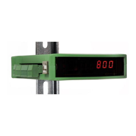
PENKO 1020 FMD User manual

1020 FMD
1
PENKO Engineering B.V.
Your Partner for Fully Engineered Factory Solutions
Manual:
1020 FMD

1020 FMD
2
IMPORTANT SAFETY INFORMATION
READ THIS PAGE FIRST!
PENKO Engineering B.V. manufactures and
tests its products to meet all applicable
national and international standards. It is
vital that this instrument is correctly
installed, used, and maintained to ensure it
continues to operate to its optimum
specification.
The following instructions must be adhered
to and incorporated into your safety
program when installing, using, and
maintaining PENKO products. Failure to
follow the recommended instructions can
affect the system’s safety and may increase
the risk of serious personal injury, property
damage, damage to this instrument and
may invalidate the product’s warranty.
• Read the instructions fully prior to
installing, operating, or servicing the
product. If this Instruction Manual is not
the correct manual for the PENKO product
you are using, call 0031(0)318-525630 for a
replacement copy. Keep this Instruction
Manual in a safe place for future reference.
• If you do not fully understand these
instructions, contact your PENKO
representative for clarification.
• Pay careful attention to all warnings,
cautions, and instructions marked on and
supplied with the product.
• Inform and educate your personnel
about the correct installation, operation,
and maintenance procedures for this
product.
• Install your equipment as specified in the
installation instructions of the appropriate
Instruction Manual and as per applicable
local and national codes. Connect all
products to the proper electrical sources.
• To ensure correct performance, use
qualified personnel to install, operate,
update, program, and maintain the
product.
• When replacement parts are required,
ensure that qualified technicians use
replacement parts specified by PENKO.
Unauthorized components and procedures
can affect the product's performance and
may affect the continued safe operation of
your processes. The use of non-specified
‘look-alike’ substitution parts may result in
the risk of fire, electrical hazards, or
improper operation.
• Ensure that all equipment doors are
closed and protective covers are in place,
except when maintenance is being
performed by qualified persons, to prevent
electrical shock and personal injury.

1020 FMD
3
WARNING
ELECTRICAL SHOCK HAZARD
Installing cable connections and servicing this instrument require access to shock hazard level
voltages which can cause death or serious injury.
Disconnect separate or external power sources to relay contacts before commencing any
maintenance.
The electrical installation must be carried out in accordance with CE directions and/or any other
applicable national or local codes.
Unused cable conduit entries must be securely sealed by non-flammable blanking plates or
blind grommets to ensure complete enclosure integrity in compliance with personal safety and
environmental protection requirements.
To ensure safety and correct performance this instrument must be connected to a properly
grounded, three-wire power source.
Proper relay use and configuration is the responsibility of the user.
Do not operate this instrument without the front cover being secured. Refer any installation,
operation or servicing issues to qualified personnel.
WWW.PENKO.COM
PENKO Engineering B.V. is an ETC Company

1020 FMD
4
Table of Contents
Introduction......................................................................................................................................6
In the box......................................................................................................................................6
Needed for use .............................................................................................................................6
1Overview ...................................................................................................................................7
2Connections ..............................................................................................................................9
2.1 Power supply .....................................................................................................................9
2.2 Load cell...........................................................................................................................10
2.3 USB...................................................................................................................................11
2.4 Analog output ..................................................................................................................12
2.5 Digital inputs....................................................................................................................13
2.6 Digital outputs .................................................................................................................14
2.7 Ethernet ...........................................................................................................................15
2.9 CAN Bus ...........................................................................................................................16
2.10 Profibus............................................................................................................................17
2.11 RS232/RS422 ...................................................................................................................18
3Display and keypad .................................................................................................................20
4PC applications........................................................................................................................24
4.1 PDI Client .........................................................................................................................24
4.2 Pi Mach II .........................................................................................................................25
5First use...................................................................................................................................26
5.1 Using the configuration software....................................................................................26
5.2 Using the device ..............................................................................................................39
6Full setup.................................................................................................................................46
6.1 Live...................................................................................................................................47
6.2 System .............................................................................................................................47
6.3 System Setup ...................................................................................................................48
6.3.1 Service ......................................................................................................................48
6.3.2 Indicator ...................................................................................................................48

1020 FMD
5
6.3.3 Communication ........................................................................................................61
6.3.4 Digital inputs ............................................................................................................68
6.3.5 Digital outputs ..........................................................................................................68
6.3.6 Analog output...........................................................................................................71
6.3.7 Passwords.................................................................................................................73
6.3.8 Screen.......................................................................................................................75
6.3.9 Clock .........................................................................................................................79
6.3.10 Printer.......................................................................................................................80
6.3.11 Factory recall ............................................................................................................84
6.4 Control .............................................................................................................................85
6.5 Access ..............................................................................................................................85
7Alibi Memory and Event Log...................................................................................................86
7.1 Alibi Memory ...................................................................................................................86
7.2 Event Log .........................................................................................................................91
8Firmware update.....................................................................................................................95
8.1 Ethernet ...........................................................................................................................95
8.2 USB...................................................................................................................................96
9Backup and restore .................................................................................................................98
9.1 Backup .............................................................................................................................98
9.2 Restore.............................................................................................................................98
9.3 Progress ...........................................................................................................................98
10 Standard factory settings ..................................................................................................100
11 Error codes ........................................................................................................................101
12 Specifications.....................................................................................................................102
Index.............................................................................................................................................104
Appendix I - Menu structure ........................................................................................................106
Appendix II - Communication protocols ......................................................................................109

1020 FMD
6
Introduction
The PENKO 1020 FMD is a compact comprehensive Force Measurement Device.
In the box
The box contains the following items:
1 x 10²⁰ FMD device
1 x rubber ring for mounting purpose
2 x clip for mounting purpose
1 x connector for load cell connection
1 x quick start manual
Needed for use
To use the 1020 FMD the following items are needed:
Class 2 or Limited Power Source, rate 18 - 32 VDC, 0.4A@24VDC
Load cell / Torque sensor
USB A-B cable for configuration with PC software
For easy configuration, two PC applications are available as download.
www.penko.com/software

1020 FMD
7
1Overview
Option 1: Option 2:

1020 FMD
8
Number
Description
1
TFT display 320 x 240
2
Keypad
3
OPTION: None || Serial + CAN bus || Profibus
4
Ethernet connection
5
USB connection
6
Digital inputs (3)
7
Digital outputs (4)
8
24VDC power supply
9
OPTION: Analog output
10
Load cell connection
11
RS232/RS422 connection
12
CAN bus connection
13
Profibus connection
14
Bus termination for Profibus

1020 FMD
9
2Connections
This chapter describes the connections of the 1020 FMD.
Before connecting the device to a computer using USB, make sure the USB driver is
installed.
2.1 Power supply
Power the device using a Class 2 or Limited Power Source, rate 18 –32 VDC, 0.4A@24VDC

1020 FMD
10
2.2 Load cell
Property
Description
Wiring
With sense
Type of sense
Passive
Excitation voltage
5 VDC
Sensitivity
0,1 μV/d
Selectable ranges
1 mV/V | 1,5 mV/V | 2 mV/V | 2,5 mV/V | 3 mV/V
Input voltage @3mV/V
-16 mV to 16 mV
A/D Conversion speed
1600/s
Max. load cell impedance
1200 Ω
Min. Load cell impedance
43,75 Ω
Max. no. of load cells 350 Ω
8
Max. no. of load cells 1000 Ω
22

1020 FMD
11
2.3 USB
Connect the device to a computer using an A-B USB cable. The USB interface is used for
communication with PENKO configuration software.
Before connecting the device to a computer using USB, make sure the USB driver is installed.
The driver is included in the PENKO configuration PC applications, see chapter PC applications.
Only 1 protocol is supported over USB:
Protocol
Description
Penko TP
PENKO protocol used for configuration software
The USB interface cannot be used for printers,
memory sticks etc.

1020 FMD
12
2.4 Analog output
The analog output can be used as mA output in the following ranges and react to an indicator
value.
Range
Description
RAW
16 bit DAC value
0 - 20 mA
The minimum and maximum output of the analog output
0 - 24 mA
The minimum and maximum output of the analog output
4 - 20 mA
The minimum and maximum output of the analog output
4 - 24 mA
The minimum and maximum output of the analog output
The analog output can also be used as 0 - 10 V output when a 500 ohm resistor is placed over
the output and the range is set to 0-20mA.

1020 FMD
13
2.5 Digital inputs
The device has 3 digital. The inputs can be switched PNP or NPN with 18 - 28 VDC.
The inputs can be programmed as Hold, Peak Hold, Key Lock etc.

1020 FMD
14
2.6 Digital outputs
The device has 4 digital outputs that can be used for an AC and DC power circuit up to 35V/0.5A.
The outputs can be programmed as setpoints with a programmable hysteresis and function like
Track, Peak, Valley etc.

1020 FMD
15
2.7 Ethernet
The Ethernet connection can be used for communication with Pi Mach II and for the following
protocols:
Protocol
Description
BusLink
PENKO Protocol to connect the device to a PENKO FLEX controller
EthernetIP
Protocol to connect to SCADA/PLC
Omron FINS
Protocol to connect to SCADA/PLC
Modbus TCP*
Protocol to connect to SCADA/PLC
Penko TP
PENKO protocol used for configuration software
ASCII**
PENKO protocol for ASCII communication
* Automatically enabled when both RS232 and RS422 are not set to Modbus
** Port 23 - automatically enabled when both RS232 and RS422 are not set to ASCII

1020 FMD
16
2.9 CAN Bus
The CAN Bus can be used for the PENKO BusLink protocol, a protocol to connect the 1020 FMD
to a PENKO FLEX controller.
Connection
Description
H
CAN High
RTN
Ground
L
CAN Low
SH
Shield
The CANopen protocol is not available

1020 FMD
17
2.10 Profibus
Profibus is available on the option board.
Pin No.
Symbol
Name
Description
1
SHIELD
Shield protective ground
2
RP
Reserved for power
3
B/B
RxD/TxD-P
Receive/Transmit data P
4
CNTR-P
Control P
5
C/C
DGND
Data ground
6
VP
Voltage plus
7
RP
Reserverd for power
8
A/A
RxD/TxD-N
Receive/Transmit data N
9
CNTR-N
Control N

1020 FMD
18
2.11 RS232/RS422
RS232 and RS422 are available on the option board and can be used for the following protocols:
Protocol
Description
Printer
PENKO protocol to connect a ASCII/plain-text printer
ASCII
PENKO protocol for ASCII communication
NPV Slave
PENKO Protocol used for follow displays
Modbus-RTU
Protocol to connect to SCADA/PLC
Modbus-ASCII
Protocol to connect to SCADA/PLC

1020 FMD
19
RS232 communication:
RS422 communication with multiple devices:

1020 FMD
20
3Display and keypad
The display contains the following indications:
Number
Description
1
Indicator in stable range [] Zero active [] Range/Interval active
2
Bar graph indication
3
Digital input active indication (3 inputs)
4
Digital output active indication (4 outputs)
5
Measured value
6
Type of value shown on the display (Tracking, Hold, T.I.R, Peak, Valley) *
* Display value
Tracking
Tracking value. The display follows the input signal.
Hold
Hold value. The hold value is stored every time the zero button is pressed in hold
mode, and every time the input, programmed as hold, is high.
Peak
Peak hold value. This is the highest measured value.
Valley
Valley hold value. This is the lowest measured value.
T.I.R.
Total Indicated Readout value. The difference between the peak hold and valley
hold value.
See next page for examples.
Table of contents
Other PENKO Measuring Instrument manuals