SynCardia Systems, LLC
Companion 2 Driver System Operator Manual Page 5 of 132
Table of Figures
Figure 1-1 – 50cc or 70 cc TAH-t with Companion 2 Driver System.........................9
Figure 1-2 – 70cc TAH-t and 50cc TAH-t ...................................................................10
Figure 1-3 – Companion 2 Driver System Major Components................................10
Figure 1-4 – Companion 2 Driver...............................................................................11
Figure 1-5 – Hospital Cart...........................................................................................12
Figure 1-6 – Driver Caddy...........................................................................................13
Figure 1-7 – Optional Hand Pump..............................................................................13
Figure 6-1 – Display Main Screen in Primary ICU Mode ..........................................25
Figure 6-2 – Driver Alarm and Power Status LED Array..........................................27
Figure 6-3 – Driver External Battery ..........................................................................29
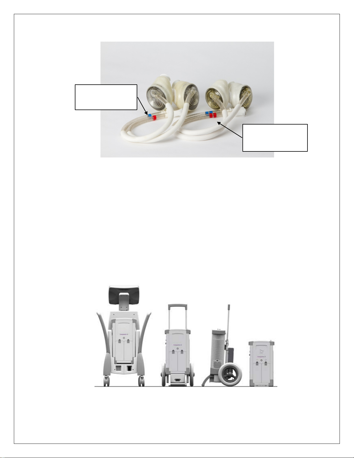
Figure 7-1 – External Air Connection ........................................................................31
Figure 8-1 – Menu Selection in Ambulatory Mode....................................................35
Figure 8-2 – O.R. Mode Entry Screen ........................................................................36
Figure 8-3 – Language Selection Screen ..................................................................37
Figure 8-4 – System Check Menu Screen .................................................................38
Figure 8-5 – Set Date/Time .........................................................................................40
Figure 8-6 – New Patient Setup Screen.....................................................................41
Figure 8-7 – Patient File Copy Screen.......................................................................43
Figure 8-8 – Parameter Adjustment Window ............................................................44
Figure 8-9 – Adjustment of Parameters in O.R. Mode..............................................46
Figure 8-10 – Main O.R. Screen Showing Single Pulse Mode Button.....................47
Figure 8-11 – Flip Screen Menu .................................................................................48
Figure 8-12 – Zoomed View of Pressure Waveform Showing Full Eject Flag........49
Figure 8-13 – Screen Showing Full Fill on the Left and Right Ventricle for a 70cc
TAH-t ............................................................................................................................51
Figure 8-14 – Partial Fill Flow Waveform...................................................................52
Figure 8-15 – Reset Average Hourly Cardiac Output...............................................53
Figure 8-16 – Ambulatory Mode.................................................................................54
Figure 9-1 – I.C.U. Mode Screen – Locked................................................................57
Figure 9-2 – I.C.U. Mode Screen – Unlocked.............................................................58
Figure 9-3 – I.C.U. Mode Parameter Adjustment ......................................................58
Figure 10-1 – Ambulatory Mode.................................................................................61
Figure 10-2 – Ambulatory Mode Maximize Display ..................................................62
Figure 10-3 – Patient File Copy Screen.....................................................................64
Figure 10-4 – Set Date/Time .......................................................................................64