ThermoTek evolution 2 User manual

Vascular Therapy System
(Compressible Limb Sleeve Device)
Customer Service
Sales: 972-874-4949
Web: www.thermotekusa.com
1200 Lakeside Parkway, #200
Flower Mound, TX 75028
0V12X1009M01-D01 Rev D 06/17/21
Manufactured For:
USER MANUALUSER MANUAL

QUICK START
DETAILED INSTRUCTIONS
1
Right
Left
H
O
L
D
F
O
R
3
S
E
C
O
N
D
S
3
Right Leg Pictured
CALF CUFF APPLICATION
Wrap the cuff around the calf, placing the area adjacent to the printing toward
the back of your calf. Secure the hook material to the wrap to hold it in place.
Make sure the wrap is snug, but not too tight.
CORRECT WRAP
PLACEMENT
When both wraps are secured on
your legs, they should look like the
picture above.
TURNING ON THE DEVICE
When the wraps are secured on your
legs press and hold the POWER button
for three seconds until the system
beeps and the light and displays are
illuminated on each unit.
4
PATIENT DEVICE USE
Unit will inflate and deflate to the
specified mode as directed by your
physician. For DVT prophylaxis, be sure
that the unit is in Mode F1 (see user
manual details).
2
POWER OFF: Press and hold the Power Button for three seconds
and it will turn off.
POWER ON: Press and hold the Power Button for three seconds.
The displays will illuminate and the LED will be solid BLUE (the LED will
be solid RED if the battery is low). The unit will display “F1” mode (see
below). After a delay, the wrap will inflate to 55 mmHg pressure and
hold for 10 seconds. The wrap will then deflate for a 50 second “rest”
period and the pressure indicator will step down to 00 (the LED will
blink BLUE).
THERAPY MODES:
The ThermoTek Evolution 2 can operate in 2
Modes, Continuous Inflation (Mode F1) or Step-Up Inflation (Mode F2).
For DVT prophylaxis, ThermoTek recommends that the devices remain
in Mode F1. Press the Power Button to switch between Modes (F1 or F2
will display in the Mode/Counter display). Press the Power Button
again to switch back.
Mode 1: Continuous Inflation: Mode 1: ContinuousSlow Inflation:
Pressure will inflate to 55 mmHg, hold for 10 sec, and deflate for 50 sec.
Mode 2: “Step-Up Inflation”: Pressure will increase at 10 mmHg with
a pause at every increment. Once the unit reaches 55 mmHg, it will deflate
in the same descending increments.
BATTERY INDICATOR
ThermoTek Evolution 2 units include rechargeable batteries that are
charged by connecting the included AC Adapter. Both units can be
charged at the same time. Only charge the batteries with the AC
adapter supplied with the units. The color of the LED indicates state of
Battery Charge. BLUE indicates that the battery is charged (when
device is running and plugged in, LED will be BLUE no matter the state
of charge). RED indicates that the battery charge is LOW and needs to
be charged to avoid therapy interruption. When battery charge is
beginning to get low, the LED may switch between RED and BLUE during
inflation/deflation cycles. When the device is plugged into AC power, the
LED will blink RED until fully charged, where it will be solid BLUE.
TIMER INDICATOR
When the ThermoTek Evolution 2 unit is in use, the indicator on the left
side of the Power Button operates as an hour Counter indicating the
number of hours the device has been used. After the device reaches
“99” hours, the counter will reset to “00”. When ThermoTek Evolution 2
is not in use, the unit saves the previously accumulated working time
(up to 99 hours). When the unit is powered on, the Counter will
continue from the previously saved number.
PRESSURE INDICATOR
When the ThermoTek Evolution 2 unit is in use, the indicator on the right
side of the Power Button operates as a Pressure Indicator. As the unit
inflates the pressure indicator increases. As the unit deflates the pressure
indicator decreases.
INSTRUCTIONS
Charge both devices before first use.
Mode
& Counter
Power Button
Air Pressure
Charging Port LED Indicator
Battery Indicator
Alarm Indicator
The intended use of the EVOLUTION 2 is to aid in the prevention of Deep Vein Thrombosis
(DVT) by helping to stimulate blood flow in the legs. This is accomplished by an electronically
controlled pump delivering a set amount of air to the leg cuffs that, in turn, compress the
calf or calves to aid blood flow out of the lower extremities. The pump will inflate each leg
cuff to a preset pressure of 55mmHg and deflate once the pressure is reached.
CONTENTS:

USER MAINTENANCE
The ThermoTek Evolution 2 contains no serviceable parts.
Contact ThermoTek Customer Service at 877-242-3232.
Inspect the unit and all components for any damage that may have occurred during
shipping or general handling prior to each use (for example, frayed or cut charging cord,
cracked plastic housings, torn cuffs, etc). Refer to image of ThermoTek Evolution 2 for
description of all components.
Do not attempt to connect the wall supply if any damage is noticed.
Avoid subjecting the unit to shocks, such as dropping the pumps.
Do not handle the leg cuffs with any sharp objects. If a bladder is punctured or you notice a
leak, do not attempt to repair the unit or cuffs. Replacement units are available through
customer service. Avoid folding or creasing the bladder during use and transportation of
the unit. Battery is not replaceable; replacement units are available through customer
service. Contact ThermoTek to receive replacements instructions for any damaged items.
STORAGE
Store in a dry location between +10°C (50°F) and +40°C (104°F).
Do not expose to heat exceeding 50°C (122°F) for extended periods of time.
Do not store items in direct sunlight.
DISPOSAL
This unit is an electromechanical device that includes printed circuit boards and
rechargeable batteries. Do not discard in landfill. Consult local county requirements for
proper disposal instructions.
Pump control units contain rechargeable batteries. Do not discard the pump unit in regular
waste. Bring the unit to your local recycle center or contact ThermoTek.
TECHNICAL DATA
Specifications:
Dimensions: 23” x 10.25” x 1.5” (58cm x 26cm x 4cm)
Weight: Approx. 1.43 lb (.65 kg)
Modes of Operation: Mode 1 and Mode 2
Source of Power: DC 5 V or Inner Battery (3.7 volt Li-ion battery)
CAUTION:
Charge batteries using only the power source provided by ThermoTek.
POWER SUPPLY:
Class II, input: 100 - 240 Vac, 50 - 60 Hz, output: 5 V @ 2 Amp)
Use only UL/60601-1 approved power supplies from ThermoTek for use in hospital settings.
Output:
Mode of Operation: Continuous
SYSTEM OPERATING ENVIRONMENT:
Temperature: +10°C (50°F) to +40°C (104°F)
Humidity: 30%-75%. Keep dry.
DEFAULT SETTINGS:
Leg Pressure (not adjustable) 55mmHg Cycle time: 60 Seconds
Mode One: Slow inflation
Mode Two: Step up technology
TOLERANCES:
Pressure 5%.
BATTERY CHARGE:
Takes approximately 3 hours (from depleted state)..
BATTERY RUN TIME:
7 to 9 hours
INTENDED USE
The intended use of the ThermoTek Evolution 2 is to aid in the prevention of Deep Vein
Thrombosis (DVT) by helping to stimulate blood flow in the legs. This is accomplished
by an electronically controlled pump delivering a set amount of air to the leg cuffs
that, in turn, compress the calf or calves to aid blood flow out of the lower extremities.
The pump will inflate each leg cuff to a pre-set pressure of 55mmHg and deflate once
the pressure is reached. The cycles are repeated on each unit until the power is
turned off. Internal rechargeable batteries allow the ThermoTek Evolution 2 to be
completely portable, thus preventing interruptions in treatment.
INDICATIONS FOR USE
The Thermotek Evolution 2, model
0V12X1009M01
, is intended to be an easy to
use portable system, prescribed by a physician, for use in the home or clinical
setting to help prevent the onset of DVT in patients by stimulating blood flow in
the extremities (simulating muscle contractions). This device can be used to:
Aid in the prevention of DVT;
Enhance blood circulation;
Diminish post-operative pain and swelling;
Reduce wound healing time;
Aid in the treatment and healing of: stasis dermatitis, venous stasis ulcers,
arterial and diabetic leg ulcers, chronic venous insufficiency and reduction of
edema in the lower limbs.
The unit can also be used as an aid in the prophylaxis for DVT by persons expecting
to be stationary for long periods of time.
CONTRAINDICATIONS
The ThermoTek Evolution 2 must NOT be used when the following conditions are
present:
Persons with suspected, active or untreated: deep vein thrombosis, ischemic
vascular disease, severe arteriosclerosis, pulmonary edema, severe congestive heart
failure, thrombophlebitis or an active infection;
On a leg where cuffs would interfere with the following conditions: vein ligation,
gangrene, dermatitis, open wounds, a recent skin graft, massive edema or extreme
deformity of the leg; on patients with neuropathy; on extremities that are
insensitive to pain; where increased venous or lymphatic return is undesirable.
WARNINGS AND
PRECAUTIONS
WARNINGS
Contact ThermoTek™Customer Service at 877-242-3232 for any questions or to
request a replacement. Do not attempt to repair the device. Do not attempt to
open or remove covers.
CLEANING AND DISINFECTING
NOTE: Inspect the device and follow the cleaning and disinfecting procedures prior to
each use.
WARNING: Device must be turned off and disconnected from the wall outlet prior to
and during cleaning or disinfecting.
WARNING: DO NOT IMMERSE DEVICE IN ANY LIQUID FOR ANY REASON. DO NOT
PLACE DEVICE IN AUTOCLAVE.
Clean the outer surface of the pump unit using a soft cloth, moistened with soapy
water or 70% isopropyl alcohol. Air dry only.
Clean the exterior of the cuffs using a soft cloth, moistened with soapy water or 70%
isopropyl alcohol. Air dry.
Unit must be completely dry prior to use. To ensure that, leave the device in the OFF
position and disconnected from the wall outlet for at least 30 minutes (and as long as
necessary for the unit to dry completely) after cleaning or disinfecting.
radiators to accelerate drying.
USING THE AC ADAPTER /
BATTERY CHARGER
IMPORTANT:
Charge both devices before first use.
WARNING:
Use only the charger provided by ThermoTek™. The use of the wrong charger can cause excessive
heat, damage to the circuit and shorten the life of the battery.
WHEN DEVICE IS OFF:
Plug in the power supply adapter to the wall socket using the plug located at
the bottom end of the device. The RED “Charging” LED indicator (located above the Power Button) on the device will
illuminate or flash, depending of the state of the charge. When the battery is charging, the LED indicator will be RED.
Once the battery if fully charged, the LED indicator will be solid BLUE.
WHEN DEVICE IS ON:
The AC adapter can be connected while the device is in use. Whenever the device
is ON and the charger is connected and plugged in to the wall socket, the LED indicator on the device will show BLUE.
ALARMS
E1
-
E1 displayed in the Mode/Counter display can indicate that the Battery charge is LOW or that there is an air LEAK.
Battery Low: Power down device and power back on. If LED is RED, this indicates that the battery power is
low. Plug in to charge unit. If this alarm continues to present after charging, call ThermoTek Customer
Service at 877-242-3232.
Low Pressure or Air Leak: Power down device and power back on. If LED is BLUE, this indicates that there is a leak
or issue attaining pressure. Remove wrap and reapply, being sure that the wrap is secure but not tight around calf
and restart device. If this alarm continues to present after reapplication, call ThermoTek Customer Service at
877-242-3232. DO NOT ATTEMPT TO REPAIR THE DEVICE.
E2
-
E2 displayed in the Mode/Counter display indicates that the Battery charge is CRITICALLY LOW.
Connect to wall power to continue use.
Alarm Reset:
System must be power cycled to reset alarms.
WARNING: This device is not protected against water. Equipment is not
suitable for use in the presence of flammable anesthetic mixture with
air, oxygen, or nitrous oxide. The rechargeable batteries supplied in this
unit are not field replaceable. If you have any issues please contact
877-242-3232.for a replacement unit.
The use of accessories, power supplies and cables other than
those specified, with the exception of components sold by the
manufacturer of the ThermoTek Evolution 2 as replacement parts,
may result in increased emissions or decreased immunity of the
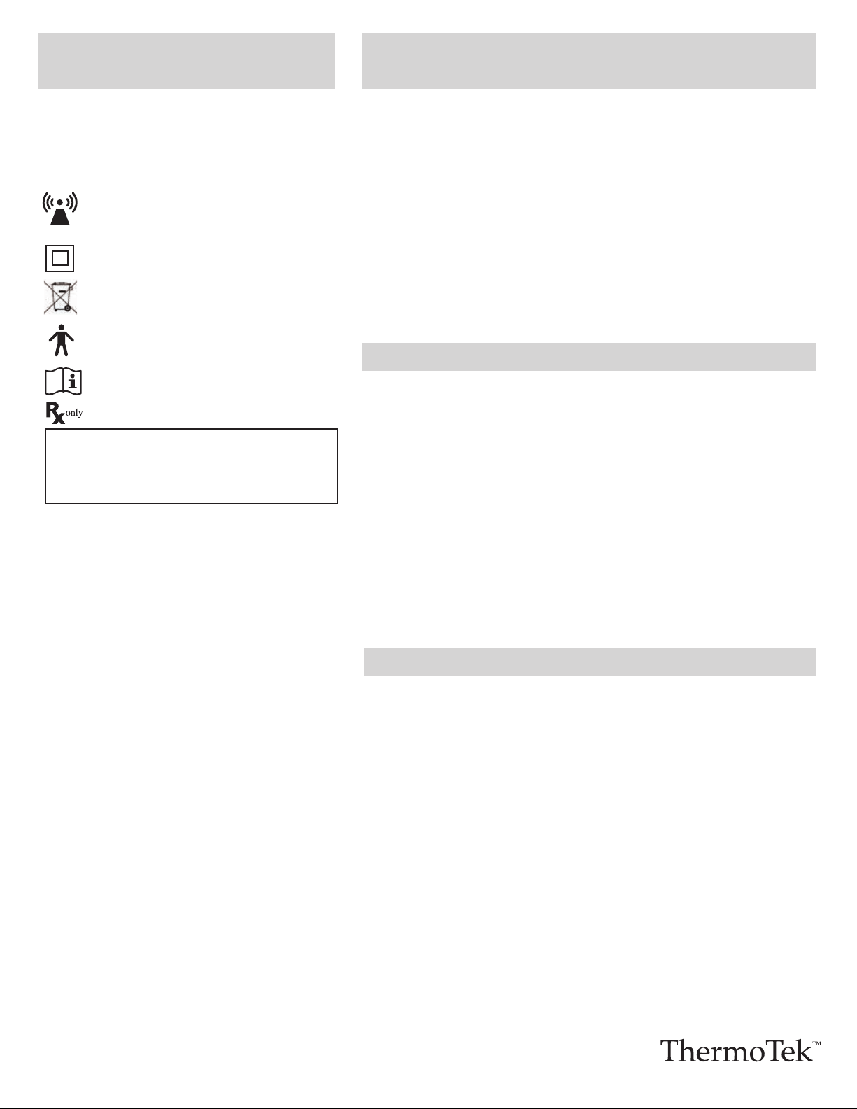
ThermoTek Evolution 2.
Designates Class II medical electrical equipment.
This unit is an electromechanical device that includes printed
circuit boards and rechargeable batteries. Do not discard in landfill.
Consult local county requirements for proper disposal instructions.
This symbol designates the degree of protection against electrical
shock from the wrap as being a type B applied part.
Consult instructions for use.
CAUTION: Federal Law restricts this device to sale by or on the
order of a physician.
Do not remove the pump unit from the cuff. Do not attempt to modify or change
the device. NEVER attempt any service while the device is in use. Do not attempt
to connect the wall supply if any damage is noticed. Avoid subjecting the unit to
physical abuse, such as dropping the pumps. Do not handle the leg cuffs with any
sharp objects. If a bladder is punctured or you notice a leak, do not attempt to
repair the unit or cuffs. Replacement units are available through customer
service. Avoid folding or creasing the bladder during use and transportation of the
unit. Rechargeable Battery is not replaceable; replacement units are available
through customer service. Contact ThermoTek to receive replacements
instructions for any damaged items.
ThermoTek Evolution 2 is a Medical Electrical Device. The following are precautions
specific
to Medical Electronic Devices:
instructions refer to “Cleaning and Disinfecting” section.
air or with oxygen or nitrous oxide.
room temperature.
affectedbyMedical Electrical Devices.
CAUTIONS
This device is to be sold by or on the order of the physician.
Operation of the device can be done by the patient.
The ThermoTek Evolution 2 cuffs are designed for single patient use. The device
must be
ONLY used for its intended use by the patient prescribed. The device
must not be transferred to another patient.
Stop using device if swelling, skin irritation or any other unpleasant or painful
sensation occurs and consult a Physician.
Loosen cuffs immediately if pulsation or throbbing occurs as the cuffs may be
wrapped too tightly.
Patients with diabetes or vascular disease require frequent skin assessment.
Consult a Physician.
Patients who use warming devices in combination with cuffs require frequent
assessment as skin irritation may occur. Consult a Physician.
Patients positioned in the supine lithotomy position (with or without cuffs) for
an extended period of time require special attention to avoid extremity
compartment syndrome. Consult a Physician.
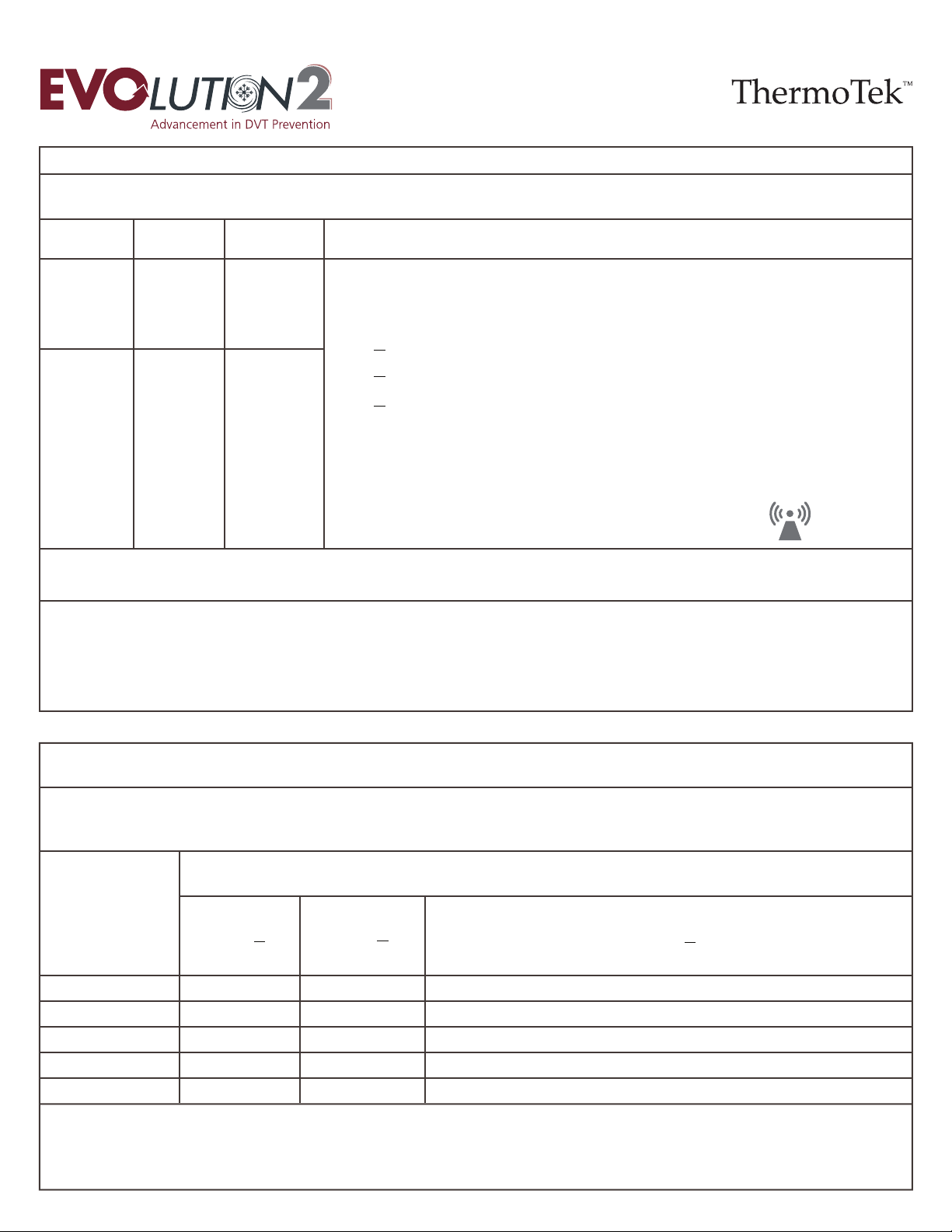
ELECTROMAGNETIC COMPATIBILITY (EMC)
TABLES - RF EMISSIONS CLASS B
GUIDANCE AND MANUFACTURER’S DECLARATION - ELECTROMAGNETIC IMMUNITY
RECOMMENDED SEPARATION DISTANCE BETWEEN PORTABLE AND MOBILE RF COMMUNICATIONS EQUIPMENT AND THE ThermoTek Evolution 2
The ThermoTek Evolution 2 is intended for use in the electromagnetic environment specified below.
The customer or the user of the ThermoTek Evolution 2 should assure that it is used in such an environment.
Conducted RF
IEC61000-4-6
Portable and mobile RF communications equipment should be used no closer to any part of the ThermoTek Evolution 2,
including cables, than the recommended separation distance calculated from the equation applicable to the frequency
of the transmitter.
Recommended separation distance
150 KHz to 80 MHz
80 MHz to 800 MHz
800 MHz to 2.5 GHz
Radiated RF
IEC61000-4-3
NOTE 1: At 80 MHz and 800 MHz, the higher frequency range applies.
NOTE 2: These guidelines may not apply in all situations. Electromagnetic propagation is affected by absorption and reflection from structures, objects and people.
The ThermoTek Evolution 2 is intended for use in an electromagnetic environment in which radiated RF disturbances are controlled. The customer or the user of the
ThermoTek Evolution 2 can help prevent electromagnetic interference by maintaining a minimum distance between portable and mobile RF communications equipment (transmitters)
and the ThermoTek Evolution 2 as recommended below, according to the maximum output power of the communications equipment.
Separation distance according to frequency of transmitter
m
Rated maximum output
power of transmitter
W
0.01
0.1
1
10
100
0.12
0.38
1.2
3.8
12
0.12
0.38
1.2
3.8
12
0.23
0.73
2.3
7.3
23
150 KHz to 80 MHz 80 MHz to 800 MHz 800 MHz to 2.5 GHz
a
Field strengths from fixed transmitters, such as base stations for radio (cellular/cordless) telephones and land mobile radios, amateur radio, AM and FM radio broadcast and
TV broadcast cannot be predicted theoretically with accuracy. To assess the electromagnetic environment due to the fixed RF transmitters, an electromagnetic site survey should be
considered. If the measured field strength in the location in which the ThermoTek Evolution 2 is used exceeds the applicable RF compliance level above, the ThermoTek Evolution 2
should be observed to verify normal operation. If abnormal performance is observed, additional measures may be necessary, such as reorienting or relocating the ThermoTek Evolution 2.
b
Over the frequency range 150 kHz to 80 MHz, field strengths should be less than [V1] V/m.
NOTE 1: At 80 MHz and 800 MHz, the separation distance for the higher frequency range applies.
NOTE 2: These guidelines may not apply in all situations. Electromagnetic propagation is affected by absorption and reflection from structures, objects and people.
For transmitters rated at a maximum output power not listed above, the recommended separation distance in meters (m) can be estimated using the equation applicable to
the frequency of the transmitter, where P is the maximum output power rating of the transmitter in watts (W) according to the transmitter manufacturer.
where P is the maximum output power rating of the transmitter in watts (W) according to the transmitter
manufacturer and d is the recommended separation distance in meters (m).
Field strengths from fixed RF transmitters, as determined by an electromagnetic site survey
a
, should be less than
the compliance level in each frequency range
b
.
Interference may occur in the vicinity of equipment marked with the following symbol:
3 V/m
80 MHz to 2.5
GHz
10 V/m
3Vrms
150 kHz to 80
MHz
3Vrms
Immunity
Test
IEC 60601
Test Level
Compliance
Level
Electromagnetic Environment Guidance
d = 1.2 √P
d = .35 √P
d = .70 √P
d = 1.2 √Pd = .35 √Pd = .70 √P

GUIDANCE AND MANUFACTURER’S DECLARATION - ELECTROMAGNETIC EMISSIONS
The ThermoTek Evolution 2 is intended for use in the electromagnetic environment specified below.
The customer or the user of the ThermoTek Evolution 2 should assure that it is used in such an environment.
RF Emissions CISPR11
Harmonic Emissions IEC
61000-3-2
Voltage Fluctuations IEC
61000-3-3
RF Emissions CISPR11
Class B
Class A
Complies
Group 1
The ThermoTek Evolution 2 is suitable for use in all establishments, including domestic establishments and those directly
connected to the public low-voltage power supply network that supplies buildings used for domestic purposes.
The ThermoTek Evolution 2 uses RF energy only for its internal function. Therefore, its RF emissions are very low and are not
likely to cause any interference in nearby electronic equipment.
Emissions Tests Compliance Electromagnetic Environment Guidance
GUIDANCE AND MANUFACTURER’S DECLARATION - ELECTROMAGNETIC IMMUNITY
The ThermoTek Evolution 2 is intended for use in the electromagnetic environment specified below.
The customer or the user of the ThermoTek Evolution 2 should assure that it is used in such an environment.
Electrostatic
Discharge (ESD)
IEC 61000-4-2
Electrical Fast
Transient/Burst
IEC61000-4-4
Surge
IEC61000-4-5
±1kV differential
mode
±2kV common mode
±1kV differential
mode
±2kV common mode
Mains power quality should be that of a typical commercial or hospital environment.
Mains power quality should be that of a typical commercial or hospital environment. If the user of the
ThermoTek Evolution 2 requires continued operation during power mains interruptions, it is recommended
that the ThermoTek Evolution 2 be powered from an uninterrupted power supply or a battery.
Voltage
dips, short
interruptions
and voltage
variations on
power supply
input lines
IEC61000-4-11
Power Frequency
(50/60Hz)
Magnetic Fields
IEC61000-4-8
30 A/m at
50 or 60 Hz
30 A/m at
50 or 60 Hz
Power frequency magnetic fields should be at levels characteristic of a typical location in a typical
commercial or hospital environment.
<5%U
T
(>95% dip in U
T
)
for 0.5 cycle
40%U
T
(60% dip in U
T
)
for 5 cycles
70%U
T
(30% dip in U
T
)
for 25 cycles
<5%U
T
(>95% dip in U
T
)
for 5 seconds
NOTE: U
T
is the a.c mains voltage prior to application of the test level.
<5%U
T
(>95% dip in U
T
)
for 0.5 cycle
40%U
T
(60% dip in U
T
)
for 5 cycles
70%U
T
(30% dip in U
T
)
for 25 cycles
<5%U
T
(>95% dip in U
T
)
for 5 seconds
±2kV for power
supply lines
±1kV for input/
output lines
±2kV for power
supply lines
±1kV for input/
output lines
Mains power quality should be that of a typical commercial or hospital environment.
Floors should be wood, concrete or ceramic tile. If floors are covered with synthetic material,
the relative humidity should be at least 30%.
±8kV contact
±15kV air
±8kV contact
±15kV air
Immunity
Test
IEC 60601 Test
Level
Compliance
Level Electromagnetic Environment Guidance
ELECTROMAGNETIC COMPATIBILITY (EMC)
TABLES - RF EMISSIONS CLASS B
Table of contents
Other ThermoTek Medical Equipment manuals


