Penn Photoreactor m2 User manual

User Manual
Rev C
Penn Photon Devices, LLC
1055 Mensch Dam Road
Pennsburg, PA 18073, USA
Tel: (011) 267-923-8798

2
Table of Contents
1Introduction......................................................................................................................................... 3
2Safety................................................................................................................................................... 3
2.1 Explanation of labels .................................................................................................................... 4
3System Overview ................................................................................................................................. 5
4Setup.................................................................................................................................................... 6
4.1 System Components .................................................................................................................... 6
4.2 Choosing a Location ..................................................................................................................... 6
4.3 Connecting the Power Cord ......................................................................................................... 6
5Operation............................................................................................................................................. 7
5.1 Setup ............................................................................................................................................ 7
5.2 Performing a Photoredox Cycle ................................................................................................... 9
5.3 Termination, Turning the Unit “Off”.......................................................................................... 11
6System Information ........................................................................................................................... 12
7Proper Care and Handling ................................................................................................................. 12
7.1 Cleaning, Disinfection, and Disposal .......................................................................................... 12
8Maintenance...................................................................................................................................... 12
9Technical Data................................................................................................................................ 13
10 Product Ratings.............................................................................................................................. 14

3
1Introduction
The Photoreactor m2 is a benchtop instrument designed for chemists and researchers to accelerate
chemical reactions using photoredox catalysis. The Photoreactor m2 combines LED illumination,
mechanical stirring and cooling in one device. The user defined parameters of temperature, intensity,
stir rate and time, creates a valuable tool for repeatability, traceability, efficiency and consistency of
results. The Photoreactor m2 addresses the potential to streamline synthetic sequences, and create
valuable strategies for addressing some of the challenges of molecule construction in drug discovery.
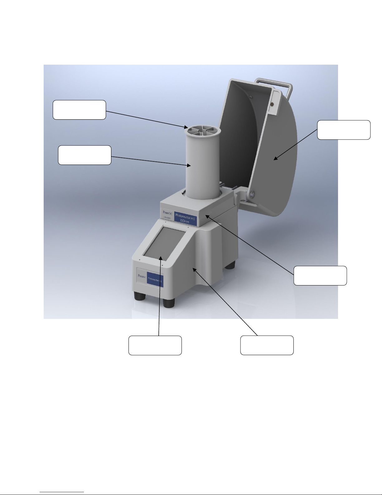
Key Features:
•Photoreactor m2 is a complete benchtop instrument to accelerate photoredox catalysis
•Modular design allows for use with a variety of wavelengths from 365nm to 450nm
•360 degree reflective environment maximizes surface area photon capture
•Light shield interlock prevents user exposure to harmful light rays
•Interactive touch screen controls reaction parameters
•Intertek ETL, CE, and CB approved
•User defined parameters including temperature, light intensity, fan speed and stirring
•Auto stop, pause and reset options
•Supports vial sizes gc, 4, 8, 20, 40 ml
•Temp feedback using a k-type thermocouple
2Safety
Prior to use, the operator should thoroughly read the instructions for use. Using this device without
reading and understanding the instructions for use may result in operator injury or damage to the
equipment.
The device contains a powerful LED that produces extremely bright light. Do not look into the back end
of the device when the LED is activated as this may result in eye damage.
Only use the device with approved accessories. Proper care must be taken during setup and operation
to prevent injury to operators and other personnel or damage to the unit.
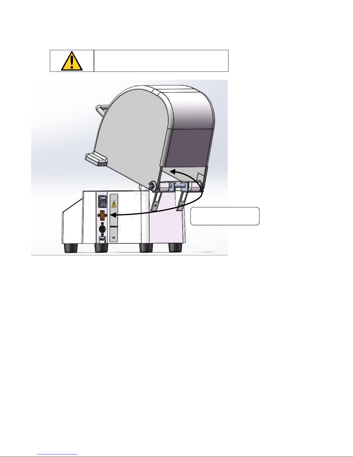
The unit is equipped with multiple safety features including an interlock device that will not permit LED
emission when the light shield is not in place. Keep magnets away from the device to prevent
accidental interlock activation.
No modification of this equipment is allowed.
Never open or remove the bottom cover. Qualified
personnel must perform all maintenance.

4
The Illuminator unit requires adequate airflow to
maintain proper cooling. Ensure the ventilation holes
and bottom of the unit are unobstructed and a
minimum of 4” clearance is provided in rear of unit.
If the Illuminator is used in a manner not specified
within this manual, the protection provided by the
equipment might be impaired. It is the
responsibility of the user to follow all applicable
safety guidelines in prevention of injury or damage
to the unit.
Use of the equipment with an unapproved power
supply may cause damage to the device and/or power
supply and may result in injury.
It is the responsibility of the user to assess and mitigate
any hazards that may result from a mixing
interruption.
It is the responsibility of the user to assess and mitigate
any hazards that may result from mixing volatile or
flammable materials. Users shall comply with all
applicable safety and accident-prevention procedures
for laboratory work.
Device intended for a variety of chemical reactions;
Device to be used by trained operator in a laboratory
setting.
Operation of multiple devices simultaneously in a
single enclosed area may require ear protection
Explanation of labels
Manufacturer.
Caution –Read User Manual.

5
3System Overview
Light Shield
LED Module
Touchscreen
Base Unit
Reflector
Vial Holder

6
4Setup
System Components
The Photoreactor m2 is comprised of the following components:
▪Base Unit
▪450nm LED Module*
▪8ml Reflector
▪40ml Reflector
▪gc Vial Holder
▪4ml Vial Holder
▪8ml Vial Holder
▪20ml/40ml Vial Holder
▪Power Supply
▪Power Cable
*420nm and 365nm wavelength LED modules are separately available
Choosing a Location
Set the Photoreactor m2 horizontally on its four neoprene feet on a flat surface in a place that allows for
adequate air ventilation on the back and bottom. Do not place the Photoreactor m2 on top of paper or
loose material that may be drawn into any ventilation port. Do not position the unit so that the back of
the unit is obstructed. The Photoreactor m2 should only be transported in the horizontal position.
NOTE:
For adequate ventilation, maintain at least 4” of
clearance around all sides of the unit in an unenclosed
space.
Connecting the Power Cord
Insert the power supply receptacle-end into the receptacle on the side of the unit. Insert the power cord
plug into a standard AC outlet.
Warning: To avoid risk of electric shock, this
equipment must only be connected to a supply mains
with a protective earth.

7
The unit must be powered with the supplied power supply (85-264V, 50/60 Hz, Full Range).
5Operation
Setup
Once the power cord is connected set the ON/OFF (I/O) switch to the ON (I) position.
Add the contents to vial with appropriately sized stir bar (if required) and insert into the vial
holder. (Note: select the vial holder that corresponds to the correct vial size and ensure that it
is fully seated).
Insert the vial holder into the corresponding reflector and ensure that the vial is still fully seated
and is roughly concentric to the reflector.
With the light shield in the open position, select the desired LED module and insert it into the
base unit, being careful to properly align the connector pins.
Insert the reflector into the LED module by aligning the tabs with the slots and turning the
reflector until it stops.
If temperature monitoring or control is desired, connect a K-type thermocouple to the K-type
connector. Pass the thermocouple through the opening at the rear of the light shield (see
below) and place the distal end within the vial or at the desired location.
Lower the light shield and verify that the interlock is engaged by ensuring that the “Interlock”
indicator is green on the touch screen.
NOTE:
Please note that the viscosity of the stirred material will affect the
ability of the stir bar to remain coupled to the rotating magnet.
Materials of high viscosity must be stirred at slower speed settings.
Warning: Magnetic stirring cannot be achieved with all combinations of stir bars, reflectors, vial
holders, and vials. It is recommended that the user select the reflector (8ml or 40ml), which
minimizes the distance from the bottom of the vial to the LED module. The user must determine
the appropriate combination of stir bar, reflector, vial holder and vial to optimize magnetic stirring.
Power Supply
Receptacle
Power Switch
K-type connector
USB Receptacle

8
Warning: To avoid damage to the device, ensure the
thermocouple does not come into contact with any
moving parts, i.e. stir magnet, motor or fan
Thermocouple path

9
Performing a Photoredox Cycle
The user interface (GUI) initiates on the main display (shown
left). The device is configured with the following default
settings.
•Duration (HH:MM:SS) is 01:00:00
•Post-cool duration (MM:SS) is 00:30
•LED intensity (%) is 50
•Fan Control is set to Manual
•Fan (rpm) is set to 6800 (Max)
•Stir(rpm) is 100 (Min)
To operate the device with the default settings, simply press
“Start”.
To customize set points press “Change Settings” on the main display.
The user interface opens the settings screen (shown left)
The following set points can be customized.
•Duration (HH:MM:SS) up to 99:99:99
•LED intensity (%) –1% to 100%
•Post-cool duration (MM:SS) - 00:00 to 59:59
•Stir(rpm) –100 to 2000
•Fan Control –Manual / Auto
•Manual Fan (rpm) –2800 to 6800*
•Auto Fan/Temperature Control (Temp (C) –0 to 50
When the Fan Control is set to Auto, the Fan (rpm) will
dynamically change to maintain the target temperature set
point.
Ensure Thermocouple is in vial while operating in
auto fan mode

10
To change the set point of a
given parameter select it on the
touch screen. This will provide a
display corresponding to the
parameter you have chosen as
shown on the right. The dial
may be rotated to select the
desired setting. Alternatively,
pressing the “KEY” button will
allow the user to enter an exact
value. Pressing the “DONE”
button will accept the value.
Once the parameters have been set, press “Done” on the Change Settings screen to return to
the main display.
Press “Start” to begin.
All values may be edited at any time during operation.
The unit will begin a 10 second precooling cycle as indicated by the Status field. The reported
time will show the countdown from 10 seconds. The fan and stir motor will start and the actual
RPMs will be displayed. RPM values are expected to deviate slightly from the set values. At this
point, all values can still be edited by changing the parameters as described above. Changes in
set-points will take effect as soon as the “DONE” button is pressed on the dial or keypad
screens, with the exception of the LED as it will not be emitting at this point.
Once the precooling countdown reaches 0, the LED will activate at the set intensity. The Status
will update to running. The count will start from the duration set value.
Note: If the duration set value is edited during operation to a value less than the elapsed time,
the device will begin a post cooling cycle.
It is recommended to pause operation prior to changing the duration set value.
Once the cycle has completed, the unit will begin post cooling as indicated by the status field.
The LEDs will stop emitting, however the fan and stir bar will continue to rotate until the
countdown has reached 0.
During the operation the cycle can be “Paused”. The LED will stop emitting and the fan and stir
bar will stop rotating. The LED exposure (HH:MM:SS) and Time Remaining (HH:MM:SS) will
pause.

11
The Status field will indicate “Paused” and the Pause button will change to “Resume”. Press
“Resume” to restart the device. The LED exposure and Time Remaining count will continue
from the point in the cycle when it was paused.
Opening the light shield during a cycle will also pause the device.
Upon completion of a cycle, the unit will display status “Complete”. Before initiating another
reaction or changing parameters, the device must be “Reset”. The “reset” button will reset the
device to the parameters set for the last cycle. Parameters may be changed as described
previously and another reaction may be initiated.
During a cycle, the Stop button will immediately halt all operations. Similar to a completed
cycle, the device must be reset from the stopped condition before initiating another reaction or
changing parameters.
Termination, Turning the Unit “Off”
Unplugging the unit or switching off the unit while it is running will cause no harm to the system,
nor will it cause an unsafe condition.
All of the following methods can be used to turn off the unit, safely:
•Side Panel Power Switch.
•Disconnecting Mains Power.

12
6System Information
To display the system information press the “System Info” button on the main display.
The user interface opens the system information screen.
The GUI FW and Control FW version display the latest FW version on the device.
The S/N is set by manufacturer during assembly and matches the control label S/N on the base of the
device.
7Proper Care and Handling
Remove Photoreactor m2 and accessories from packaging and observe all labeling. Immediately
notify the manufacturer of any defects.
Cleaning, Disinfection, and Disposal
•Clean and disinfect the external housing of the Photoreactor m2 with a mild detergent.
•Wipe with mild detergent, do not spray.
•Never clean any internal electronics with liquid cleaners. If necessary, remove all dust from
external surfaces with dry compressed air.
•Photoreactor m2 units shall be disposed of via local and applicable regulations based on the
intended use.
8Maintenance
The Photoreactor m2 is designed to operate for many years without any maintenance required.
No user-changeable fuses are included. Consult manufacturer.

13
All maintenance is to be performed by qualified
personnel only. Do not attempt internal
maintenance or repair. Consult the manufacturer
for further instructions.
Contact Information:
Penn Photon Devices, LLC
1055 Mensch Dam Road
Pennsburg, PA 18073, USA
Tel: (011) 267-923-8798
9Technical Data
Cover closed
•Width: 12.2 cm (4.8 inches)
•Height: 27.2 cm (10.7 inches)
•Depth: 28.2 cm (11.1 inches)
Cover open
•Width: 12.2 cm (4.8 inches)
•Height: 33.8 cm (13.3 inches)
•Depth: 42.67 cm (16.8 inches)
•Weight: Approximately 2 kg (4.4 lbs.)
•Operating mode: Continuous
•Main cable: 10 A/250 V
•Power supply: 85-264V, 50/60 Hz, 120VA
•Expected Service Life: 5 years
•Cleaning: Surface cleaning with mild detergent
Ambient conditions for operation
•Temperature: 5° to 40°C (41° to 104°F)
•Rel. humidity: 0% to 80% non-condensing for temperatures up to 31°C (88°F) decreasing
linearly to 50% at 40°C (104°F)
•Air pressure: 700 hPa to 1060 hPa
Ambient conditions for storage (in shipping packaging)
•Temperature: -20° to +50°C (-4° to 122°F)
•Rel. humidity: 0% to 100%, non-condensing

14
10 Product Ratings
For all CE compliance questions, EU customers may contact;
Necsel IP, Inc., an Ushio Group company
101 Panton Road,
Vergennes, VT 05491, USA
Tel: (011) 802 877 2182
Table of contents
Popular Laboratory Equipment manuals by other brands

Terumo
Terumo CAPIOX NX19 Instructions for use

Phcbi
Phcbi MIR-554 Series operating instructions

Lonza
Lonza PAGEr Minigel Chamber instruction manual

DrBrowns
DrBrowns AC178-INTL Instructions for use

Agilent Technologies
Agilent Technologies 1220 Infinity II LC Installation note

Miele
Miele IR 6002 operating instructions

Thermo Scientific
Thermo Scientific NanoDrop One user guide

Ideal Vacuum
Ideal Vacuum ExploraVac Series installation guide

Lahoux Optics
Lahoux Optics Spotter Pro V user manual

Sarstedt
Sarstedt SMC 6 instruction manual

Bürkle
Bürkle 5314-2000 Directions for use

Fritsch
Fritsch LABORETTE 27 operating instructions