1401 North Plano Road, Richardson, Texas 75081
Phone: 972-234-3202 | Fax: 972-497-0441 PENNBARRY 2
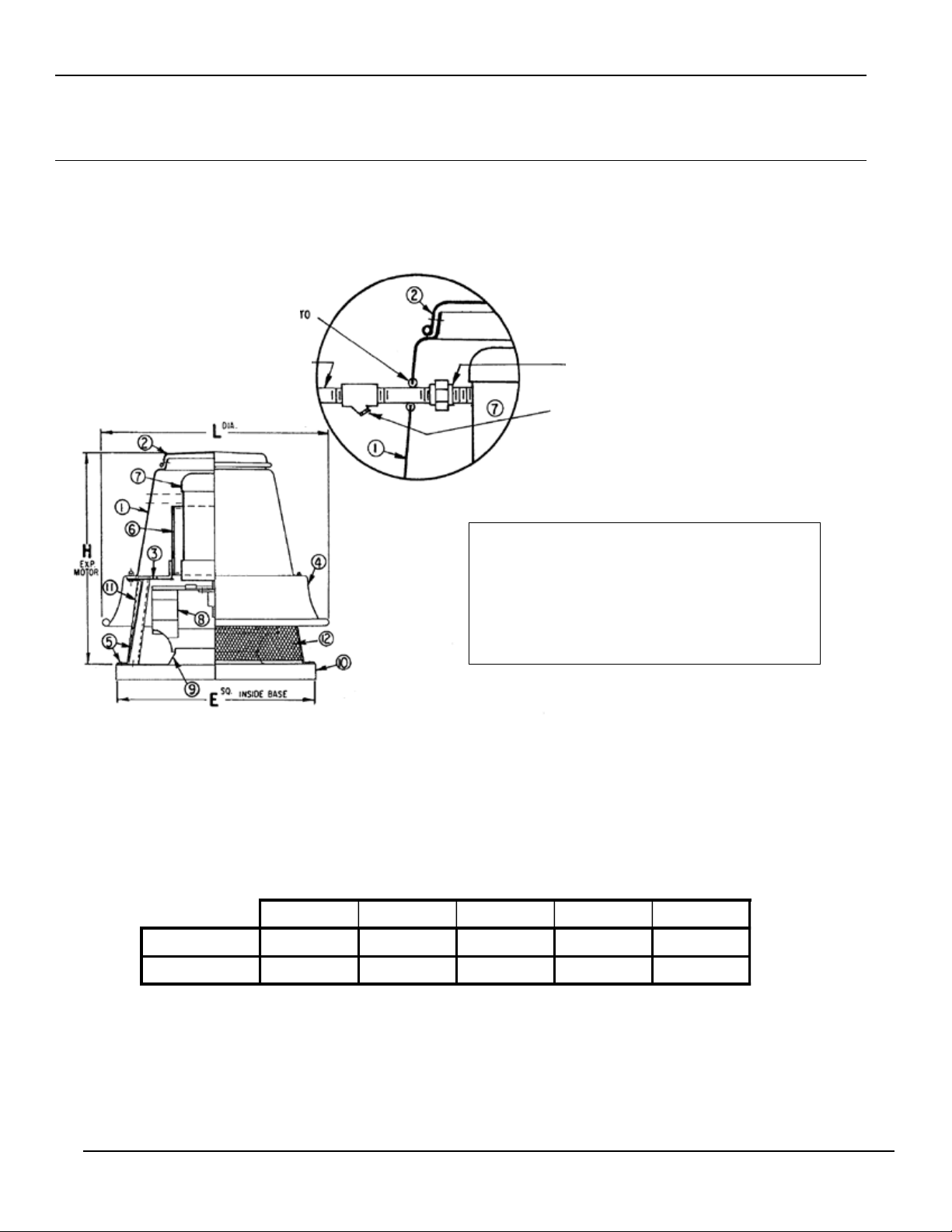
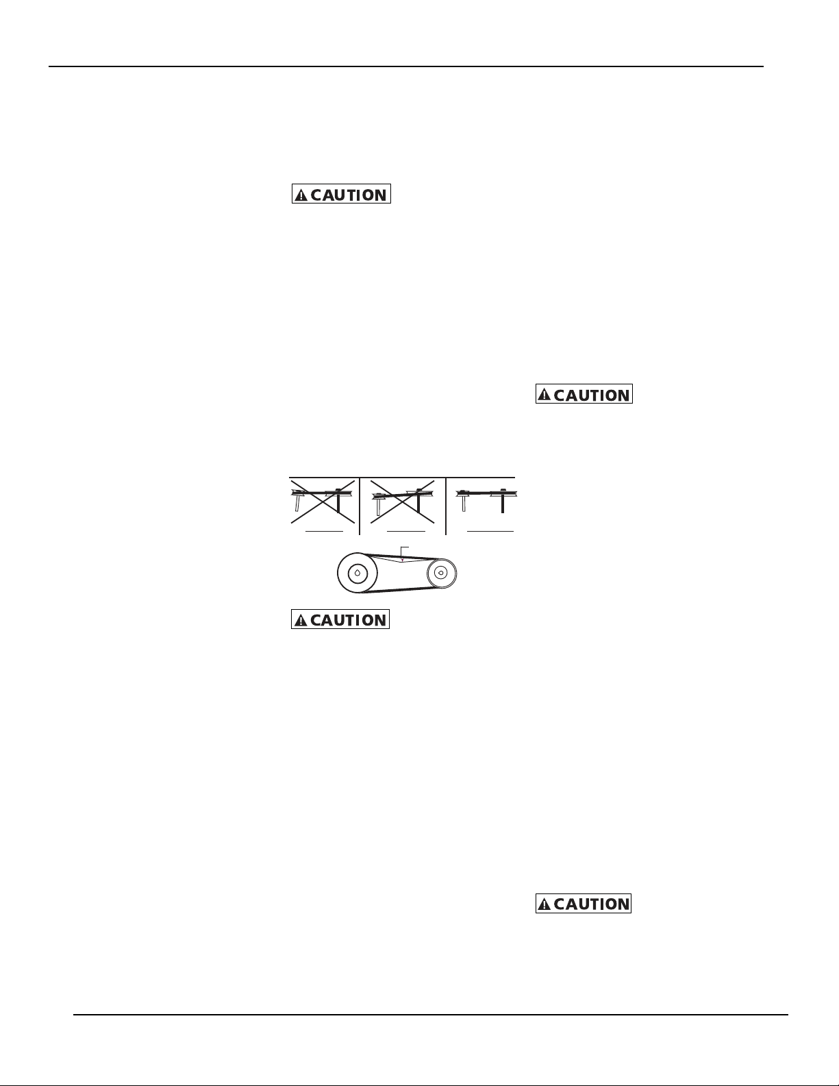
Not to exceed 1/64” per inch of span
WRONG WRONG CORRECT
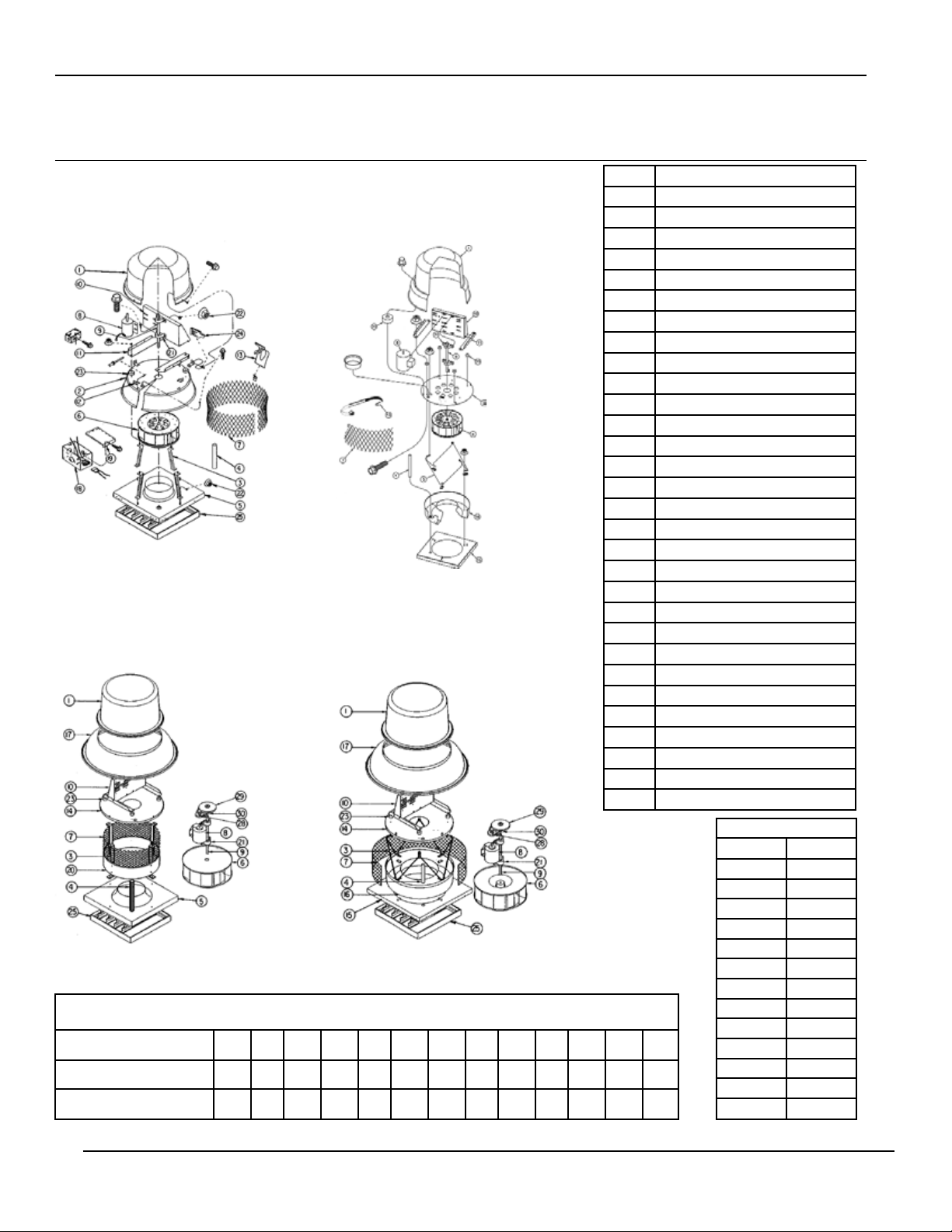
Operation & Maintenance Manual Domex, Centrifugal Roof, Direct & Belt Drive Exhausters
When power lines are brought up to the
unit, provide a generous amount of slack
to allow for motor adjustments and to per-
mit movement of motor for belt tension ad-
justments. Ground motor adequately and
securely. Protect power lines from sharp
objects. Do not kink power line or permit it
to contact hot surfaces, chemi-cals, grease
or oil. Use only UL recog-nized electrical
parts, rated for proper voltage, load and
environment. Check motor name plate.
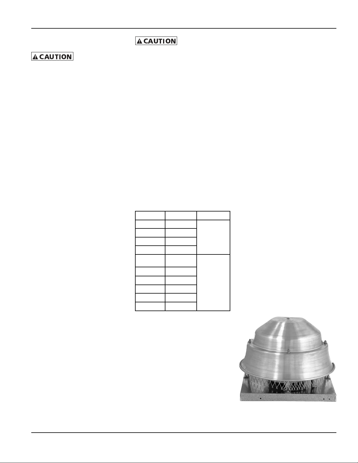
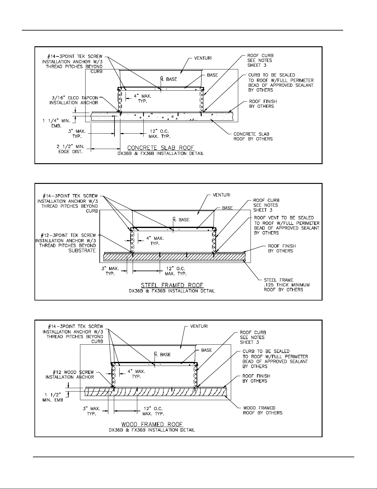
ANCHORING AND SECURING THE
VENTILATOR: ROOF MOUNTING
Whenever possible, anchor the fan by fas-
tening through the vertical portion of the
mounting ange. The type, size and num-
ber of fasteners depends upon the unit size
and curb construction. If code or specica-
tion prescribes fastening through the top
(vertical portion) of the mounting ange,
use neoprene or lead washers under the
head of each fastener.
Guy down large units installed in areas
subject to high winds or unusual eld con-
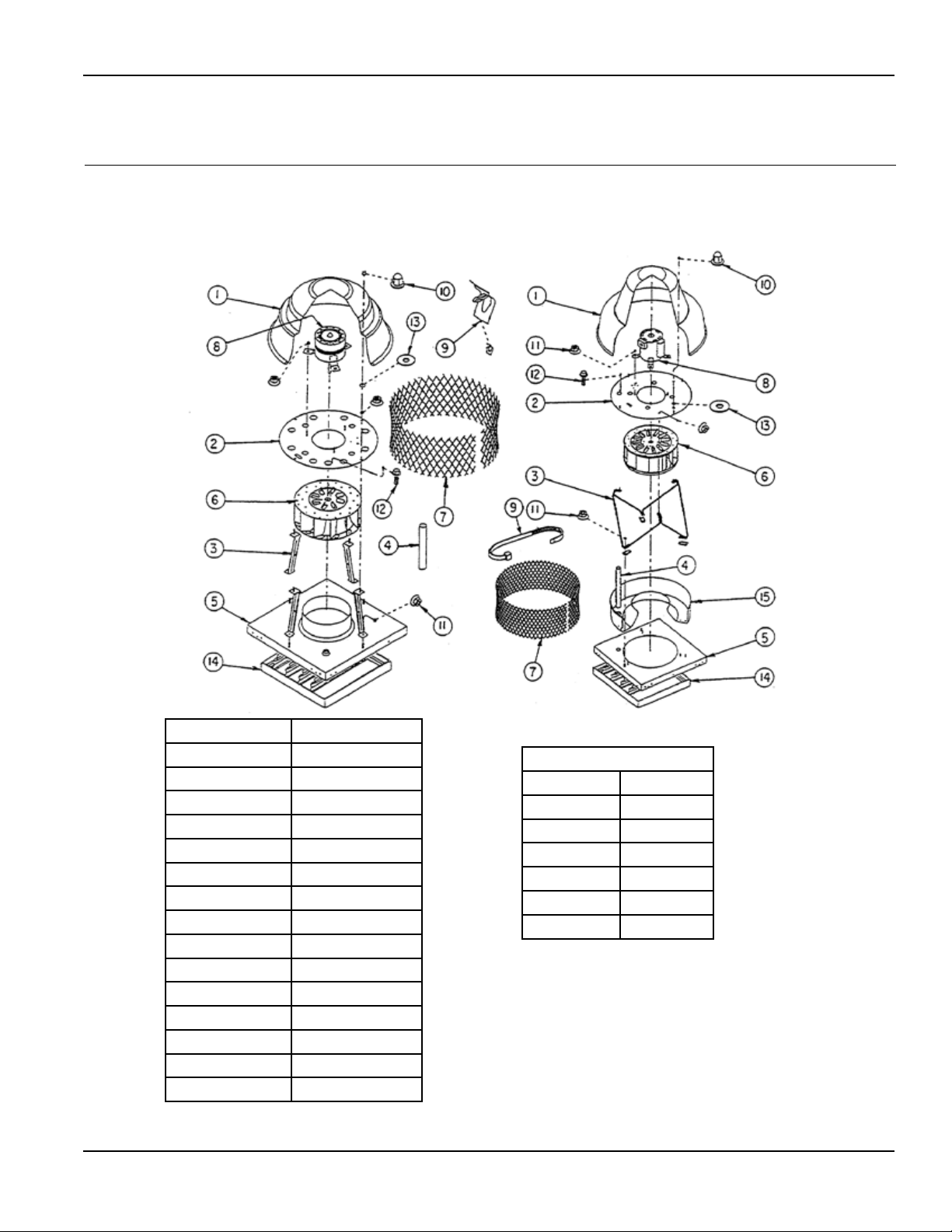
ditions. If the installer removes any venti-
lator parts to facilitate installation or elec-
trical connections, reassemble all parts by
replacing all spacers, washers, nuts, bolts,
fasteners and components exactly as they
were found prior to removal. Draw all fas-
teners tight and secure. Fasteners should
be protected against corrosion.
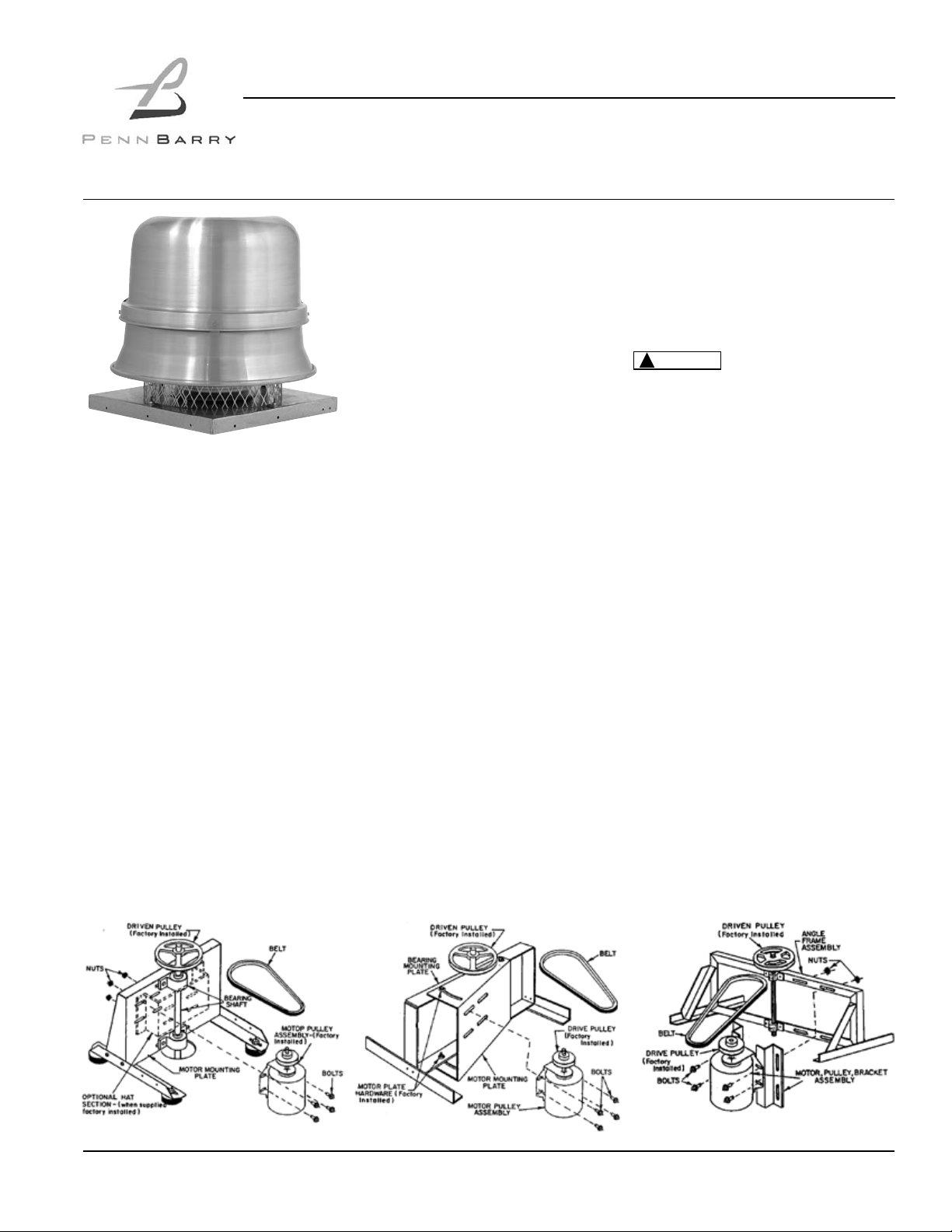
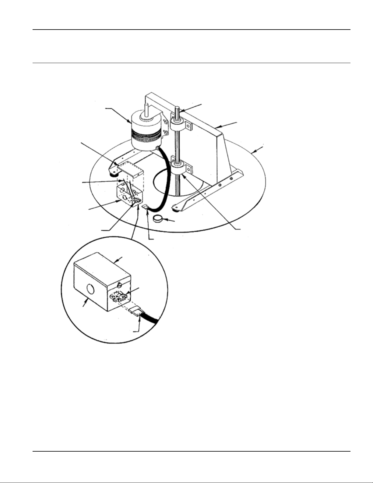
MOTOR INSTALLATION PROCEDURES
1. Install motor pulley assembly (bracket if
provided - type 3) with hardware pro-
vided through holes in motor mount-
ing plate/frame. Keep driven pulley
and drive pulley in line. (Do not tighten
hardware).
2. Install belt over drive and driven pul-
leys, pull up on motor mounting plate/
bracket until belt is tight. Tighten motor
plate hardware.
3. Wire motor or plug harness connec-tor
(from motor if equipped) into terminal
socket at end of junction box. Unit is
now ready to test to check for smooth
operation.
4. See belt adjustment label, and Fig.
4, for more details.
5. Check for proper wheel rotation.
Start-Up and Operation
Carefully inspect the unit before start-up.
All motor bearings should be properly lu-
bricated and all fasteners should be se-
curely tightened. Rotate centrifugal wheel
by hand to insure free movement.
Before placing hand
on centrifugal wheel
or belts, lock out power source.) Check all
set-screws and keys. Tighten when neces-
sary.
Check condition of belts and the amount
of tension prior to start-up. DO NOT over-
tighten, as bearing damage will occur.
Recommended belt tension should per-
mit deection of 1/64” per inch of span.
Exercise extreme care when adjusting
belts as not to misalign the pulleys. Any
misalignment will cause a sharp reduction
in belt life and produce squeaky, annoying
noises. On units equipped with two groove
pulleys, adjust all belts with equal tension.
Belts must be adjusted after approximate-
ly 40 hours of operation.
Figure 4: Pulley Alignment & Tension
Whenever belts
are removed or
installed, never force belts over pulleys
without loosening motor rst to relieve
belt tension.
Make sure inlets and approaches to the
unit are free from obstruction. To assure
maximum air movement, make sure ade-
quate supply air is available to ventilated
space.
Before putting fan into operation, com-
plete the following check list:
a. Turn off and LOCK OUT the power
source.
b. Make sure installation is in
accordance with manufacturer’s in-
structions.
c. Check and tighten all fasteners.
d. Spin centrifugal wheel to see
if rotation is free.
e. Check all set-screws and keys:
tighten if necessary.
f. Torqued set screws have a colored
Torque Seal mark indicating the cor-
rect torque has been applied.
g. Check belt or direct drive coupling
for alignment (use recommended
belt tension gauges).
h. Check belt for proper
sheave selection.
i. Make sure there is no foreign or
loose material in ductwork leading to
and from fan or in the fan itself.
j. Properly secure all safety guards.
k. Secure all access doors to fan
and ductwork.
l. Check line voltage with
motor nameplate.
m. Check wiring.
(On single phase mo-
tors, the terminal
block must be set up in accordance with
the nameplate instructions and/or wiring
diagram. This set up must match the line
voltage. If the motor is multi-speed or
multi-voltage, the winding leads must be
grouped and connected as shown on the
motor wiring diagram. The line voltage
must correspond with proper grouping
of motor leads. The wiring diagram must
be followed explicitly or serious motor or
starter damage will occur.) Don’t operate
at RPM higher than catalog.
The ventilator has been checked at the fac-
tory prior to shipment for mechanical noises.
If mechanical noises should develop:
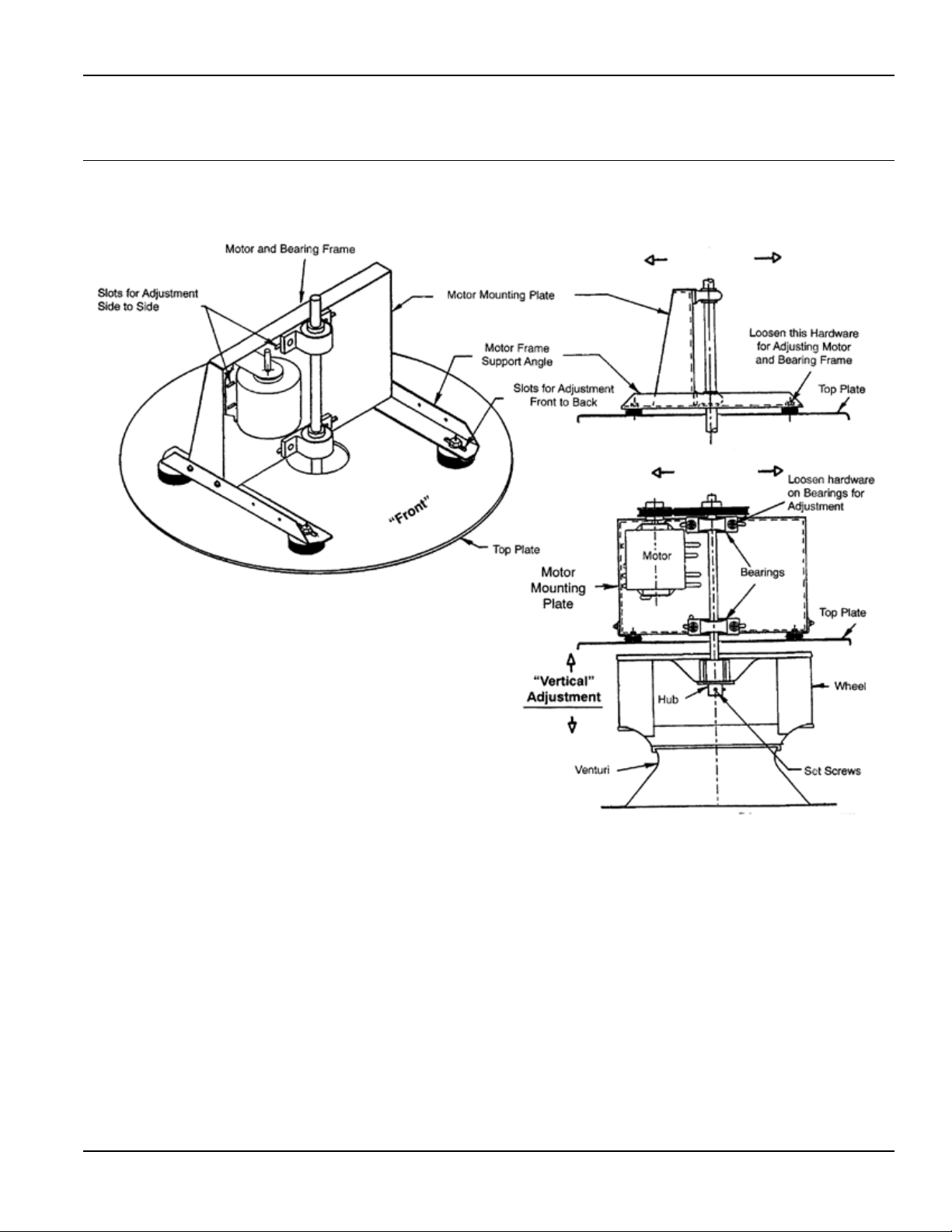
a. Check rotating components
for adequate clearance (wheel align-ment pr
cedures are on page 7) and direction of rota-
tion. CCW looking from drive side.
b. Check proper belt tension and pulley
alignment.
c. Check installation and anchoring.
d. Check fan bearings.
Switch on electrical supply and allow fan to
reach full speed.
Check carefully for Correct rotation of the
centrifugal wheel.
Incorrect rotation
overloads motor
severely and results in serious motor dam-
age. To change rotation of three phase
units, interchange any 2 of the 3 line leads.
On single phase units, change the terminal
block set-up following the wiring diagram on
the motor.