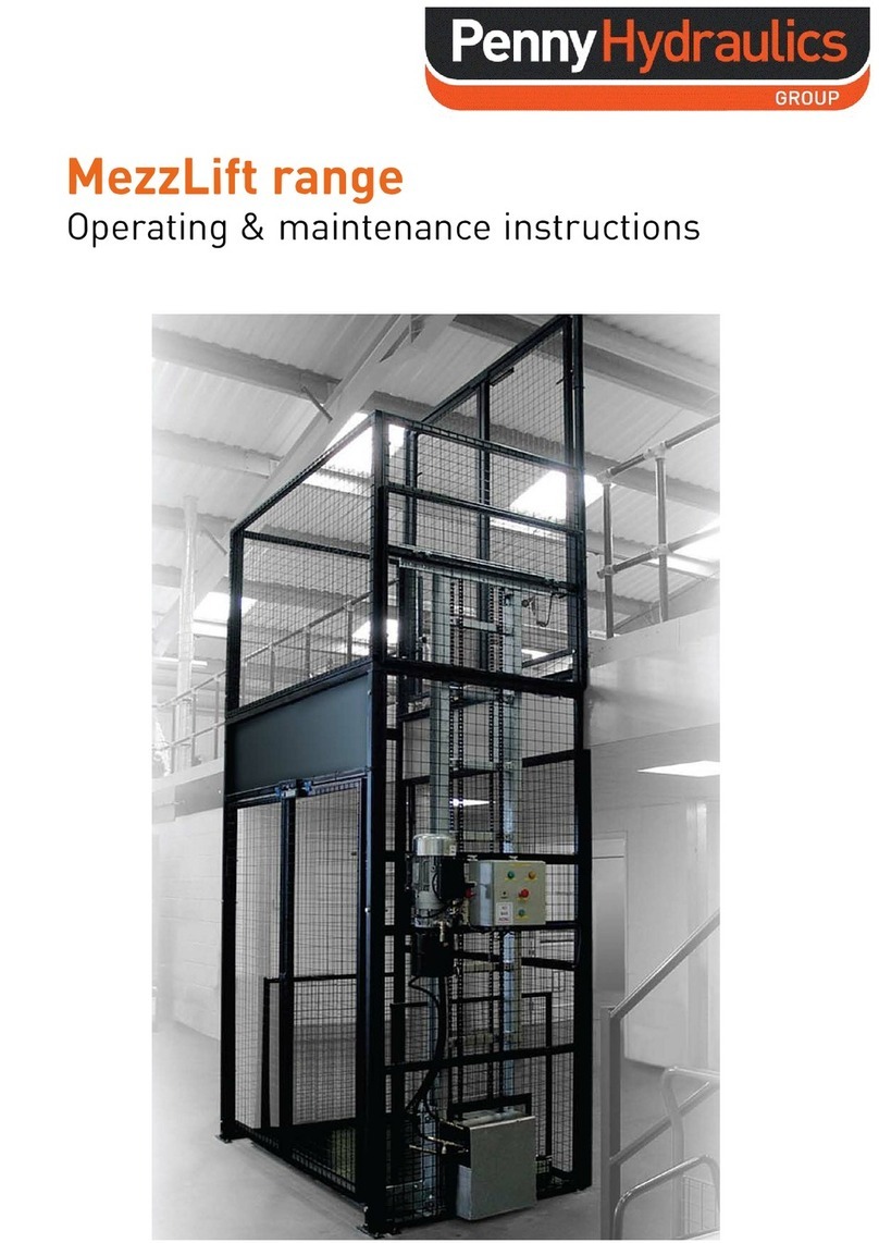
PennyHydraulics LoadLift range Installation and operation manual


LoadLift
Operating and Maintenance Instructions
Station Road
Clowne
Chesterfield
Derbyshire
S43 4AB
Tel: 01246 811475
Fax: 01246 810403
E-mail: sales@pennyhydraulics.com
Website: www.pennyhydraulics.com

2
Safety Warning
In the interest of safety, all personnel involved in the operation of the LoadLift must
read and understand this operation manual. If they do not then they must not operate
the equipment.
•Before any operation, check that the relevant documentation is available, in order and
current.
•As a minimum statutory requirement the LoadLift should be thoroughly examined
every six months by a competent person. See “Maintenance” in this manual for full
Statutory responsibilities.
•The LoadLift must not be overloaded. Refer to the safe working load signs attached
to the equipment.
•The LoadLift must only be operated by trained and competent personnel. Training is
offered by Penny Hydraulics and a training register is included at the back of this
manual.
•During operation of the LoadLift, access to the area should be restricted to those
personnel essential to the operation only.
•Do not leave any load suspended between lifting / lowering operations.
•All safety notices must be adhered to at all times.
•Never interfere with the unit. It should run smoothly at all times, if in doubt call the
HELPLINE telephone number 01246 811475.
•Keep the LoadLift properly maintained by a competent person. See the
“Maintenance” section in this manual.
•Do not adjust or interfere with any factory settings.
•Isolate and immobilize the equipment before commencing any maintenance routine.
Do not modify or re-install this machine without seeking guidance from
Penny Hydraulics Ltd

3
CONTENTS
Page
2. Safety Warning
3. Contents
4. Introduction
5. Operation
6. Fault Finding
7. Warranty Policy
8. Maintenance, Recommended Spares, Recommended Lubricants
9. Statutory Obligations
11. Service Contract
12. Technical Data
14. Declaration of Conformity
15. Signs
17. Parts List
18. Electrical Schematic
20. Training Register
21. Work Record

4
Introduction
Thank you for purchasing a Penny Hydraulics LoadLift.
The LoadLift is a vehicle mounted loading platform designed and manufactured at our
factory in Clowne, Chesterfield to safely lift loads of up to 350kg., subject to model type It
can also be adapted for use in fixed and static applications.
Operation is by fail safe, pendant pushbutton control. All functions are protected by inbuilt
overload features.
These operating instructions tell you what you need to know about its operation along with
guidance on safety and general care, please study them carefully.
Due to our company’s policy of continuous improvement, the following descriptions and
illustrations used in this manual and parts book are without prejudice. We reserve the right
to make alterations in order to increase the performance of our product, or for any other
reason. We are not obliged to alter these instructions accordingly. These instructions do
not assert to be complete
Load Lift
© This document is the property of Penny Hydraulics Limited and must not be copied or
amended in part or in whole unless prior, express written permission is obtained from the
Company

5
Method of Operation
1) Before operation, please read the operating instructions and ensure all persons
involved in the lift are familiar with the equipment and local requirements.
2) Ensure the vehicle is on firm and level ground with the handbrake applied and wheel
chocks deployed where necessary.
3) Switch on the LoadLift isolating switch located on the control panel.
4) Before operating check for potential hazards, in particular around the area where the
platform will land.
5) Check the unit visually for signs of defects.
6) Release the platform locking latches and extend the platform.
7) Check the area is clear and from a safe position, use the push button control to
position the
platform at either the top for unloading or bottom for loading operations.
8) Place the load on the platform as centrally as possible.
9) Raise or lower the load using the push button control taking care to observe and
monitor the
equipment for malfunction or interference. Keep clear of the moving components at
all times.
10) On completion of the loading / unloading operations, raise the LoadLift into the
transport position, fold the platform and secure with the latches.
11) Switch off the LoadLift isolating switch.
12) Always double check that the platform is securely stored and locked in position and
the isolating switch in the cab is off before driving the vehicle.

6
Fault Finding
FAULT CAUSE RECTIFY
System Will Not Energize
When Isolator Is Switched
On
Faulty Earth
Faulty Supply From Battery
Check Earth Connections,
Clean And Re Make.
Check Fuses And Replace If
Necessary
System Energizes But Lift
Will Not Operate
Faulty Supply From Control
Box
Faulty Earth At Control Box
Check 5A Fuses And
Replace If Necessary
Check Earth Connection At
Control Box, Clean And Re
Make
Power Pack Energizes But
Lift Will Not Raise
Overload On Platform
Low Oil Level In Power Pack
Reduce Load
Top Up Oil Level
Power Pack Energizes But
Lift Raises Slowly
Overload On Platform
Low Oil Level In Power Pack
Faulty Power Pack
Reduce Load
Top Up Oil Level
Replace Power Pack

7
Penny Hydraulics Limited Warranty Policy
This Policy is intended to provide our customers with the best possible support to ensure
trouble free use of their new Penny Hydraulics lifting equipment.
Products sold by the Company are guaranteed to be free from defective material and
workmanship for a period of one year from the date of invoice or from the date of the
commissioning certificate.
This warranty applies only under the following conditions:
a) The unit or part must not have been subject to neglect or abuse, or operated under
abnormal conditions or in an unapproved application.
b) The responsibility of the Company is restricted to what is, in their judgement an
adequate repair or replacement of the Company’s product.
c) An authorised engineer must carry out a six monthly inspection.
d) The warranty is void if examination reveals that the unit or part has been repaired or
adjusted other than by an authorised engineer.
e) Normal service repairs carried out by authorised engineers are supported by their
own warranty.
f) Warranty does not extend to consumable items requiring replacement due to normal
wear and tear.
Any claim under warranty must be made in the first instance by contacting Penny Hydraulics
The decision will then be made on how best to proceed after consultation with the customer.
UK Mainland
We will normally have one of our own engineers based around the country visit the site to
rectify the problem. This policy may be varied at our discretion but it is our aim to give the
very best possible response to minimize product downtime and inconvenience.
Other Locations
Warranty is limited to a parts only service but in certain areas we have service partners who
may be able to assist. Any defective item should be returned to Penny Hydraulics Ltd for
inspection and any valid warranty claim will include reasonable carriage costs both ways. A
replacement part will then be sent to the customer.
No variation of the warranty as stated in the Company’s Standard Terms and Conditions of
Sale is authorised unless agreed in writing by a Director of the Company. This is the only
warranty given and the Company accepts no other responsibility.

8
Maintenance
Your LoadLift is subject to the LIFTING OPERATIONS AND LIFTING EQUIPMENT
(LOLER) regulations 1998 which is a statutory requirement to record on a formal document,
the safe working condition of the LoadLift, attachments and mounting structure.
Penny Hydraulics Ltd. Support Team offers a service package to meet customer
requirements and conform to LOLER certification. Please see Service Contract form
enclosed.
The following Planned Maintenance Schedule is designed to monitor the safe working order
of the LoadLift and includes a Thorough Examination by a Competent Person required by
LOLER.
LOLER also requires that a Thorough Examination is carried out following any exceptional
circumstance that may affect the safety of the equipment.
Any defects found whilst carrying out the Planned Maintenance Schedule must be reported
and recorded and the equipment taken out of operation until action by a Competent Person
is undertaken.
The Planned Maintenance Schedule may require the use of parts and consumables.
A list of recommended spares and lubricants is attached.
Planned Maintenance Schedule
On receipt of a new machine and before it is put into service, check that there is no transit
damage or evidence of mishandling.
Before any work is undertaken, ensure the site supervisor is informed and that all safety
precautions are observed and adhered to.
Pay attention to site specific safety and PPE requirements.
Unless dynamic checks, tests or setting up procedures are being carried out, always isolate
the machine from the power supply.
Where dynamic checks are being performed, it is advisable to appoint an assistant to be
available on request.
Ensure a clean working area and sufficient cleaning materials.
Ensure the work area is cordoned off, paying particular attention to the sweep areas
required for dynamic testing.
Daily / Before Use.
1) Check visually for signs of external damage.
2) Check all guards are securely in place.
3) Check for loose or missing nuts, bolts and fasteners.
4) Check for external oil leaks.
5) If any leaks are evident, check the hydraulic oil level.

9
6) Check for damage to electrical cables and connectors
Weekly.
1) Check all as for Daily.
2) Thoroughly clean the support structure and check the security of the interface with
the vehicle.
6 Monthly.
The 6 monthly Thorough Examination is a statutory requirement to conform with
LOLER regulations for lifts carrying persons and must be carried out by a
Competent Person who must sign the relevant documentation.
1) Check all as for Daily, Weekly.
2) Thoroughly examine the main structures and sub frames for soundness and signs of
deflection.
3) Thoroughly inspect all welds.
4) Thoroughly check the security of all fixings on the main body and sub frames.
5) Thoroughly examine all pivot points for excessive play. Remove the pivot pins and
thoroughly inspect the condition of the pins, bearings and linkages and replace where
necessary.
6) Thoroughly examine all electrical components, cables and connectors.
7) Replace the hydraulic oil in the power pack.
Load Test
It is recommended that a load test is carried out as part of the Thorough Examination to
assess the integrity of the LoadLift and its supporting structures.
Any defects or signs of potential failure must be rectified before the machine is allowed back
into service.
Method
1) Prepare the vehicle for operation in a safe working area, with the brakes firmly
applied and cordon off with appropriate barriers and work in progress signs.
2) Prepare the maximum prescribed test weights as determined by the LoadLift model
number.
3) Clear the site and admit power.
4) Without load, operate the LoadLift through its full extent to ensure correct operation.
5) Place the test load centrally on the platform and raise and lower to its full extents as
before.
6) Check for signs of excessive flexing, structural deformation, paint flaking and
excessive play in the joints.
On completion of the tests, restore the vehicle to its normal driving position, restore the
working area and complete the necessary documentation.

10
Overload Test
An overload test is carried out on all new LoadLift at the factory and forms part of the test
certificate requirements.
If the LoadLift is fitted to the vehicle by Penny Hydraulics Ltd. or one of its authorized
dealers, the system, including the sub structure and vehicle interface, will be Overload
Tested as part of the test procedure.
An Overload Test must be carried out if:
1) The LoadLift is fitted to a new or modified structure.
2) Any Modifications have been carried out to the LoadLift or support structure.
3) Following any incident which may have caused damage to the LoadLift or its
supporting structure.
To carry out an Overload Test, elements of the system protection features have to be
overridden and therefore must only be carried out by a competent person.
In severe or extreme conditions, it is recommended that an Overload Test is incorporated
into the Annual Load Test of LoadLift and its supporting structure
Please contact Penny Hydraulics Ltd. for further information.

11
Service Contract
Date
Lift location
Post code
Contact
Telephone
Email
Invoice address
Post code
Contact
Telephone
Email
Penny Hydraulics Ltd agrees to carry out one annual service and one interim inspection on
the lift in any twelve-month period. A test certificate will be left on site and a copy sent with
the invoice.
In the event of a problem arising in-between scheduled visits the customer should telephone
the Helpline on 01246 811475 as soon as possible so that appropriate action can be taken
by us. There will be no charge for the call-out or for labour unless the problem is due to
abuse or misuse. Parts may be added to the next invoice due.
The customer will be invoiced following each visit and by signing this document agrees to
make full payment within 30 days of the invoice date in accordance with the agreed scale of
charges, which may vary from time to time. This service contract will continue until
cancelled in writing by either party.
Signed: ………………………………… Print name: ………………………..
Position: ………………………………. Order number: ……………………..
More details are available online.
Please fax, post or email this form to the office below.
Penny Hydraulics Ltd
Tel 0044 (0) 1246 811475
Fax 0044 (0) 1246 810403
Email [email protected]
Web www.pennyhydraulics.com

12
Technical Data
General Dimensions / Loading Chart
Dimensions Will Vary Subject To Model Type
Power Supply
Standard LoadLifts require a 12volt (24V Optional) DC electrical supply. Any circuit
breakers employed in the system must be of a type that can cope with the surge of the
electric motor.
Electrical Specification
12 volts DC 40A
24 volt optional
240 volt – contact Penny Hydraulics Ltd.
Typical Weights
Standard LoadLift 100kg subject to specification.
Maximum Safe Working Load
Each LoadLift 250 is marked individually with its Maximum Working Load.

13
Noise Levels
A survey sheet giving full details is available on request. Briefly, the results are as follows: -
Power Pack Running 65dB(A)
These levels are well below those at which hearing can be damaged and below levels at
which action is required under the noise at work regulations.
COSHH
Terminal Disposal
Penny Hydraulics will remove and dispose of the entire lift in an environmentally sound
manner when required.

14
EC DECLARATION OF CONFORMITY
This declaration relates exclusively to the machinery in the state in which it was supplied,
and excludes components, which are added, and/or operations carried out subsequently by
the final user.
We Penny Hydraulics Limited
Station Road Industrial Estate, Station Road, Clowne, S43 4AB.
Hereby declare that the product(s) listed below: -
Model:
Load
Lift Series
Serial No.
Conforms to the essential requirements of 2008 / 1597, The Supply of Machinery (Safety)
Regulations 2008 and the following Directives, Standards and other Normative Documents
where appropriate.
EU Directives/Regulations
Machinery Directive 2006/42/EC
Electrical Equipment (Safety) Regulations 1994
European Council EMC Directive 89/336/EEC
Standard(s)
BS EN 12999 Cranes, Loader Cranes,
BS 7121 Parts 1,2 and 4
BS EN 982 Safety of Machinery
EN 50081-1: 1997; Electromagnetic Compatibility, General
Standard
Radiated RF Emissions Class B (30MHz – 300MHz)
Normative Documents
DIN 15018 Steel Structures
BS 2573 Rules for design
The Lifting Operations and Lifting Equipment Regulations
1998.
The Provision and Use of Work Equipment Regulations 1998.
All information is given within a Technical File compiled by: Mr Terry Brocklehurst
c/o Penny Hydraulics Ltd.
Place: - Penny Hydraulics Limited Signature: -
Date: - Full Name: - J. D. Penny
Position: - M.D.
BS EN ISO 9001: 2000 British Standards Institute Registered Company
Certificate No. FM 20203

15
Signs
Read the Manual
Refer to the Manual
Caution
ON / OFF
RAISE
LOWER
RAISE
LOWER

16
Recommended Spares
Recommended Lubricants
DUTY LUBRICANT SPECIFICATION
Hydraulic Power Pack Mineral Hydraulic Oil HM32
General Lubrication Grease LEP2
Description Part No. Qty.
5A Fuse Assembly 090-000001 2
125A Fuse Assembly 090-000003 2
539-000019 Pin Assembly - Lift Ram - 100mm 1
539-000020 Pin Assembly - Lift Ram - 110mm 1

17
ALWAYS CONFIRM MODEL AND
SERIAL NUMBER WHEN
ORDERING SPARE PARTS

18
Electrical Schematic Circuit Diagram
Table of contents
Other PennyHydraulics Lifting System manuals
Popular Lifting System manuals by other brands

Meganex
Meganex MEG30 instruction manual

GL-Tech
GL-Tech BOAT LIFT manual

Liko
Liko Golvo 7000 Series Service manual

Endres
Endres AKKULIFT STANDARD operating instructions

AMF-BRUNS
AMF-BRUNS BSL 350 Short operation manual

JH Industries
JH Industries Copperloy EDGE-OF-DOCK SEL Series Installation & owner's manual