PENTAGAST cookmax BCS930ILL User manual

cookmax ist eine Marke der PENTAGAST eG
Ruhrstrauch 4 D-36100 Petersberg
Tel: +49 (0) 66 1 / 93 48 3 –0 Fax: +49 (0) 66 1 / 93 48 3 - 25
www.pentagast.de
Lüftung
Wandhaube in Schrägform
Artikel-Nr.
313021 (BCS930ILL)
Handbuch

CAPPE ASPIRANTI
I T
DUNSTABZUGSHAUBEN
DE
EXTRACTION HOODS
GB
Modelli :
- SNACK
- SNACK VENTIL
- LINE
- LINE VENTIL
- CUBIC
- CUBIC VENTIL
- FORNI-ÖFEN-OVEN
- LAVASTOVIGLIE-SPÜLMASCHINEN-DISHWASHER
- INDUZIONE-INDIKTION-INDUCTION
SCHEMI INSTALLAZIONE / INSTALLATION DIAGRAM
pagina 3-5
ISTRUZIONI PER L'INSTALLATORE USO E MANUTENZIONE
pagina 6-9
AUFSTELLUNGS-, GEBRAUCHS- UND INSTANDHALTUNGS-ANWEISUNGEN
pagina 10-14
INSTRUCTIONS FOR INSTALLATION, ADJUSTMENT, USE AND MAINTENANCE
pagina 15-18
Read the manual
thoroughly and keep it
in a safe place
throughout the product's
service life.
Read the warning
notes immediately!
Leggere attentamente il
libretto e conservarlo
con cura per tutta la
durata del prodotto.
Leggere subito le
avvertenze!
Bitte die Geräteanleitung
aufmerksam lesen und für
die ganze Gerätedauer
sorgfältig aufbewahren
Bitte die Anleitung
sofort durchlesen!
GRX 1 1 / 18

I T
INDICE
SCHEMI INSTALLAZIONE
1-FISSAGGIO A SOFFITTO
pagina 3
2-FISSAGGIO A MURO
pagina 3-4
ISTRUZIONI PER L’INSTALLAZIONE
.
1-CONFORMITÁ ALLE NORME E LEGGI
pagina 6
2-GENERALITA'
pagina 6
3-POSIZIONAMENTO
pagina 6
4-MONTAGGIO
pagina 6-7
5-COLLEGAMENTI ELETTRICI
pagina 7
6-VERIFICA FUNZIONALE
pagina 8
ISTRUZIONI PER L’UTENTE
1-AVVERTENZE GENERALI
pagina 9
2-PANNELLO DI CONTROLLO
pagina 9
3-PULIZIA E MANUTENZIONE
pagina 9
GRX 1 2 / 18

SCHEMI DI INSTALLAZIONE - INSTALLATIONSCHEMEN I T
1-FISSAGGIO A SOFFITTO - DECKENMONTAGE
Fig.1 Fig.2
A – Tassello / Dübel / Expansion bolt A – Tassello / Dübel / Expansion bolt
B – Dado M8 / M8 Mutter / M8 Nut B – Golfare / Ringschraube / Eye bolt
C – Barra filettata M8 / Threaded bar M8 C – Moschettone / Haken / Joint
D – Tubo copri barra Inox Ø12 mm / Schutz-Stahlrohr für Stab Ø12 mm
D – Tenditore / Spanner / Eccentric clamp
Ø12 mm Stainless Steel pipe E – Catena / Kette / Chain
E – Rondella / Unterlegscheibe / Washer F - Rondella / Unterlegscheibe / Washer
2-FISSAGGIO A MURO - WANDMONTAGE
Fig.3
GRX 1 3 / 18

SCHEMI DI INSTALLAZIONE - INSTALLATIONSCHEMEN I T
Fig.4
Fig.5 Fig.6
Fig.7 Fig.8
GRX 1 4 / 18

SCHEMI DI INSTALLAZIONE - INSTALLATIONSCHEMEN I T
Fig.9
Fig.10
GRX 1 5 / 18

ISTRUZIONI PER L'INSTALLAZIONE I T
1-CONFORMITÁ ALLE NORME E LEGGI
2 GENERALITA’
3. POSIZIONAMENTO
4. MONTAGGIO
Qualora il solaio sia costruito con laterizi vuoti si possono utilizzare i tasselli chimici a fiala. Per le operazioni di
montaggio seguire e le indicazioni seguenti.
II montaggio della cappa può essere eseguito utilizzando i tasselli e i golfari .
Risulta particolarmente importante accertarsi che il soffitto , o la parete , siano adatti a sopportare il peso della
cappa; altrimenti sarà da far eseguire le dovute opere murarie di rinforzo.
- I’area perimetrale della cappa deve debordare di almeno 20 cm rispetto all’area degli apparecchi e comunque tale
valore va verificato con le normative locali vigenti.
- I’altezza dal pavimento del bordo inferiore frontale consigliata è di 2000 mm;
- deve essere collegata ad un camino di sicura efficienza oppure direttamente all’esterno;
Le cappe a parete serie Cubice Line DEVONO essere montate con la zona aspirante dalla parte della parete; mentre
le cappe serie Forni e Lavastoviglie DEVONO essere montate con la zona aspirante posta sul fronte .
Attenzione
Livello di rumorosità: Le cappe con motore incorporato hanno un’emissione di rumorosità non superiore a 70 dB(A)
• Rubinetto di scarico grassi
- Su richiesta è fornibile un filtro a labirinto in acciaio inox 304delle stesse dimensioni conforme alla normativa DIN
18869-5 ;
• La cappa deve essere posizionata nel rispetto dei seguenti parametri:
•
Rimuovere molto lentamente la pellicola protettiva dei pannelli esterni, senza strapparla per evitare che rimanga
attaccato il collante. Qualora ciò accadesse, togliere i residui di colla usando solventi appropriati.
• Per le cappe con ventilatore incorporato è possibile l’accoppiamento ad un regolatore di velocità specifico da montare
esternamente se non previsto già montato sulla cappa .
• Le cappe vengono fornite complete di filtri e pannelli di tamponamento,alcuni modelli con lampade al neon di
illuminazione 220V 50 Hz ma prive di aspiratore , tranne la serie con ventilatore incorporato la quale prevede
ventilatore 220 V (1) 50 Hz.
- Il filtro standard è un filtro a labirinto in acciaio inox 304 dim 400x500x25
• I filtri montati sulle cappe possono essere di 2 tipologie completamente intercambiabili:
La tipologia di regolatore andrà determinata a seconda dei motori presenti sulla cappa .
- Norme di igiene locali.
- Legge 5 marzo 1990, n. 46 - Norme per la sicurezza degli impianti elettrici e gas.
- Norma UNI-CIO 8723 - Prescrizioni di sicurezza per gli impianti a gas delle cucine.
L’installazione deve essere eseguita da personale professionalmente qualificato secondo le norme locali in vigore. In
particolare si richiamano:
GRX 1 6 / 18

I T
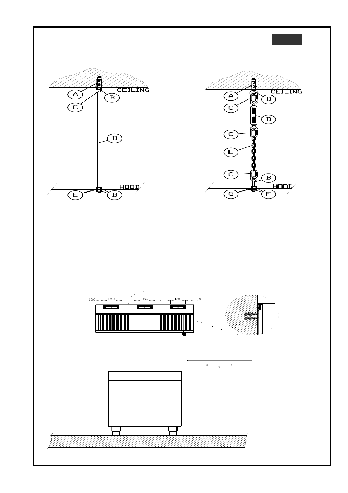
- Avvitare a fondo le barre filettate direttamente ai tasselli montati sul soffitto
- Bloccare con rondella e dado, montare i tubi copribarra
b) Montaggio con catena (fig. 2)
- Avvitare a fondo i golfari Ø 8 MA ai tasselli sul soffitto;
- collegare le varie coppie di golfari mediante catene , moschettoni e tenditori .
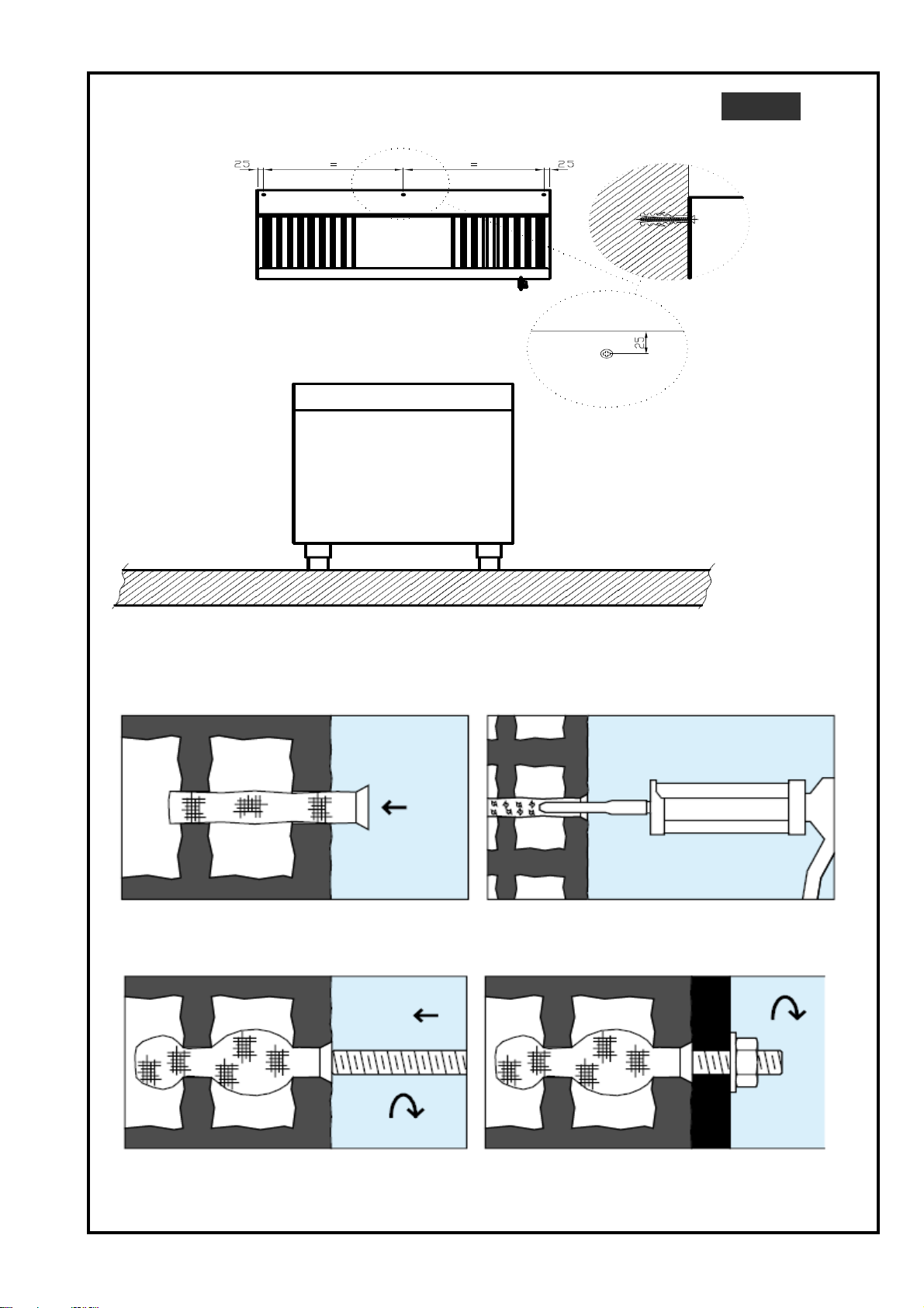
4.2 Montaggio della cappa con tassello chimico a fiala ( fig.5-8 )
- Effettuare nei punti di ancoraggio un foro da 14 mm con profondità minima di 100 mm;
- innestare nei fori l’involucro a rete (fig. 5 ),
- inserire il beccuccio della pistola e poi, iniettare il prodotto all’interno dell’involucro ( fig. 6 )
Nota: Per il montaggio con tassello chimico seguire le istruzioni riportate sulla confezione del tassello stesso.
4.3 Montaggio delle cappe a parete (fig. 3-4)
5. COLLEGAMENTI ELETTRICI
Collegamento lampade di illuminazione
Tutte le nostre cappe , tranne quelle per forni e lavastoviglie , sono dotate o possono esserlo di illuminazione .
Tutte le lampade vanno alimentate alla tensione di 220 V (1) 50 Hz.
La potenza installata dipende dalla grandezza della cappa ( potenza massima con nostre cappe standard 1,5 Kw ).
Collegamento di terra :
Collegare la cappa ad un efficace presa di terra ed includerle in un sistema equipotenziale.
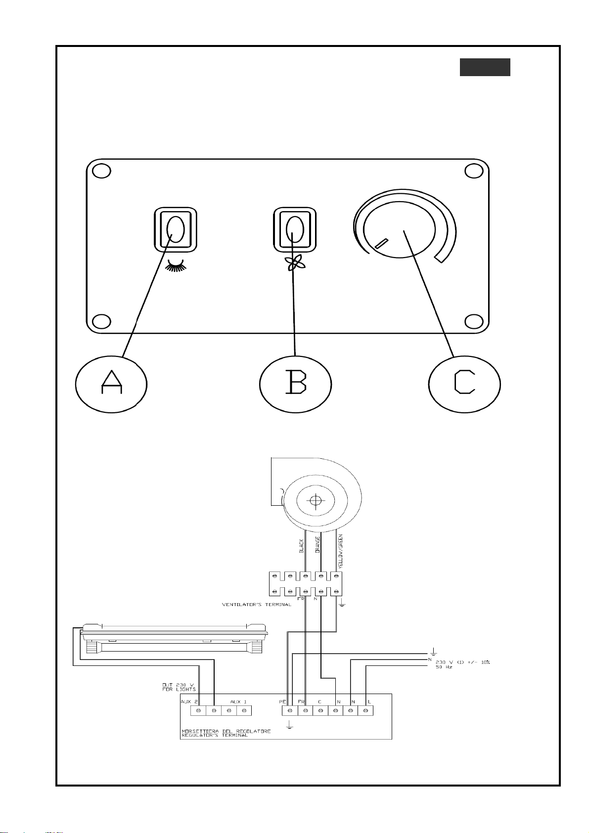
Collegamento del regolatore di velocità ( Fig.10 )
II variatore di velocità non fa parte della dotazione di serie della cappa tranne che per i modelli che ne prevedono il
montaggio all’interno .
- attendere che la schiumatura si raffreddi (circa 6 minuti con temperatura ambiente di 20 °C) e innestare a pressione il
tassello;
attendere che il componente abbia fatto presa (circa 1 ora con temperatura ambiente a 20 °C) e poi completare il
montaggio avvitando sul tassello la barra filettata o la fune ( fig 7 e fig. 8 )
Le cappe a parete vanno fissate al soffitto secondo le indicazioni già indicate, mentre per il fissaggio alla parete
verticale si utilizzano i tasselli meccanici o chimici a seconda della tipologia di parete . Alcune cappe prevedono il
montaggio facilitato essendo fornite con tre supporti che vanno fissati preventivamente alla parete e sui quali si
aggancia la cappa (fig. 3). Altre tipologie prevedono il fissaggio diretto della cappa alla parete dopo aver posizionato i
vari tasselli a muro ( fig. 4 ).
La gamma con illuminazione premontata , prevede anche il cablaggio con cavo elettrico lunghezza libera di circa 1 m
all’uscita della cappa o di una scatola di derivazione con morsettiera per rendere molto più facile all’impiantista il
collegamento .
- Predisporre la lunghezza delle catene o in alternativa delle barre filettate e appendere la cappa al soffitto operando
come segue:
a) Montaggio con barre filettate ( fig. 1).
- Sollevare la cappa e posizionarla in modo che le barre entrino sui fori già predisposti sul bordo superiore della stessa
e infine bloccare con dadi e rondelle.
- montare un´altra serie di golfari direttamente sulla cappa utilizzando i fori già previsti sul bordo superiore o le
indicazioni fornite ;
4.1 Montaggio della cappa con tasselli
Per il montaggio procedere come segue:
- Segnare sul soffitto e sulla parete, con debiti riferimenti, i punti per il montaggio dei tasselli e forare con una punta di
Ø 14 mm.
- Innestare i tasselli M8 e poi svitare la vite dagli stessi.
GRX 1 7 / 18

I T
II cavo di collegamento dell’aspiratore deve essere del tipo antifiamma di sezione minima 3x1,5 mm2
Tensione alimentazione 220 V (1) 50 Hz , potenza massima pilotabile 900 W
6.VERIFICA FUNZIONALE DELL'IMPIANTO
• Mettere in funzione la cappa e gli apparecchi complementari.
• Controllare l’efficacia del sistema di evacuazione con una taratura generale secondo i dati di progetto.
• Addestrare l’utente in modo che prenda familiarità con l’uso degli apparecchi di comando e controllo
II variatore andrà posizionato in un punto facilmente accessibile , comodo per la manovra e lontano da fonti ci calore in
modo da favorire lo smaltimento del calore da esso prodotto .
Deve essere collegato al motore o ai motori secondo le indicazioni riportate nello schema elettrico allegato allo stesso
( Fig. 10 ).
A monte del variatore di velocità deve essere installato un interruttore di protezione onnipolare di portata adeguata
all’assorbimento massimo
Per gli altri modelli con ventilatore incorporato , viene fornito come accessorio su richiesta e ne risulta molto
importante la sua precisa identificazione in funzione della potenza del motore o dei motori che il regolatore dovrà
pilotare.
GRX 1 8 / 18

ISTRUZIONI PER L'UTENTE I T
1. AVVERTENZE GENERALI
• L’installazione deve essere effettuata secondo le istruzioni del costruttore da personale professionalmente qualificato.
2. PANNELLO COMANDI DEL VARIATORE DI VELOCITA'
( Fig. 9 )
3. PULIZIA E MANUTENZIONE
• Disattivare l’apparecchiatura in caso di guasto o di cattivo funzionamento. Per l’eventuale riparazione rivolgersi
solamente ad un centro di assistenza tecnica autorizzato dal costruttore e richiedere l’utilizzo di ricambi originali.
• Leggere attentamente il presente libretto in quanto fornisce importanti indicazioni riguardanti la sicurezza
d’installazione, d’uso e di manutenzione.
Conservare con cura questo libretto per ogni ulteriore consultazione dei vari operatori.
II mancato rispetto di quanto sopra può compromettere la sicurezza dell’apparecchiatura.
A - Interruttore lampade di illuminazione cappa con spia
B - Interruttore aspirazione con spia
C – Potenziometro regolatore di velocità
Nota: Nel caso in cui entrambe le spie siano spente è necessario verificare la presenza di tensione e il
controllo del fusibile interno al regolatore . Se il difetto persiste rivolgersi ad un tecnico qualificato.
• Una cappa aspirante è un apparecchio la cui funzione consiste nel “catturare” I’aria contenente grassi e odori
proveniente dalle apparecchiature di cottura. La cappa deve dunque essere sottoposta a regolari interventi di pulizia,
indicati di seguito, allo scopo di ottemperare ai requisiti igienici che le cucine moderne sono chiamate a soddisfare.
• Disinserire sempre l’alimentazione elettrica prima di eseguire qualsiasi operazione di pulizia o di manutenzione.
• Ogni settimana togliere i filtri antigrasso dalla cappa (ad esclusione delle cappe che non prevedono filtri ) e metterli
in acqua calda miscelata con soda oppure utilizzare una lancia di lavaggio con detersivo. Se necessario, impiegare
una morbida spazzola da stoviglie. Dopo aver lavato i filtri, risciacquarli in acqua calda, scuoterli bene e lasciarli a
sgocciolare ed asciugare un pò prima di rimetterli nella loro sede nella cappa.
Attenzione: I’accumulo di grasso all’interno del filtro può comportare pericolo d’incendio oltre a un cattivo
funzionamento della cappa. E’ importante quindi che i filtri vengano puliti accuratamente e frequentemente.
• Pulire le superfici in acciaio inox con acqua tiepida saponata quindi risciacquare abbondantemente ed asciugare con
cura.
Attenzione: Non utilizzare per la pulizia dell’acciaio prodotti contenenti sostanze corrosive (varecchina, acido cloridrico,
ecc.) anche se diluite; nonché di trucioli, paglietta, spazzole o raschietti d’acciaio comune.
• Pulire almeno due volte l’anno i condotti che collegano la cappa al camino esterno.
• Fare sottoporre l’impianto periodicamente (almeno una volta all’anno) ad un controllo totale. A tale scopo si
raccomanda la stipula di un contratto di manutenzione.
Lunga inattività dell’impianto
Durante i periodi di lunga inattività osservare le seguenti precauzlonl:
- disinserire l’alimentazione elettrica;
- pulire a fondo tutte le superfici di acciaio;
- passare energicamente su tutte le superfici in acciaio inox un panno appena imbevuto di olio di vaselina in modo da
stendere un velo protettivo;
- arieggiare periodicamente i locali.
GRX 1 9 / 18

DE
INHALTSVERZEICHNIS
INSTALLATIONSCHEMEN
1-DECKENMONTAGE
Seite 3
2-WANDMONTAGE
Seiten 3-4
ANLEITUNGEN FÜR DIE INSTALLATION
1-GESETZLICHE VORSCHRIFTEN UND TECHNISCHE NORMEN
Seite 11
2- ALLGEMEIN
Seite 11
3-AUFSTELLUNG
Seite 11
4-MONTAGE
Seiten 12
5-ELEKTRISCHER ANSCHLUSS
Seite 13
6-FUNKTIONSPRÜFUNG DER ANLAGE
Seite 13
GEBRAUCHSANLEITUNGEN
1-ALLGEMEINE HINWEISE
Seite 14
2- BEDIENUNGSPANEEL
Seite 14
3-REINIGUNG UND WARTUNG
Seite 14
GRX 1 10 / 18

ANLEITUNGEN FÜR DIE INSTALLATION DE
1-GESETZLICHE VORSCHRIFTEN UND TECHNISCHE NORMEN
2. ALLGEMEIN
3. AUFSTELLUNG
Die Aufstellung des Geräts muß vom qualifiziertem Fachpersonal, gemäß den aktuellen Sicherheitsvorschriften,
durchgeführt werden, insbesondere:
- Norm UNI-CIO 8723 - Sicherheitsvorschriften für die Gas-Anlagen der Großküchen.
- Gesetz 5 März 1990, nr. 46 - Vorschriften für die Sicherheit der Elektro- und Gasanlagen.
- Lokale Hygienevorschriften
• Die Dunstabzugshauben werden serienmäßig mit Fettfilter und Abdichtungspaneelen geliefert; einige Modelle werden
mit Neon-Lampen 220V 50 Hz aber ohne Absauggerät geliefert. Die Serie mit eingebautem Absauggerät ist mit einem
Abluftventilator 220 V (1) 50 Hz ausgestattet.
• Die Modelle mit eingebautem Absauggerät können an einem spezifischen Geschwindigkeitsregler angeschlossen
werden, der extern eingebaut werden muß, wenn nicht in der Dunstabzugshaube vorgesehen.
Der Typ des Reglers muß je nach dem eingebauten Antrieb gewählt werden.
•Die eingebauten Filter sind von zwei verschiedenen Typen, voneinander komplett austauschbar.
-Der Standard-Filter ist ein Edelstahl 304-Labyrinth-Filter, Abmessungen 400x500x25
- Auf Anfrage kann ein anderer Edelstahl 304-Labyrinth-Filter mit selber Abmaße geliefert werden, gemäß der
Richtllinie DIN 18869-5;
• Fettablasshahn
Geräuschpegel: Die Dunstabzugshauben mit eingebautem Antrieb haben einen Geräuschpegel nicht höher als
70 dB(A)
• Die Schutzfolie von den Paneelen langsam abziehen. Eventuelle Rückstände des Klebers können mit einem
geeigneten Lösungsmittel entfernt werden.
• Für die Montage der Dunstabzugshauben muß auf Folgendes geachtet weden:
Die Wand-Dunstabzugshauben Serie Cubice Line MÜSSEN mit dem Abluftbereich gegen die Wand montiert werden;
die Dunstabzugshauben der Serie Öfen und Spülmaschinen MÜSSEN mit dem Abluftbereich an der Vorderseite
aufgestellt werden.
- die Haube muß an einem effizientem externen Kamin verbunden werden oder direkt ins Freie;
- der empfohlene Abstand von der unteren Vorderseite der Haube zum Boden ist 2000 mm;
- die Verblendung der Haube muß mindestens 20 cm über den Bereich der Geräte laufen; jedenfalls muß dieser
Abstand den lokalen Regelungen angepasst sein.
ACHTUNG
GRX 1 11 / 18

DE
4. MONTAGE
- Die Gewindstäbe tief in die Dübel an der Decke anschrauben;
- Unterlegsscheibe und Mutter fest andrehen und die Rohrverkleidungen anbringen.
b) Montage mit Kette (Fig. 2)
- Die Ringschrauben Ø 8 MA tief in die Dübel an der Decke anschrauben;
- Die verschidenen Ringschrauben mittels Ketten, Haken und Spanner verbinden.
4.2 Montage der Dunstabzugshaube mit chemischen Dübeln ( Fig.5-8 )
- Die Positionen für die Verankerungen bohren: Durchmesser der Bohrlöcher 14 mm, Tiefe mindestens 100 mm.
- Die Netzhülle in die Bohrungen eindrücken (Fig. 5 ),
- Mit der Pistole das Mittel in die Netzhülle einspritzen ( Fig. 6 )
Anmerkung: bei Montage mit chemischen Dübeln müssen auch die Anleitungen des Dübels beachtet werden.
4.3 Wandmontage der Dunstabzugshauben (Fig. 3-4)
4.1 Montage der Dunstabzugshaube mit Dübel
Wie folgt vorgehen:
- An die Decke und an die Wand die Positionen für die Schrauben anzeichnen und Löcher mit Ø 14 mm bohren.
- Die Dübel M8 wandbündig eindrücken und die Schraube aufschrauben.
- Die Länge der Ketten oder Gewindestäbe vorbereiten und die Dunstabzugshaube an die Decke hängen. Wie folgt
vorgehen:
a) Montage mit Gewindestäbe ( Fig. 1).
-Gerät so einhängen, daß es fest an den vorgesehenen Aufhängungen einrastet und mit Unterlegsscheibe und Mutter
befestigen.
- Eine andere Serie von Ringschrauben direkt an der Dunstabzugshaube montieren, bei Verwendung der auf der
oberen Seite vorgesehenen Bohrungen, oder bei Beachtung der Anleitungen.
- Abwarten bis die Schäumung abgekühlt ist (ca. 6 Minuten bei Umgebungstemperatur von 20°C) und die Dübel
eindrücken.
Warten bis das Mittel haftet (ca. 1 Stunde mit Umgebungstemperatur bei 20 °C) und den Gewindestab oder den Seil in
die Dübel einschrauben ( Fig 7 und Fig. 8 )
Bei Deckenmontage müssen die Dunstabzugshauben an die Decke gehängt werden, wie in den Anleitungen bereits
beschrieben; bei vertikaler Wandmontage müssen die mechanischen oder chemischen Dübel verwendet werden, je
Um die Dunstabzugshaube zu montieren, können die Dübel und die Ringschrauben verwendet werden.
Im Falle, daß die Decke aus Ziegelsteinen gebaut ist, können Sie die chemischen Dübel verwenden. Für die Montage
beachten Sie bitte folgende Hinweise.
Die Wand oder die Decke müssen ausreichend tragfähig sein, andernfalls müssen sie verstärkt werden.
GRX 1 12 / 18

DE
5. ELEKTRISCHER ANSCHLUSS
Anschluss Lampen
Alle Lampen müssen mit einer Spannung von 220 V (1) 50 Hz versorgt werden.
Erdleitung:
Das Gerät an einer wirksamen Erdverbindung anschliessen und an einem Potentialausgleichsystem einbinden.
Anschluss des Geschwindigkeitsreglers ( Fig.10 )
Der Anschlusskabel des Sauggeräts muß flammhemmend sein, mit Mindestabschnitt 3x1,5 mm2.
Versorgungsspannung 220 V (1) 50 Hz , maximale steuerbare Leistung 900 W
6. FUNKTIONSPRÜFUNG DER ANLAGE
• Die Dunstabzugshaube und die zubehörigen Geräte in Betrieb setzen.
• Die Wirksamkeit des Abluftsystems mit allgemeinem Abgleich nach den Projekt-Werten überprüfen.
• Benutzer mit den Steuerungen und Prüfgeräte vertraut machen.
Die Modelle mit serienmäßiger Beleuchtung müssen an einem Kabel mit beliebiger Länge, ca. 1 Meter am Ausgang
der Dunstabzugshaube verkabelt werden, oder es soll eine Verteilerdose mit Klemmbrett vorgesehen werden, um dem
Fachpersonal die Anschlüsse zugänglicher zu machen.
Alle Dunstabzugshauben, bis zu den Modellen für Öfen und Spühlmaschinen, können mit Beleuchtung ausgestattet
werden oder sind mit Beleuchtung ausgestattet.
Der Geschwindigkeitsregler wird nicht serienmäßig geliefert, nur einige Modelle sind mit integriertem Regler
ausgestattet.
Die installierte Leistung hängt von der Größe der Dunstabzugshaube ab ( die maximale Leistung unserer Standard-
Dunstabzgshauben ist 1,5 Kw ).
Für die Modelle mit eingebautem Lüfter wir der Regler auf Anfrage montiert. Es ist sehr wichtig, daß der Regler an der
Stärke des zu steuernden Antriebs oder Antriebe genau angepasst wird.
Der Geschwindigkeitsregler muß an einem Punkt montiert werden, wo er leicht zugänglich und leicht gesteuert sein
kann; entfernt von Wärmequellen, damit die Wärme, die er erzeugt schnell entfernt wird.
Der Regler muß gemäß dem elektrischen Schema der beigelegten Bedienungsanleitungen (Fig. 10) angeschlossen
werden.
Stromaufwärts muß ein allpoliger Trennschalter installiert werden mit Stromfestigkeit der maximal aufgenommenen
Leistung anpassend.
GRX 1 13 / 18

GEBRAUCHSANLEITUNGEN DE
1. ALLGEMEINE HINWEISE
• Die Installation muß gemäß den Hinweisen des Herstellers vom qualifiziertem Fachpersonal durchgeführt werden.
2. BEDIENUNGSPANEEL DES GESCHWINDIGKEITSREGLERS
( Fig. 9 )
3. REINIGUNG UND WARTUNG
• Eine Dunstabzugshaube ist ein Gerät, das die Luft voll Fett und Gerüchen von den Kochgeräten ansaugt. Die
Dunstabzugshaube muß daher regelmäßig gereinigt werden, um den Hygiene-Richtlinien im Großküchenbereich zu
entsprechen. Nachstehend beschreiben wir im Einzelnen, wie das Gerät gereinigt werden muß.
• Gerät vor der Reinigung oder der Wartung immer vom Netz trennen.
• Bei der Haubenserie mit Filter müssen jede Woche die Fettfilter gereinigt werden. Weichen Sie die Fettfilter in
heißem Wasser mit Natriumkarbonat ein oder verwenden Sie eine Waschlanze mit Spülmittel. Verwenden Sie zur
Reinigung eine weiche Bürste und spülen Sie die Filter gut aus, schütteln Sie sie und lassen Sie die Filter abtropfen.
Kurz trocknen bevor sie wieder eingesetzt werden.
B – Schalter Luftansaugung mit Kontroll-Leuchte
C – Drehwiderstand Geschwindigkeitsreglers
Anmerkung: Im Falle, daß beide Kontrolleuchten ausgeschaltet sind, müssen Sie checken, ob das Gerät mit Strom
versorgt ist und die Schmelzsicherung überprüfen. Wenden Sie sich an qualifiziertes Fachpersonal falls der Fehler
nicht beseitigt werden kann.
Bewahren Sie die Anleitung für einen späteren Gebrauch oder für Nachbesitzer auf.
* Bei Störungsfällen ist das Gerät vom Netz zu trennen. Reparaturen darf nur eine konzessionierte Fachkraft
durchführen. Verlangen Sie Original-Ersatzteilen.
Die Nicht-Erfüllung obengenannter Voraussetzungen kann die Sicherheit des Gerätes beeinträchtigen.
A – Lichtschalter Dunstabzugshaube mit Kontroll-Leuchte
- auf alle Edelstahloberflächen eine leichte Schicht von Vaselinöl mit einem weichen Tuch auftragen, dies dient als
Schutzfilter;
- die Räume regelmäßig lüften
• Die regelmäßige (mindestens jährliche) Wartung und Instandhaltung durch Fachpersonal ausführen lassen. Mögichst
einen Wartungsvertrag schliessen.
Längere Nicht-Benützung des Geräts
Vor einer längeren Nicht-Benützung des Geräts, bitte:
- das Gerät vom Netz trennen;
Achtung: die fettigen Bestandteile des Küchendunstes bleiben im Fettfilter und dies kann zu Verbrennungsgefahr und
zu Störungen im Betrieb der Haube führen. Es ist sehr wichtig, daß die Fettfilter regelmäßig und sorgfältig
gereinigt werden.
• Reinigen Sie Edelstahlflächen mit lauwarmem Seifenwasser, spülen Sie gut aus und trocknen Sie sorgfältig.
Achtung: Für die Reinigung der Edelstahlflächen verwenden Sie keine scheuernde Reinigungsmittel, auch nicht
verdünnt; verwenden Sie keine Metallwolle oder handelsüblichen Edelstahlschaber.
- alle Edelstahloberflächen gründlich reinigen;
• Reinigen Sie mindestens zwei Mal jährlich die Ansaugröhre, die die Dunstabzugshaube zum externen Abgaskamin
verbinden.
• Lesen Sie aufmerksam die Bedienungsanleitungen, beachten Sie besonders die Sicherheitshinweise bei der
Montage, bei der Wartung und beim Gebrauch.
GRX 1 14 / 18

GB
GENERAL INDEX
INSTALLATION DIAGRAM
1-CEILING FIXING
page 3
2-WALL FIXING
page 3-4
INSTALLER INSTRUCTION
1-LAWS , REGULATIONS
page 16
2-GENERAL NOTES
page 16
3-POSITIONING
page 16
4-MOUNTING
page 16-17
5-WIRING
page 17
6-TESTING
page 17
OPERATING INSTRUCTION
1-GENERAL INSTRUCTION
page 18
2-CONTROL PANEL
page 18
3-CLEANING AND MAINTENANCE
page 18
GRX 1 15 / 18

INSTRUCTIONS FOR THE INSTALLER GB
1. LAWS, RULES
2 GENERAL NOTES
3. POSITIONING
Caution
4. MOUNTING THE HOOD
Important !
• You are advised to fit the variable speed unit which will cover all power consumption up to 900 W.
The extraction hoods with inlet fan 220V (1) 50 Hz;
The installation must be carried out by professionally qualified persone in accordance with local standards and
regulations in force.
• The extraction hoods are normally supplied complete with filter and panels . In any models there is illumination lamps
220V (1) 50 Hz but without the extractor unit with the exception of the following:
• Remove the protective film from the external surfaces slowly without tearing it, as glue can remain on the outer
casing of the appliance. Should this happen, remove the glue using a suitable solvent.
• There are two types of filter which can fitted to the extraction hoods:
- standandard type: stainless steeel filter 400x500x25 mm dim.
- optional type stainless steeel filter 400x500x25 mm dim. DIN 18869-5
- tap drain
• The positioning of the extraction hood must respect the following:
- It must be connected to an efficient air extraction system or directly to the outside;
- The ideai height measured from the floor is 2000 mm;
- The perimeter of the hood must protrude by at least 20 cm with respect to the underlying appliance these distances
are valid unless the locai standards and regulations specify other dimensions.
The wall mounted hoods Cubic and Line series MUST BE assemblea with the filters fitted to the wall side; while the
“Oven and Dishwasher type models ARE TO BE assemblea with the filters fitted towards the inside.
The hood can be mounted using the eyebolts and expansion bolts .If the ceiling has been constructed using hollow
bricks then ampoule type chemical rawlplugs can be used. To fit the extraction hood proceed as follows:
Make sure that the ceiling or wall is able to support the weight of the hood; otherwise they will trave to be reinforced.
4.1 Mounting the hood using expansion bolts
To mount the hood proceed as follows:
- Mark the positions, on the wall or ceiling, where the expansion bolts are to be fitted and drill the holes using a Ø 14
mm drill bit.
- Insert the M8 expansion bolts and tighten the lock nuts.
- Cut the threaded bar, wire cables or chains to measure and hang the extraction hood from the ceiling as follows:
a) Mounting the hood using threaded bars (fig. 1)
- Screw the threaded bar directly into the expansion bolt in th ceiling
- Fasten down using the relative nuts and washers and fit the bar covers.
- Lift up the hood and position it in such a way that the threaded bars fit perfectly into the holes on the upper part of the
hood then fasten down using the relative nuts and washers.
b) Mounting the hood using wire cables or chains (fig. 2).
- Screw the Ø 8 MA eyebolts into the expansion bolts in the ceiling
- Fit a second series of eyebolts into the holes on the upper part of the hood;
- Connect each pair of eyebolts using chains.
GRX 1 16 / 18

GB
5. FITTING ACCESSORIES
6 TESTING THE SYSTEM
Wire the various units to an efficient connection and include them in an equipotential system.
The hood always connected to an effective earthing system including a bonding.
For other models with built-in fan, comes as an optional extra and it is important to their choice based on the engine
power which will control.
The drive will be positioned in an easily accessible, convenient use and away from heat sources to facilitate its cooling.
Must be connected to the engine or engines according to the instructions given in the wiring diagram.
All our hood , except those for ovens and dishwasher are equipped with or can be equipped with built –in lighting.
• Make sure that the fume extraction system works correctly
• Switch on the hood and any eventual accessories
- Wait for the foam to cool (about 6 minutes at a room temperature of 20°C) and then press the raw plug into the steel
sleeve (fig. 7)
The hoods must be fixed to wall or ceiling wall.
Some hoods provide easy being provided with a mounting bracket to be established prior to the wall and on which we
then fix the hood ( fig. 3 )
All lamps are powered at a voltage of 220 V (1) 50 Hz. Max power supply 1,5 Kw
- Allow the component time to set tight (about 1 hour at a room temperature of 20°C) and then screw the threaded bar
or eyebolt into the rawlplug.
Note: when using the chemical method follow the instructions supplied by the manufacturer.
4.3 Fitting wall mounted hoods (fig. 3-4)
Used to be mechanical or chemical anchors depending on the type of wall
Other types of hoods, provide direct attachment of the hood wall after placing the pieces ( fig. 4 )
5.1 Fitting and wiring up lamps
4.2 Mounting the hood using ampoule type chemical rawl plugs.
- Drill a 14 mm hole with a depth of at least 100 mm at each anchor point;
- Insert the steel sleeve into the hole (fig. 5 );
- I nsert the feed nozzle into the cartridge and then, using the relative cartridge pistol, inject the materia! into the steel
sleeve (fig. 6 );
The series that incledes the lights also includes pre-assembled wiring with electrical cable length 1m free or leaving a
box to make easy connection to the electrical connection.
5.2 Fitting the variable speed unit ( Fig. 10 )
The power installed depends on the length of the hood.
Ground connection :
The variable speed drive is not part of standard equipment for the hood, tranneche for models that include mounting
inside.
The connection cable must be of the flame with a minimum section 3x1, 5 mm ².
Earthing the appliance
Power supply 220V (1) 50 Hz. Max power supply 900 W
Upstream of the variable speed switch must be installed sufficient bonding power pole maximum absorption.
• Instruct the user in the operation and control aspects of the appliance.
GRX 1 17 / 18

OPERATING INSTRUCTIONS GB
1. GENERAL INSTRUCTIONS
2. VARIABILE SPEED CONTROL UNIT ( Fig. 9 )
3. CLEANING AND MAINTENANCE
Switch off the appliance in the case of failure or irregular running. Have the appliance repaired by a technically
qualified person authorized by the manufacturer and using original spere parte.
If the above is not respected the safety of the appliance could be jeopardized.
A - Extraction hood lighting On/Off switch
Read carefully the contents of this manual: as it contains important safety information regarding the installation, use
and maintenance of the apptiance.
Keep this manual in a safe piace for the eventual use by other operatore.
The installation of this appliance must be carried out by qualified persone in accordance with the manufacturer’s
instructions.
B - Extraction fan On/Off switch
C - Speed variator
Note:
If both lights are off, Is it necessary to check and control voltage regulator fuse internoal.
If the defect does not disappear you should contact a qualified technician.
• The extraction hood is an appliance whose sole scope is to capture air which is heavy with grease coming from the
underlying cooking appliance. It therefore follows that the extraction hood must be periodically cleaned if it is to
maintain the high standards of hygiene required by modem kitchens.
• Before commencing any clearing or maintenance operations make sure that the power is switched off at the mains.
• Remove the filters from the hood every week , and soak them in hot water mixed with soda or use a detergent spray.
If required use a soft washing scraper. After washing the filters rinse them in hot water, shake them well and leave
them to drip dry. Dry before replacing them in the hood.
Attention !
The build up of fat and grease in side the filter can lead to fire hazards as well as the incorrect functioning of the
extraction hood. It is extremely important that the filters by cleaned carefully and frequently.
• Clean the stainless steel surfaces with warm water and a neutral soap, then rinse thoroughly and wipe dry.
Caution:
Never use corrosive substances (chlorine, bleach, chloric acid etc. even if diluted and never use common wire wool,
spatulas or wire brushes when clearing the stainless steel su rfaces.
• Have the flue duct cleaned at least once a year.
• Have the appliance periodically checked (at least once a year).
To this end we advise you to obtain a maintenance contract.
- apply a protective film of Vaseline oil over the stainless steel surfaces.
- Make sure that the premises is aired regularly.
Periods of long inactivity
If the appliance is not going to be used for long periods the following precautions should be taken.
- disconnect the power supply.
- clean all the stainless steel surfaces
GRX 1 18 / 18

This manual suits for next models
1
Table of contents
Languages:
Other PENTAGAST Ventilation Hood manuals