DEUTSCH BETRIEBSANLEITUNG
- 3 -
Der Hersteller hat das Recht die Produkte ohne
vorangehende Benachrichtigung zu ändern soweit deren
Eigenschaften hierdurch nicht wesentlich geändert
werden.
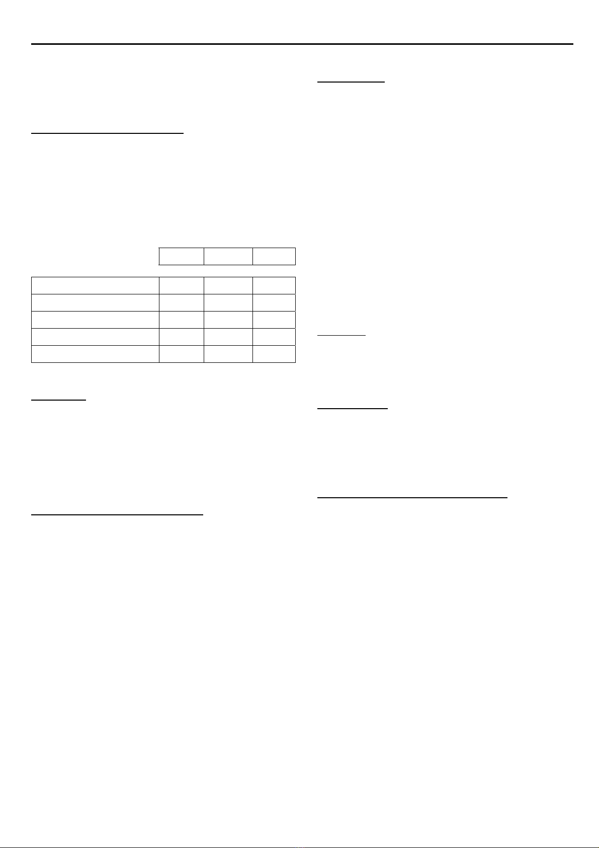
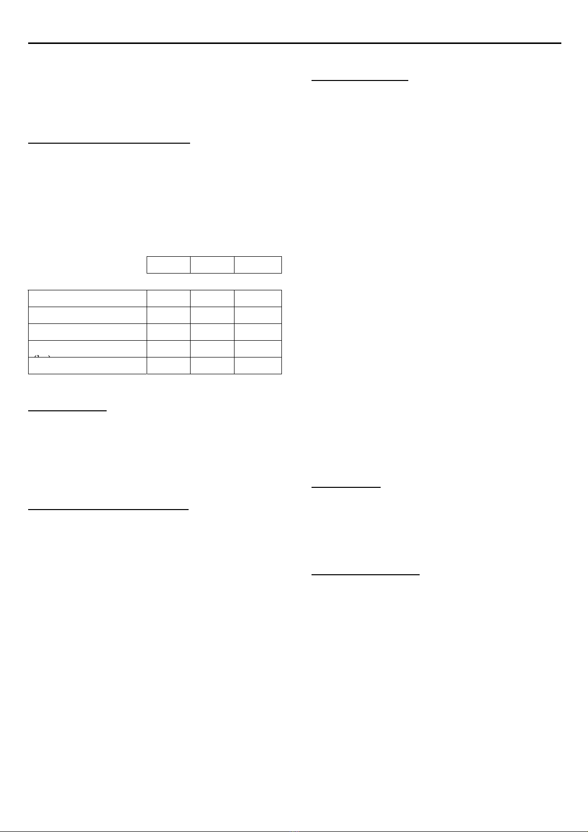
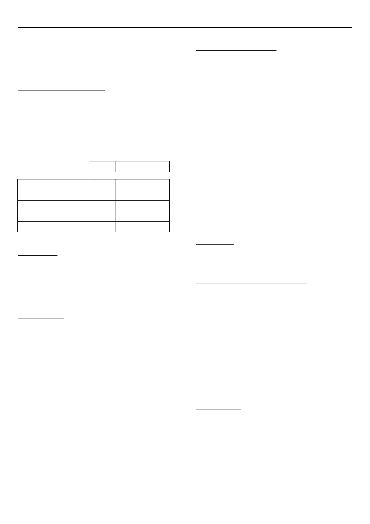
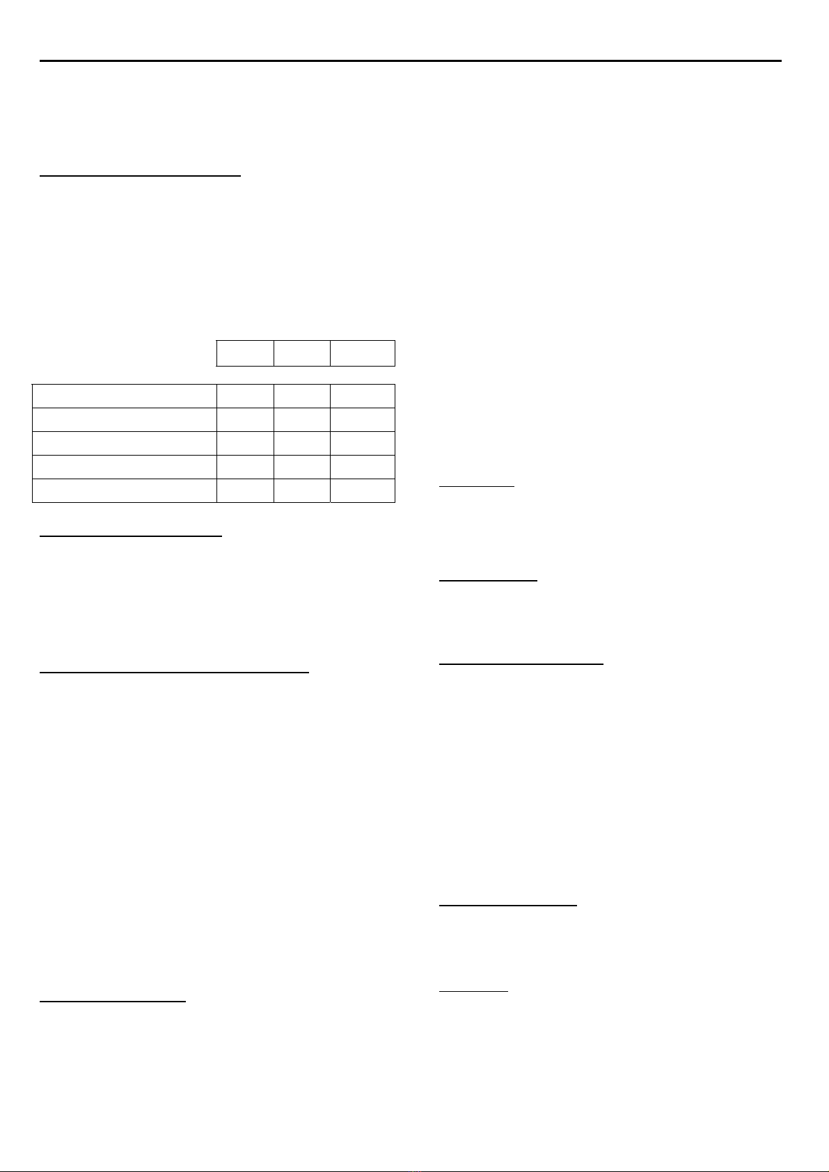
TECHNISCHE DATEN
Maximaler Systemdruck 2 bar
Maximale Temperatur 35°C
Spannung 230 V
Drehzahl bei 50 Hz 2800 min-1
Schutzart IP 44
Isolationsklasse F
Schallpegel der Filtrieranlage > 70 dB (A)
∅375 ∅475 ∅560
Filterfläche (m2) 0.11 0.18 0.25
Filterleistung (m3/h) 5 9 12
Kies ∅3-5 mm (kg) 12 15 20
Sand ∅0.35-0.5mm (kg) 30 65 120
Leergewicht Filter (kg) 15 18 24
ALLGEMEIN
Überprüfen Sie den Karton auf Anzeichen von Schäden,
die auf eine unsachgemäße Behandlung während des
Transports zurückzuführen sind.
Benachrichtigen Sie sofort die Transportgesellschaft,
falls irgendein Teil beschädigt ist.
Die Filtrieranlage darf nur für das Filtrieren von
Schimmbadwasser, Gartenteichwasser oder ähnliche
Anwendungen benutzt werden.
INSTALLATION-ANLEITUNGEN
Hinweis:
Es können besondere Anforderungen bestehen für
Filterinstallationen zur Verwendung an
Schwimmbecken, Gartenteiche oder ähnliche Orte.
Die Filterinstallation sollte auf einem ebenen und festen
Fundament befestigt werden, das hoch genug ist damit
der Pumpenmotor nicht durch Bodenwasser unterspült
wird.
Installieren Sie die Filterinstallation an einem
geschützten Ort und achten Sie dabei auf eine
ungehinderte Belüftung.
Bringen sie die Filtrieranlage an dem endgültigen Platz
an. Achten Sie dabei auf eine einfache Zugänglichkeit
des Ventils. Montieren Sie erst dann die Leitungen. Am
besten sollten Kunststoffleitungen benutzt werden.
Verwenden Sie Schlauchstücke mit entsprechender
Länge und entsprechendem Durchmesser und
verwenden Sie nur eine Mindestanzahl an
Winkelstücken. Verwenden Sie eine direkte und kurze
Ansaugleitung und achten Sie auf eine gleichmäßige
Neigung des Ansaugschlauchs, um somit lange
Ansaugzeiten zu vermeiden.Es ist von grundlegender
Wichtigkeit, dass die Ansaugleitung frei von jeglichen
Leckstellen ist. Der
Ansaugschlauch sollte mindestens den gleichen
Durchmesser wie der Ansaugstutzen der Pumpe
aufweisen.
BETRIEB
Vor Einschütten der Stoffe in den Filter kontrollieren Sie
das Innere und überprüfen Sie das niedrigliegenden
Verteilersystem (8 und 7) auf möglicherweise durch den
Transport verursachte gebrochene oder lose Filterdüsen.
Füllen Sie den Tank 1/3 mit Wasser.
Kontrollieren Sie, ob der Sandaufsatz (13) über dem
Rohr (6) sitzt. Füllen Sie dann den Filter zunächst mit
der angegebenen Menge Kiesel, und danach mit dem
Sand. Entfernen Sie den Sandaufzatz.
Schmieren Sie die O-ring (9 und 11) von dem Ventil
(10) mit Vaseline ein. Bringen Sie das Ventil (10) auf
dem Filter an und befestigen Sie dieses mit dem
Klemring (12).
Schließen Sie die Leitungen an. Bringen Sie das Ventil
in Position “Nachspülen” und lassen Sie die Pumpe
mindestens 1 Minute lang laufen.
Füllen Sie vor der Inbetriebnahme der Pumpe den
Vorfilter bis auf die Höhe des Ansaugstutzens mit
Wasser auf.
Schmieren Sie den Dichtungsring des Deckels bei jedem
Abnehmen des Deckels mit einer Silikonpaste ein.
Legen sie den Motor an, die Pumpe fängt an zu saugen.
Die Ansaugdauer hängt von der Ansaughöhe und der
Entfernung zu dem Schwimmbecken ab.
Dabei sind fünf Minuten eine angemessene Dauer.
Die Ansaughöhe beträgt höchstens 4 meter.
ACHTUNG: NIEMALS DIE POSITION DES
VENTILHEBELS UMSTELLEN WENN DIE PUMPE
LÄUFT. NIEMALS DAS VENTIL DEMONTIEREN WENN
DER FILTER UNTER DRUCK IST.
FILTERBETRIEB
1. Schieben Sie den Ventilhebel auf Filterstellung.
2. Setzen Sie die Pumpe in Betrieb.
3. Notieren Sie den Druck.
REINIGUNG ( Rückspülung ) DES FILTERS
Steigt der Druck ungefähr bis 0.5 Bar über den notierten
Druckwert an, ist es Zeit zur Rückspülung.
1. Stellen Sie die Pumpe ab.
2. Schieben Sie den Ventilhebel auf “Rückspülen”
3. Setzen Sie die Pumpe in Betrieb. Die Anlage soll
rückspulen bis das Wasser sauber erscheint (+/- drei
Minuten)
4. Stellen Sie die Pumpe ab
5. Stellen Sie den Ventilhebel auf “Nachspülen”
6. Setzen Sie die Pumpe in Betrieb und lassen Sie sie
ungefähr eine Minute laufen
7. Schalten Sie die Pumpe ab
8. Legen Sie den Ventilhebel wieder auf “Becken
filtern”und setzen Sie die Pumpe in Betrieb