Pentair Pool Products RO-2600 User manual

Model RO-2600
5 Stage Reverse Osmosis System With Pump
Installation and Operation Manual
145600 Rev ESE11
OPERATING SPECIFICATIONS
WARNING: Before installing the system, make certain
your water supply complies with the
following operating specications. Failure
to do so may reduce the effectiveness of the
system and will void the warranty. Consult
your local water treatment utility or a certied
water testing lab to determine the quality for
your water and use the table below to record
your results for future reference.
RO-2600 Specications
Thin Film Membrane: TLC 75
Pressure Range: 1.4–6.9 bar
Temperature Range: 4.4-37.7°C
Total Dissolved Solids 2000 ppm
Maximum Hardness†: 10 gpg (171 mg/L)
Sulde, Iron and Manganese‡: 0 ppm < 0.1 ppm
Chlorine in Water Supply: Less than 2 ppm
pH Limits: 3–11
Daily Product Water Rate*: 227 Lpd
TDS Rejection: 90% @ 2 bar inlet
Turbidity: 5 NTU Max
†If the hardness of your water is above 10 gpg (171 mg/L), lime scale will build
up rapidly on the membrane inside of the RO membrane cartridge. Scale
buildup will plug the RO membrane cartridge and make the system ineffective.
We do not recommend the reverse osmosis system to be used with water in
excess of 10 gpg (171 mg/L) hardness.
‡A maximum total level of approximately 0.01 ppm sulde, iron or manganese is
permissible. See your local dealer to reduce these substances in your water.
*Based on manufacturer's internal testing.
RO-2600 Dimensions:
Overall Dimensions 45.7 x 20.3 x 45.7 cm
Tank Dimensions 34.3 x 27.9 cm
Weight 10.4 kg
Tank Capacity Max. 16.5 L
Tank Air Pressure Empty 0.34 to 0.48 bar
Tank Weight Full 12.9 kg
Tools Required
• Hand or electric drill • Slotted and phillips
screwdrivers
• 2 Adjustable wrenches • Drill bits: 1/8", 1/4" and 3/8"
• File • Safety glasses
Optional Materials
(For sinks without extra hole for faucet)
• Center punch • 1⅜ inch hole saw or drill bit
• Cone-shaped grinding
wheel
• Safety mask
NOTE: All tools listed will not be necessary for installation.
Read installation procedures before starting to
determine required tools.
Parts Included (See back of manual for diagram)
• Pre-assembled lter system (mounting bracket, membrane
housing, prelter housings, pre- and postlter cartridges,
booster pump, transformer, high and low pressure
switches, solenoid valve).
• RO membrane • Installation Kit
• Storage Tank

GENERAL PRECAUTIONS
WARNING:
Do not use with water that is
microbiologically unsafe or of unknown
quality without adequate disinfection before
or after the system.
CAUTION Filter must be protected against freezing which
can cause cracking of the lter and water
leakage.
CAUTION
Because of the product’s limited service life
and to prevent costly repairs or possible
water damage, we strongly recommend that
the bottom of all plastic housings be replaced
every ve years for clear and ten years for
opaque. If the bottom of your housing has been
in use for longer than this period, it should be
replaced immediately. Date the bottom of any
new or replacement housing to indicate the next
recommended replacement date.
NOTE: Your water must be within required limits for
satisfactory operation. If not, your membrane life
may be shortened and your warranty will be voided
(see Operating Specications).
NOTE: This reverse osmosis system will not protect
against disease-causing bacteria or remove
naturally-occurring harmless bacteria.
NOTE: Install on cold water line only.
NOTE: Do not use wicking or sealer to t connections into
the cap of the lter. Teon® tape is recommended.
NOTE: Make certain that installation complies with all state
and local laws and regulations.
NOTE: The replacement cartridges and reverse osmosis
membrane included with this system have limited
service lives. Changes in taste, odor, and color of
the water being ltered indicate that the cartridge
should be replaced (see Replacing the Pre- and
Postlters, and Replacing the Membrane).
NOTE: After prolonged periods of non-use (such as during
a vacation) it is recommended that the system be
ushed for 5 minutes before it is used.
NOTE: A drinking water cartridge may contain carbon
nes (very ne black powder). After installation,
ush the cartridge for 5 minutes to remove the
carbon nes before using the water.
NOTE: It is recommended that you run the tap at least
20 seconds prior to using water for drinking or
cooking purposes.
NOTE: The contaminants or other substances removed
or reduced by this water treatment device are not
necessarily present in your water.
NOTE: There are no user-serviceable parts in the AC
adapter or pump. In the event of a failure these
should be replaced.
NOTE: All electrical connections must be completed
according to local codes.
NOTE: Use only the power adapter that is supplied.
NOTE: The power outlet must be grounded. A ground fault
interrupter outlet is recommended.
RO MEMBRANE PRECAUTIONS
CAUTION Chlorine will destroy the TLC 75 membrane.
If you use the RO-2600 with a chlorinated or
periodically-chlorinated water supply, it is
ABSOLUTELY NECESSARY to use a carbon
prelter (included with the system). This carbon
prelter should be changed at least every 6
months to avoid chlorine bypass. See Warranty
for disclaimers and limitations that apply to the
TLC 75 membrane.
NOTE: To make sure no chlorine is present in the water
that reaches the membrane, you may want to use a
chlorine test kit to check the brine/reject water that
ows from the membrane to the drain. No chlorine
should be detected.
NOTE: The TLC 75 membrane is resistant to naturally-
occurring bacteria.
HOW REVERSE OSMOSIS (RO) WORKS
The RO-2600 Reverse Osmosis (RO) System uses a semi-
permeable membrane to reduce dissolved salts and minerals,
improving the taste and odor of your water. The RO membrane
is made of layers of micron-thin lm wound around a hollow
center core. Water molecules can pass through the membrane,
but dissolved salts and minerals are rejected.
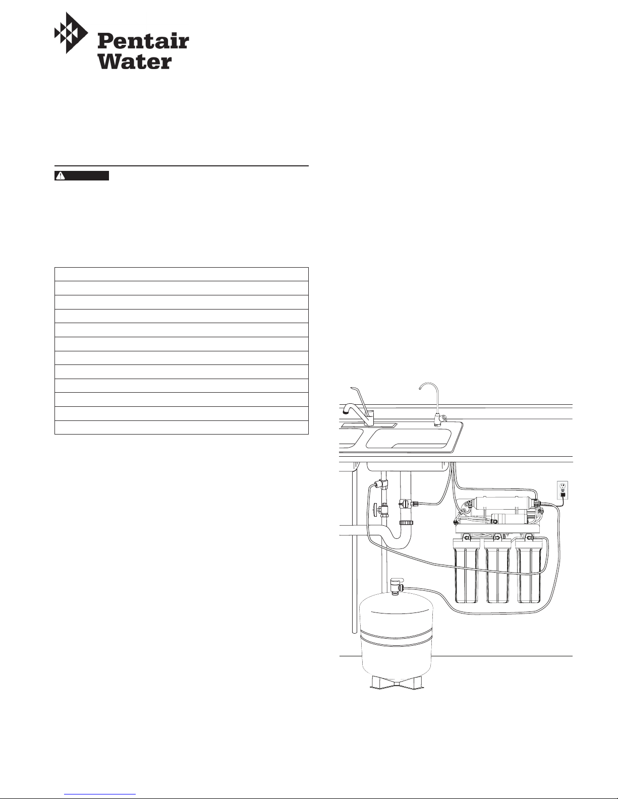
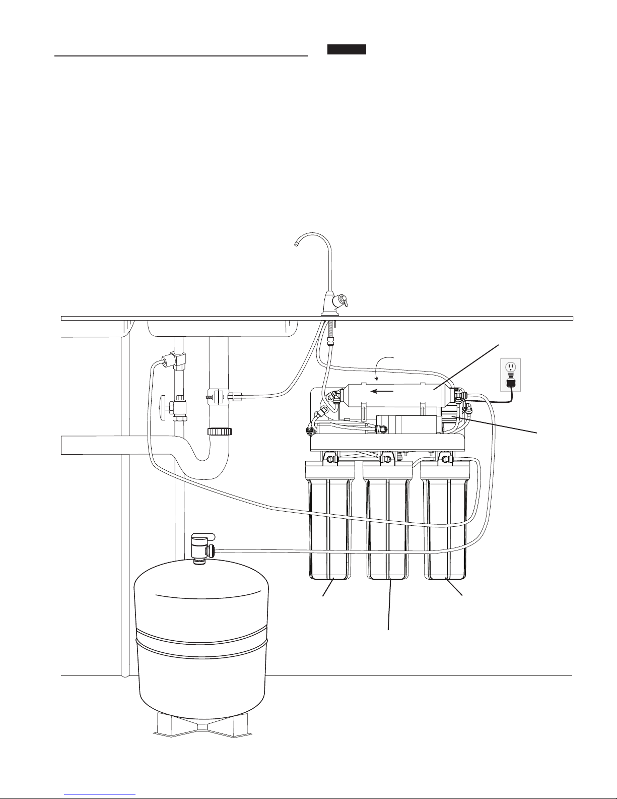
The RO-2600 Reverse Osmosis System features 5-stage
lter action. Your water supply is preltered to reduce dirt and
chlorine that may foul the membrane. The RO membrane
separates this preltered water into PRODUCT WATER and
DRAIN or REJECT WATER. Incoming water pressure forces
the product water through the membrane and into the storage
tank. Dissolved solids and other contaminants cannot pass
through the membrane and are sent to the drain as reject
water. When you open the drinking water faucet, product water
is drawn from the storage tank through an activated carbon
postlter, providing you with cleaner, great-tasting water.
For each gallon of water produced, several gallons are
discharged as reject water. The storage tank can hold up to
12.1 L of water at a time, for drinking and cooking needs.
When used under the Specications on page 1 of the manual,
your Reverse Osmosis membranes should last 12-24 months.
2 • SE11 Model RO-2600 5 StageReverse Osmosis System

INSTALLATION
NOTE: Please read all instructions, specications, and
precautions before installing and using your
RO-2600.
NOTE: For standard, under-sink installation on 3/8-inch
(10 mm) steel, brass, or copper cold water line.
NOTE: Lettered diagrams correspond with lettered steps.
1. Installing the Water Supply Adapter
The supply adapter ts 1/2" 14 NPS supply threads. If local
codes permit, it may be used to connect the lter system
to the cold water supply line. If local codes do not permit
the use of the supply adapter, alternate connectors can be
obtained from your local plumbing wholesaler.
A. Turn off cold water supply line. If cold water line does
not have a shut-off valve under the sink, one should be
installed.
B. Turn on the cold water faucet and allow all water to
drain from line.
C. Disconnect cold water line from 1/2" 14 NPS threaded
stub on bottom of main faucet.
D. Screw the water supply adapter to the threaded faucet
stub as shown.
E. Using the nut that previously connected the cold water
line to the faucet, screw the cold water line to the male
supply adapter threads.
D
A
B
C
D
E
Figure 1
2. Selecting the Faucet Location
NOTE: The drinking water faucet should be positioned
with function, convenience, and appearance in
mind. An adequate at area is required to allow
faucet base to rest securely. The faucet ts through
a 1⅜" hole. Most sinks have pre-drilled 1⅜" or
1½" diameter holes that may be used for faucet
installation. If these pre-drilled holes cannot be
used or are in an inconvenient location, it will
be necessary to drill a 1⅜" hole in the sink to
accommodate the faucet.
WARNING:
This procedure may generate dust which
can cause severe irritation if inhaled or come
in contact with the eyes. The use of safety
glasses and respirator for this procedure is
recommended.
WARNING:
Do not attempt to drill through an all-
porcelain sink. If you have an all-porcelain
sink, mount the faucet in pre-drilled sprayer
hole or drill through countertop next to sink.
WARNING:
When drilling through a countertop, make
sure the area below the drilled area is free of
wiring and piping. Make certain that you have
ample room to make the proper connections
to the bottom of the faucet.
WARNING:
Do not drill through a countertop that is more
than 1" thick.
WARNING: Do not attempt to drill through a tiled, marble,
granite or similar countertop. Consult a
plumber or the countertop manufacturer for
advice or assistance.
A. Line bottom of sink with newspaper to prevent metal
shavings, parts, or tools from falling down drain.
B. Place masking tape over the area to be drilled to help
prevent scratches if drill bit slips.
C. Mark hole with center punch. Use a 1/4" drill bit for a
pilot hole.
D. Using a 1⅜" hole saw, drill a hole completely through
the sink. Smooth the rough edges with a le.
D
C
1⁄4”
11⁄4”
A
B
C
D
Figure 2
Model RO-2600 5 StageReverse Osmosis System SE11 • 3

3. Mounting the Faucet
A. Pre-assemble the base. The rubber washer should be
in place below the base. The two toggle bolts should be
inserted through the base and the rubber washer. The
bolts are screwed into the spring-loaded toggle.
B. Place the base assembly over the hole in the sink. The
two toggles should pass through the hole far enough to
spring fully open. If they are not open, unscrew the bolt
until the toggle moves down to clear the sink.
C. Look down through the base for this step. Before
tightening the bolts, determine the correct rotation of the
base. The nal position of the handle will be 45 degrees
off from the bolt heads. Use Figure 5 to help determine
the best position for your installation.
Through the hole in the base, hold the toggle in position
while tightening the bolt. The spring loaded toggle
will contact the bottom of the counter top and hold in
position. Do not fully tighten. Repeat for second toggle
bolt.
Check the nal position of the base and toggle bolts.
Tighten the two bolts evenly. DO NOT OVERTIGHTEN.
Tighten only far enough to prevent the base from
rotating when the faucet is rotated in place.
D. Check that the O-ring is in place on the faucet. Feed
the three tubes throught the base. Hold the faucet in
the nal position and rotate backwards (to the left) while
pushing down. The faucet will drop into the base. Push
down on the faucet and rotate forward (to the right) to
lock it into nal position. The O-ring will be seated and
the faucet held securely in position.
E. Apply silicone lubricant to the O-rings on the faucet
spout and insert the spout into the top opening. Hold in
position and screw the collar onto the base.
NOTE: If the faucet handle is not in the correct position,
remove the faucet, loosen the toggle bolts and
reposition the base. Tighten the toggle bolts. Then
reinstall the faucet.
Base
Black Rubber
Washer
Folds Upward
A
Figure 3
BBase
Will Spring Open
O-ring Seat
Figure 4
C
Handle Faces This Direction
45°
Notch For Faucet
Blades Must Be Held
When Tightening
Notch For Faucet
Figure 5
D
E
O-Ring
Figure 6
4. Installing the Drain Clamp
NOTE: If you have a single-basin sink with a disposal unit,
call Technical Support for options.
NOTE: Before installing the drain clamp, check the
drainpipes under the sink for corrosion. Corroded
pipes should be replaced before continuing with
installation.
A. Attach the drain clamp to a vertical section of the
drainpipe, about 6 inches above the trap. Make sure
the opening on the drain clamp is facing towards the
drinking water faucet (see Figure 12).
6"
A
Figure 7
INSTALLATION continued
4 • SE11 Model RO-2600 5 StageReverse Osmosis System

B. Using the tting hole of the drain clamp as a guide, drill
a 1/4-inch hole through one side of the drainpipe.
C. Remove the drain clamp from the drainpipe and enlarge
the hole with a 3/8-inch drill bit. Use a le to remove
rough edges from the drilled hole.
BC
Figure 8
D. Make sure the black rubber gasket is adhered to the
inside of the drain clamp and place the drain clamp
assembly over the drilled hole. Look through the hole
and position the clamp so that the center of the clamp
hole is slightly higher (about 1/16-inch) than the center
of the drilled hole. Tighten the clamp securely.
E. Screw the plastic compression nut onto the drain clamp
until hand-tight.
D
E
Figure 9
5. Connecting the Faucet to the Drain
CAUTION
This is a gravity drain line. Any loops, kinks
or sharp bends must be eliminated before
proceeding. Failure to create a straight line
to the drain may result in reject water leaking
through the air gap in the faucet onto the
countertop and below the faucet.
A. Align the larger reject (3/8-inch) tubing from the faucet
with the compression nut on the drain clamp. Create as
straight and smooth a path as possible with the tubing.
Do not kink tube. Cut the tubing squarely below the nut
and remove the internal and external burrs.
INSTALLATION continued
B. Loosen the compression nut two complete turns. Insert
the tubing into the nut until it stops. Tighten with ngers,
then tighten 1 to 2 turns with a wrench.
B
A3/8" Tube
Figure 10
6. Installation of Mounting Screws
A. If system is being installed under the kitchen sink,
locate it on the back or right side wall. Make sure to
allow ample space for installation. To change the lter
cartridges, a minimum of 1½ inches of clearance is
required underneath the lter housings. A minimum of 2
inches of clearance from the left side of the unit is also
required.
B. Install mounting screws at least 15 inches from cabinet
oor and 9-inches apart. Leave a 5/16-inch space
between the head of the screw and the wall to slip
bracket onto screws.
NOTE: Each connection tting on the RO Assembly has a
plug that must be removed before inserting tubing.
Push in on the collar and pull the plug out.
9"
15"
1½"
Figure 11
Model RO-2600 5 StageReverse Osmosis System SE11 • 5

INSTALLATION continued
Figure 12
3/8" Drain
Tube
1/4" Faucet
Permeate Tube
7. Connecting the Faucet to the System
A. Locate the reject tubing (reject water line) from the
drinking water faucet. This tube is the smaller of the
two. Place a mark on the tubing 5/8-inch from the end.
Moisten the end of the tubing with water and insert
tubing into the quick-connect tting on the ow restrictor
found on the right side of system behind the membrane.
If tubing is not rmly connected, leaking will occur. It
is important for the tubing to be inserted all the way
until the mark is ush with the outer edge of the quick-
connect insert.
NOTE: Tubing may be quickly and easily removed from
the tting if necessary by pressing the collar
around the tting then pulling the tubing with
your other hand.
B. The faucet tube from the bottom of the threaded metal
tube is inserted into the post lter. The tting is at the
top left of the RO System. Push the free end of the
tubing into the quick connect tting.
1/4" Feed
Tube
3rd Stage
Carbon Block
2nd Stage
GAC Filter
1st Stage
Prelter
1/4" Storage Tank
Permeate Tube
1/4" Faucet
Drain Tube
6 • SE11 Model RO-2600 5 StageReverse Osmosis System

8. Connecting the Storage Tank to the System
CAUTION
When tank is full, it weighs approximately
29 kg. Provide ample support under the tank.
A. To prevent leaks, apply 3 or more wraps of Teon tape
to threads on tank. Thread the tank valve onto the top
of the tank opening. Turn tank so handle is in line with
tubing.
CAUTION
The tank/valve connection will leak if not
properly sealed. Teon tape will normally seal
the threaded connection.
B. Locate the 1/4-inch tubing. Place a mark on the tubing
5/8-inch from each end. Moisten one end of the tubing
with water and insert with a twisting motion into the port
of the tank valve until the 5/8-inch mark is ush with
the quick connect tting. Then locate the tank near the
system's installation area.
1/4" Tube
Apply
Teon
tape
5/8"
A
B
Figure 13
C. Cut the tubing to correct length. Install free end of tubing
into white quick-connect tting on the post lter tee on
the right side. Do not cut tubing again.
D. Place entire system over mounting screws on wall and
slide down.
CAUTION
Make certain system is rmly attached to wall
to prevent it from falling and possibly becoming
damaged.
NOTE: Use caution not to bend or pinch the tubing behind
the system while attaching to mounting screws.
9. Connecting the Supply Adapter and Inlet Filter
A. Locate remaining length of 1/4-inch plastic tubing.
B. Push into quick connect tting on the right side of
system.
C. Cut the tube to a length that will allow connection to the
cold water supply tting. Ensure the tubing does not
kink. Push the tube into the tting.
1/4" Tube
5/8"
16 mm
C
A5/8"
16 mm
Figure 14
INSTALLATION continued
10. Installing the Membrane
A. Remove tube attached to membrane housing by
pressing in the white collar around the tting while
pulling the tubing with your other hand.
B. Hold the membrane housing with one hand and
unscrew the cap (wrench provided) with other hand
to remove. To make it easier to hold the membrane
housing, you may want to remove the postlter.
C. With clean hands (sanitary gloves preferred), remove
the membrane from the plastic bag. HANDLE WITH
CARE.
CAUTION
Do not unwrap the tape around the membrane,
as it is part of the membrane. Do not squeeze
membrane.
D. With the double O-ring side rst, push membrane into
housing until it stops.
About 1/8-inch of the membrane’s plastic core will stick
out beyond the housing.
D
A
Figure 15
E. Use clean silicone grease (pack is included with the
system) to lubricate both O-rings and the brine seal.
Hand-tighten membrane housing cap until you feel
resistance, then tighten an additional 1/2 turn. Do not
over-tighten.
F. Reinsert the tube by pushing it into the quick connect
tting.
11. Faucet Operation
For controlled water ow, rotate the handle to the right
(clockwise).
Model RO-2600 5 StageReverse Osmosis System SE11 • 7

12. System Start-up
NOTE: The reverse osmosis membrane is treated with
a food grade sanitizing agent that may cause an
undesirable taste. Although it is not harmful, it
should be ushed from the system.
NOTE: The GAC and post-polishing lter may contain ne
black carbon particles. These nes are harmless,
but may make the water appear gray in color. The
carbon nes are ushed from the system with the
rst tank full of water.
NOTE: The RO system does not produce a high volume
of water on demand as an ordinary lter does.
Water is produced at a slow, drop-by-drop rate.
The system requires about 2 to 4 hours to ll the
storage tank. As water is taken from the tank, the
system automatically starts the cycle of replacing
the water and then stops water production when
the tank is full.
CAUTION
Visually check the entire system for leaks. If a
leak is present, see Troubleshooting.
CAUTION
This unit is for dry location use only.
A. Plug unit into a live grounded electrical socket.
B. Turn off valve at top of storage tank.
C
Closed
Tank Valve
Counter-
clockwise
Open
Tank Valve
B
Figure 16
C. Completely open the cold water supply.
D. Rotate the faucet handle to the open position.
E. Completely open the cold water supply until it comes
to a stop. Allow water to drip from the faucet for 3 more
hours. Then close the faucet and open the valve on the
storage tank. The tank valve is open when the handle
lines up with the tubing connection.
F. Allow 2 to 4 hours for the tank to ll. Continue to,
periodically check the installation for leaks. After the
storage tank is lled, open the faucet to ush the post-
polishing lter. Allow 4 to 5 minutes for all of the water to
drain from
the tank.
G. Close faucet and allow tank to ll.
H. Repeat steps E and F four times.
NOTE: Initially, the water may appear cloudy. This is a
result of air trapped in the post-polishing lter.
It is not harmful and will disappear in a matter of
minutes. It may take up to a week after installing
a new post-polishing lter for the trapped air to
dissipate.
The system is ready for operation. You can now enjoy quality
water from your Reverse Osmosis System.
INSTALLATION continued WHEN TO CHANGE THE CARTRIDGES
The life of the cartridge depends on the water volume used and
the substances in the water. Normally, cartridges should be
changed at intervals of 6 months. Replace the cartridge sooner
if the water pressure at the faucet begins to drop noticeably or
if you notice changes in the taste, color, or ow of the ltered
water.
REPLACING THE PREFILTER AND
POSTFILTER CARTRIDGES
1st, 2nd and 3rd Stage Prelter Cartridges
The cartridges should be replaced every six months. If your
water contains a high amount of sediment, it may be necessary
to change the 1st stage cartridge more frequently. If your water
contains a high amount of chlorine, it may be necessary to
change the 2nd and 3rd stage prelters more often.
1. Turn off incoming water supply and the valve on the storage
tank. Place a tray under the system to catch any water that
spills during removal of the lter housings.
2. Open faucet to release pressure.
3. Remove electrical plug from outlet.
4. Unscrew bottom of lter housings from caps. Use the lter
wrench. Discard used cartridges.
5. Remove black rubber O-rings from grooves in housings.
Wipe grooves and O-rings clean; set O-rings aside.
6. Rinse out housings and ll each 1/3 with water. Add 2
tablespoons of bleach and scrub with non-abrasive brush
or sponge. Rinse thoroughly.
7. Lubricate each O-ring with a coating of clean silicone
grease. With two ngers, press each O-ring securely into
groove below the threads of the appropriate housing.
CAUTION The rubber O-ring provides the water-tight seal
between the cap and the bottom of the housing.
It is important that the O-ring be properly seated
in the groove below the threads of the housing
or a water leak could occur.
Figure 17
8. Insert cartridges in the bottom of the housings. Make sure
cartridge slips over standpipe in the bottom of the housing.
NOTE: Be sure to install cartridges in proper housings
(see diagram below).
9. Screw bottoms of housings back onto caps securely; do not
over-tighten. Turn on cold water supply and open tank
valve.
10. Plug system into outlet. Check for leaks. Continue to check
periodically to make sure no leaks develop.
8 • SE11 Model RO-2600 5 StageReverse Osmosis System

5th Stage Postlter Cartridge
Postlter should be replaced every twelve months.
1. Turn off incoming water supply and valve on the storage
tank. Place a tray under the system to catch any water that
spills during removal of the lter housings.
2. Open faucet to release pressure.
3. Remove electrical plug from outlet.
4. Remove tubes from ttings by pressing in collar around the
tting while pulling the tubing out with your other hand.
5. Remove lter from bracket and discard.
NOTE: If quick connect ttings need to be installed,
tape threads of ttings with 3 wraps of Teon®
tape and attach to lter.
CAUTION
Ensure the tape is not touching O-ring on the
tting or a leak may occur.
NOTE: The lter has an arrow on it showing the
direction of ow. The tee tting connects to
the inlet side of the lter and the elbow tting
attaches to the outlet side.
NOTE: Hand tighten ttings, then tighten with wrench
1/4 turn.
6. Attach 5th stage lter to bracket with the tee tting on the
right hand side.
7. Attach tubes to ttings by pushing in until the tube stops.
Check to see if tube is in place by trying to gently pull tube
out.
8. See Step 12: System Start-up.
REPLACING THE PREFILTER AND
POSTFILTER CARTRIDGES continued
Figure 18
Flow Restrictor
5th Stage Activated Carbon Postlter
4th Stage RO
Membrane
Flow
1st Stage Prelter
2nd Stage GAC Filter
3rd Stage Carbon Block
Model RO-2600 5 StageReverse Osmosis System SE11 • 9

REPLACING THE 4TH STAGE REVERSE
OSMOSIS MEMBRANE
About the Reverse Osmosis Membrane
When used under operating conditions specied on page 1
of the manual, your reverse osmosis membrane should last
at least one year. You should replace the membrane after
18 to 24 months. Replace it sooner if you notice a return of
unpleasant tastes or odors or a noticeable decline in water
production. The precise life span of your system's membrane
will depend on the quality of the water entering the system
and the frequency with which you use it. Frequent system use
prevents the ltered salts and minerals from building up on the
membrane as scale. The more water the system is required to
produce, the longer the membrane will last. You may wish to
nd a variety of uses for your system in order to prolong the life
of the membrane.
During extended periods of non-use (such as during a
vacation), remove the membrane from the membrane housing
and place it in a sealed plastic bag. Store membrane in
refrigerator for future use. DO NOT FREEZE.
NOTE: If system stands for more than 2 to 3 days without
being used, the storage tank should be emptied.
Replacing the Membrane and Sanitizing the
System and Filters
NOTE: It is recommended that you sanitize the system
each time you change the membrane. It is not
necessary to sanitize the system when changing
only the prelters or postlter.
NOTE: When installing a new membrane, it is
recommended that you replace the prelter and
postlter cartridges as well.
Removing the Membrane and Filters
1. Turn off the cold water supply. Allow ve minutes for system
to depressurize.
Place a tray under the system to catch any water that spills
during removal of the lter housings.
2. Remove electrical plug from outlet.
3. Open drinking water faucet to drain tank. When tank is
drained, close faucet.
4. Hold the membrane housing with one hand and remove the
cap with the other hand.
CAUTION Do not disconnect tubing from membrane cap.
5. To remove the RO membrane, grasp membrane tube with
pliers and pull. Discard old membrane. Screw cap back
onto membrane housing. DO NOT install new membrane.
6. Unscrew lter housings from caps and discard used
cartridges.
7. Remove black rubber O-rings from grooves in housings.
Wipe grooves and O-rings clean; set O-rings aside.
Sanitizing the System
1. Rinse out bottom of housings and ll each 1/3 with water.
Add 2 tablespoons of household bleach to each housing
and scrub cap, bottom of housings, and membrane housing
with non-abrasive sponge or cloth. Rinse thoroughly.
2. Lubricate O-rings with a coating of clean silicone grease.
With two ngers, press each O-ring securely into groove
below the threads of the appropriate housing.
CAUTION The rubber O-ring provides the water-tight seal
between the cap and the bottom of the housing.
It is important that the O-ring be properly seated
in the groove below the threads of the housing
or a water leak could occur.
3. Screw bottom of housing onto caps WITHOUT inserting
prelters and hand-tighten. Do not over-tighten.
4. Open the cold water supply and let the system run for 2 to 3
minutes to carry the bleach solution throughout the system.
5. Close the cold water supply and turn on the drinking water
faucet. Let the faucet run for about 30 seconds before
turning off.
6. Let the entire system stand for 30 minutes to sanitize.
7. After 30 minutes, turn on the drinking water faucet to allow
the bleach water to run out (about 3 to 5 minutes).
8. Unscrew bottom of housings. Discard bleach water and
rinse.
Replacing the Membrane and Filter Cartridges
To replace the lters, see Replacing the Prelters and
Postlter.
To replace the membrane, see Step 10: Installing the
Membrane, and Step 12: System Start-up.
NOTE: After installing new membrane and cartridges,
allow system to run for 3 hours to ll tank. Check
for leaks every hour. As pressure builds in tank,
leaks may occur that did not exist directly after
installation.
10 • SE11 Model RO-2600 5 StageReverse Osmosis System

TROUBLESHOOTING
Leaks between bottom of housing and cap
1. Ensure sump is tightly screwed to cap. If it still leaks close
the cold water supply and tank valves.
2. Remove housing and clean the black rubber O-ring.
Lubricate with clean silicone grease. With two ngers, insert
O-ring in groove below threads of housing and press into
place. Tighten housing back onto cap.
3. Open the cold water supply and tank valve. If leaks persist,
call Technical Support.
Leaks on tank valve assembly
1. Open drinking water faucet to drain storage tank. Let
drinking water faucet run until it drips. Turn off cold water
supply.
2. Push in on white collar of tank valve tting and pull out
tubing. Unscrew the tank valve from the storage tank.
Rewrap threads on top of the tank with Teon® tape. Screw
tank valve back onto tank. Trim 1/2-inch from end of tubing
and reinsert 5/8-inch into tank valve tting.
3. Open the cold water supply and shut off the reverse
osmosis faucet. Let the system pressurize for several
hours and check for leaks. Check again after tank is fully
pressurized.
Leaks on quick-connect ttings
1. Close the cold water supply and tank valve.
2. Depress plastic collar and pull out tubing.
3. Cut off 1 inch of tubing and place a mark 5/8-inch from end
of tubing. Tubing should be cut squarely. The internal and
external burrs should be removed.
4. Push tubing 5/8-inch into tting.
5. Open the cold water supply and tank valve. If leaks persist,
call Technical Support.
No ow or slow ow from the brine (drain) line
Less than 1½ cups per minute
NOTE: Before checking brine (or reject) ow, make sure
the system is producing water by turning off the
valve on the storage tank and opening the faucet.
Water should drip from faucet.
1. Examine the prelters. If clogged, replace (see Replacing
the Prelter and Postlter Cartridges) and recheck the brine
(or reject) ow rate.
2. If the prelters are not at fault, the brine (or drain) ow
controller is probably clogged. Call Technical Support.
High TDS in Product Water
If high levels of TDS (Total Dissolved Solids) are detected in
your product water (approximately 30% or greater of what is
measured in your tap water, as determined with a conductivity
meter or by a TDS Test Kit), the RO membrane may need to
be replaced, or the brine (or drain) ow control tubing may be
clogged. See your dealer or plumber to check product water
TDS.
Reduced production
Slow or no product water ow usually indicates either a
clogged prelter or an exhausted membrane. First, replace
the prelters. If the production rate is not improved, replace
membrane.
Gradual return of taste and odor
Gradual return of unpleasant taste and odor over a period
of time may indicate that your lter cartridges and/or RO
membrane need to be replaced. See Replacing the Prelters
and Replacing the Reverse Osmosis Membrane.
Sudden return of taste and odor
If shortly after complete servicing noticeable taste and odors
return contact Technical Support.
No water pressure from the drinking water
faucet or low volume in storage tank
1. Close the cold water supply to system.
2. Lift storage tank to see if it is empty. If not, open the
drinking water faucet to empty water from tank.
NOTE: It may be necessary to pump a small amount of air
into the tank with a bicycle pump to remove all the
water from the tank.
3. When tank is empty, use a pressure gauge to check
tank pressure. An empty tank should contain 5 to 7 psi
pressure. Increase or decrease the air pressure in the tank
accordingly.
4. Open cold water supply. Let system run for
3 hours to ll tank, then check system performance. If
performance has not improved, call Technical Support.
Model RO-2600 5 StageReverse Osmosis System SE11 • 11

REPLACEMENT PARTS
For replacement parts contact your local retailer or call
Customer Service.
Item
#
Part Number Description QTY
1 155014-43 Sediment Filter 1
2 155109-43 GAC Cartridge 1
3 155634-43 EPM-10 Cartridge 1
4 555693-00 TLC 75 Element 1
5 255720-06 Inline Cartridge GS-10RO-B 1
6 153049 Housing 1
7 8015-014-011 Booster Pump 1
860-044-01 Transformer - Dual Voltage 1
9SARO-50-13 High Pressure Switch 1
10 SA10007-434400002 Low Pressure Switch 1
11 SAMC-60-B2-15 Solenoid valve 1
12 161080 Membrane Housing 1
13 150539 Sump Wrench 1
14 150640 RO Housing Wrench 1
15 SH244857 Chrome Faucet 1
16 SH244877 Storage Tank 1
17 SH244783 Tank Valve 1
18 SH244796 Drain Clamp 1
19 SH244797 Inlet Supply Adapter 1
20 SH244837 Flow Restrictor 1
1
8
6
5432
11
12
13 14
15
16
17
18
19
20
10
9
7
©2011 Pentair Residential Filtration, LLC

Modèle RO-2600
Système d'osmose inverse cinq étapes avec pompe
Manuel d'installation et d’utilisation
CARACTÉRISTIQUES DE
FONCTIONNEMENT
AVERTISSEMENT : Avant de procéder à l'installation du
système, assurez-vous de la conformité
de votre alimentation en eau avec les
caractéristiques de fonctionnement
suivantes. Ne pas le faire entraînera une
diminution de l'efcacité du système et
l'annulation de la garantie. Consultez la
société locale de traitement des eaux ou
un laboratoire agréé d'analyse des eaux
pour déterminer la qualité de votre eau
et servez-vous du tableau ci-après pour
enregistrer les résultats obtenus aux ns
de consultation ultérieure.
Caractéristiques du RO-2600
Membrane à lm ultramince : TLC 75
Plage de pression : 1,4 à 6,9 bars
Plage de température : 4,4 à 37,7°C
Concentration totale en matières
dissoutes
2000 ppm
Dureté maximale † : 171 mg/l
Sulfures, fer et manganèse‡ : 0 ppm < 0,1 ppm
Chlore dans l'alimentation en eau : Moins de 2 ppm
Limites du pH : 3–11
Capacité de production
quotidienne d'eau* :
227 l/j
Rejet TDS : 90 % pour une pression
de 2 bars à l'entrée
Turbidité : 5 NTU max.
†Si la dureté de votre eau est supérieure à 171 mg/l, des dépôts de tartre se
formeront rapidement sur la membrane présente à l'intérieur du carter à
membrane. Ces dépôts de tartre niront par obturer la membrane,
et rendre le système inopérant. Nous déconseillons d'utiliser
le système d'osmose inverse avec une eau dont la dureté est
supérieure à 171 mg/l.
‡Le système tolère une teneur totale en sulfures, fer ou manganèse de l'ordre de
0,01 ppm. Pour réduire la teneur en sulfures, fer ou manganèse de votre eau,
consultez votre fournisseur local.
*Sur la base d’essais effectués en interne par le fabricant
Dimensions du RO-2600 :
Dimensions totales 45.7 x 20.3 x 45.7 cm
Dimensions du réservoir 34.3 x 27.9 cm
Poids 10.4 kg
Capacité max. du réservoir 16.5 L
Pression d'air du réservoir vide 0,34 à 0,48 bars
Poids du réservoir plein 12.9 kg
Outils nécessaires
• Chignole ou perceuse
électrique
• Tournevis phillips et pour vis
à tête fendue
• 2 Clés à molette • Forets : 1/8", 1/4" et 3/8"
• Lime • Lunettes de protection
Outillage optionnel
(pour éviers dépourvus d'orice de montage pour robinet)
• Pointeau de centrage • Scie cloche ou foret ⅜''
• Meule conique • Masque de protection
REMARQUE : Les outils répertoriés ne sont pas tous
indispensables à l'installation. Prenez
connaissance des procédures d'installation
avant de déterminer les outils indispensables.
Composants inclus (voir schéma au dos du manuel)
• Système de ltration préassemblé (support de montage, carter
de la membrane, carters de préltre, préltres et postfiltre,
pompe, transformateur, contacteurs haute et basse pression,
électrovanne).
• Membrane • Kit d'installation
• Réservoir de stockage

PRÉCAUTIONS GÉNÉRALES
AVERTISSEMENT : Ne pas utiliser avec une eau incertaine
sur le plan microbiologique ou d'une
qualité inconnue sans désinfection
adéquate en amont ou en aval du
système.
DANGER Le ltre doit être protégé contre le gel, lequel peut
causer une ssuration du ltre et des fuites d'eau.
DANGER En raison de la durée de vie limitée du produit
et pour prévenir toute réparation coûteuse ou
tout dégât éventuel causé par l'eau, nous vous
recommandons vivement de remplacer
OHVFDUWHUVen plastique tous les cinq ans sLOV
sont transparents et tous les dix ans sLOV
sont opaques. En cas d'utilisation dXQGHV FDUWHUV
pendant plus de dix ans, remplacez-lH
immédiatement. Inscrivez la date sur lHFDUWHU
neuf ou de rechange an d’indiquer la SURFKDLQH
date de remplacement recommandée.
REMARQUE : Votre eau doit se situer dans la plage
de tolérance requise pour garantir un
fonctionnement satisfaisant. Si ce n'est pas le
cas, la durée de vie de la membrane risque de
s'en trouver raccourcie et la garantie dont vous
bénéciez sera annulée (voir Caractéristiques
de fonctionnement).
REMARQUE : Le système dosmose inverse QDVVXUH
aucune protection contre les bactéries
pathogènes et n'élimine aucunement les
bactéries inoffensives présentes dans la nature.
REMARQUE : Installer exclusivement sur une canalisation
d'eau froide.
REMARQUE : N'utilisez ni chanvre ni pâte de scellement
pour monter les raccords sur le couvercle
du ltre. L'emploi d'un ruban de Téon®est
recommandé.
REMARQUE : Veillez à ce que l’installation satisfasse
à la législation et à toutes les lois et
réglementations nationales et locales.
REMARQUE : La durée de vie des cartouches de
rechange et de la membrane d'osmose inverse
livrées avec ce système est limitée. Toute
modication du goût, de l'odeur et de la
teinte de l'eau ltrée indique que la cartouche
doit être remplacée (voir Remplacement des
préltres et postltres et Remplacement de la
membrane).
REMARQUE : Au terme de périodes prolongées d'inutilisation
(comme par exemple pendant les vacances), il
est recommandé de rincer le système à grande
eau pendant 5 minutes avant de l'utiliser.
REMARQUE : Une cartouche ltrante peut contenir
des particules de cKDUERQ (poudre noire
extrêmement ne). Après installation, rincez la
cartouche à grande eau pendant cinq minutes
avant d'utiliser l'eau produite.
REMARQUE :Il est recommandé de laisser couler le robinet
pendant 20 secondes au moins avant d'en
prélever l’eau pour la boire ou cuisiner.
REMARQUE : Les polluants ou autres substances éliminés
ou réduits par cet équipement de traitement
des eaux ne sont pas nécessairement présents
dans votre eau.
REMARQUE : Ni lHWUDQVIRUPDWHXU ni la pompe ne comportent
de pièces réparables ou remplaçables. En cas
de panne, ces SLqFHs doivent être remplacéHs.
REMARQUE : Les connexions électriques doivent être
conformes à la réglementation locale en la
matière.
REMARQUE : Servez-vous exclusivement dXWUDQVIRUPDWHXU
livré.
REMARQUE : La prise d'alimentation secteur doit être mise
à la terre. L'emploi d'une prise assortie d'un
disjoncteur de fuite à la terre est recommandé.
PRÉCAUTIONS RELATIVES À LA
MEMBRANE '26026(,19(56(
DANGER Le chlore détruira la membrane TLC 75. Si
vous raccordez votre système RO-2600 à une
alimentation en eau chlorée en permanence ou
périodiquement, l'installation d'un préltre au
charbon actif est ABSOLUMENT INDISPENSABLE
(livré avec le système). Il convient de remplacer
ce préltre tous les six mois au moins pour éviter
toute contamination au chlore. Reportez-vous à la
garantie pour prendre connaissance des clauses
d'exonération de responsabilité et des restrictions
qui s'appliquent à la membrane TLC 75.
REMARQUE : Pour vous assurer de l'absence de chlore dans
l'eau qui atteint la membrane, servez-vous d'un
nécessaire d'analyse de la teneur en chlore
pour vérier celle de la saumure/eau rejetée
et acheminée de la membrane à la conduite
d'évacuation. Vous ne devriez détecter aucune
trace de chlore.
REMARQUE : La membrane TLC 75 est résistante aux
bactéries présentes dans la nature.
FONCTIONNEMENT DE L'OSMOSE
INVERSE
Le système d'osmose inverse RO-2600 repose
sur l'utilisation d'une membrane semi-perméable pour réduire
la teneur de l'eau en sels et en minéraux dissous, améliorant le
goût et l'odeur de votre eau. La membrane se compose de
plusieurs couches de lms ultraminces enveloppées autour d'un
noyau central creux. Les molécules d'eau peuvent traverser la
membrane, mais les sels et minéraux dissous sont rejetés.
Le système d'osmose inverse RO-2600 se caractérise
par la mise à contribution d'un dispositif de filtration en cinq étapes.
Le préltrage de votre alimentation en eau permet d'en réduire
la teneur en chlore et en particules susceptibles de souiller la
membrane. La membrane sépare cette eau préltrée en une
EAU TRAITÉE et une EAU REJETÉE. La pression de l'eau
d'alimentation contraint cette dernière à passer à travers la
membrane et à se déverser dans le réservoir de stockage. Les
sels dissous et autres contaminants ne peuvent passer à travers la
membrane. Ils sont acheminés vers la canalisation d'évacuation.
Lorsque vous ouvrez le robinet d'eau potable, l'eau puriée
prélevée dans le réservoir de stockage passe par un postltre au
charbon actif pour vous livrer une eau pure et au bon goût.
Pour chaque gallon d'eau traitée, le système évacue plusieurs
gallons d'eau rejetée. La capacité du réservoir de stockage s'élève
à 12,1 l d'eau puriée. Cette quantité est largement sufsante pour
répondre aux besoins culinaires et en eau potable. Si vous les
utilisez conformément aux consignes fournies à la page 1 de ce
manuel, la durée de vie de vos membranes d'osmose inverse
devrait se situer entre 12 et 24 mois.
2 • SE11 Modèle RO-2600 Système d'osmose inverse cinq étapes

INSTALLATION
REMARQUE : Veuillez lire attentivement toutes les consignes,
caractéristiques et précautions avant de
procéder à l'installation et à l'utilisation de votre
système RO-2600.
REMARQUE : Pour une installation standard sous l'évier sur
une canalisation d'eau froide en acier, laiton ou
cuivre de 3/8'' (10 mm).
REMARQUE : Les lettres qui apparaissent sur les illustrations
correspondent à celles en regard des
opérations à effectuer.
1. Installation de l’adaptateur d’alimentation en eau
L’adaptateur d’alimentation est conçu pour des connections 1/2"
14 DN. Si la réglementation locale en vigueur l'autorise, vous
pouvez l'utiliser pour raccorder le système à la canalisation
d'alimentation en eau froide. Si la réglementation
locale en vigueur n’autorise pas l’utilisation d’un adaptateur
d’alimentation, vous pourrez vous procurer des raccords de
substitution auprès de votre grossiste en plomberie.
A. Coupez la conduite d’alimentation d’eau froide. Si la
canalisation d'alimentation en eau froide n’est pas équipée
d’une vanne d'arrêt montée sous l'évier, vous devez en
installer une.
B. Ouvrez le robinet d’eau froide et patientez jusqu'à ce que la
canalisation se soit vidée de son eau.
C. Déconnectez la canalisation d'alimentation en eau froide
de l'embase letée (1/2'' 14 DN) du robinet.
D. Vissez le raccord de l'adaptateur d'alimentation en eau sur
l'embase letée du robinet comme illustré.
E. À l’aide de l’écrou qui connectait préalablement la conduite
d’eau froide au robinet, vissez la conduite d’eau froide sur
le let mâle de l’adaptateur d’alimentation.
D
A
B
C
D
E
Figure 1
2. Sélection de l’emplacement du robinet
REMARQUE : Positionnez le robinet d’eau en tenant
compte de la fonction, du confort d'utilisation
et de l’esthétique de cette installation. Pour
que le socle du robinet repose solidement sur
sa surface d'appui, il faut prévoir un support
d'une planéité adéquate. L'embase du robinet
s'emboîte sans difculté dans tout orice
de 1⅜". La plupart des éviers sont dotés
d'orices prépercés de 1⅜" ou 1½" de diamètre
qui autorisent le montage du robinet. Si ces
orices prépercés s'avèrent inutilisables ou
incommodes, il faudra procéder au percement
d'un passage de 1⅜" à travers l'évier pour
accueillir le robinet.
AVERTISSEMENT : Cette procédure risque de
s'accompagner d'un dégagement de
poussières susceptible de provoquer
une irritation sérieuse en cas d'inhalation
ou de contact avec les yeux. Le port de
lunettes de protection et d'un masque
respiratoire est recommandé lors de cette
procédure.
AVERTISSEMENT : Ne tentez pas de percer un évier en
porcelaine. Si votre foyer est équipé d'un
évier en porcelaine, montez le robinet
à travers le plan de travail ou un orice
prépercé.
AVERTISSEMENT : Lors du percement d'un plan de travail,
assurez-vous qu'aucun câble ni aucune
canalisation ne passe dans la région
située sous la surface à percer. Assurez-
vous que le dégagement est sufsant
pour permettre le raccordement de la
canalisation d'alimentation en eau froide
sur l'embase letée du robinet.
AVERTISSEMENT : Abstenez-vous de percer un plan de
travail d'une épaisseur supérieure à 1''.
AVERTISSEMENT : Ne tentez pas de percer un plan de travail
carrelé, en marbre, en granit ou dans
un matériau analogue. Consultez un
plombier ou le fabricant du plan de travail
pour bénécier de conseils avisés.
A. Garnissez le fond de l'évier de vieux journaux pour prévenir
la chute de copeaux, pièces ou outils dans la canalisation
d'évacuation.
B. Posez du ruban de masquage sur la région à percer an
de prévenir toute rayure du support en cas de dérapage du
foret.
C. Repérez le centre de l'orice à l'aide d'un pointeau de
centrage. Servez-vous d'un foret de 1/4" pour percer un
trou de guidage.
D. Servez-vous d'une scie cloche de 1⅜" pour percer un orice
adéquat à travers l'évier. Rodez les arêtes vives à la lime.
D
C
1⁄4”
11⁄4”
A
B
C
D
Figure 2
Modèle RO-2600 Système d'osmose inverse cinq étapes SE11 • 3

3. Montage du robinet
A. Préparez le socle du robinet. Placez la rondelle en
caoutchouc sous le socle du robinet. Faites passer les
deux boulons à ailettes à travers le socle et la rondelle de
caoutchouc. Les boulons doivent être vissés sur leurs
ailettes respectives à ressort.
B. Placez le socle à la verticale de l'orice pratiqué dans
l'évier. Les deux ailettes à ressort doivent s'enfoncer à tra-
vers cet orice jusqu'à une profondeur sufsante pour per-
mettre leur ouverture complète. Si ces ailettes refusent de
s'ouvrir, dévissez les boulons correspondants jusqu'à ce
qu'elles descendent sufsamment pour ne pas être entra-
vées par l'évier.
C. Pour procéder à cette opération, regardez à travers le
socle. Avant de serrer les boulons, déterminez l'angle de
rotation correct du socle. La position nale de la poignée
doit former un angle de 45° avec les têtes des boulons.
Reportez-vous à la gure 5 pour déterminer la position la
mieux adaptée à votre installation.Maintenez chacune des
ailettes de xation dans la position requise en passant par
l'orice ménagé dans le socle, tout en serrant successive-
ment leurs boulons respectifs. Après l'entrée en contact de
chacune de ces ailettes avec le dessous du plan de travail,
leurs ressorts respectifs les maintiendront dans la bonne
position. Ne serrez pas entièrement. Répétez l'opération
pour le second boulon à ailettes.Vériez la position nale
du socle et des boulons à ailettes. Serrez les deux boulons
au même couple. NE SERREZ PAS EXAGÉRÉMENT. Ne
serrez ces boulons qu'à un couple sufsant pour empêcher
le socle de tourner lors de l'emboîtement du robinet.
D. Assurez-vous du positionnement correct du joint torique sur
le robinet. Faites passer les trois tubes à travers le socle.
Maintenez le robinet dans sa position nale et faites-le pivoter
en arrière (vers la gauche) tout en le poussant vers le bas.
Le robinet s'enfoncera dans son socle. Appuyez sur le robinet
et faites-le pivoter en avant (vers la droite) pour le verrouiller
dans sa position nale. Le joint torique occupera son siège
et le robinet sera immobilisé dans la position requise.
E. Appliquez un lubriant à base de silicone sur les joints
toriques montés sur le bec de robinet et introduisez celui-ci
dans l'orice supérieur. Maintenez-le dans la position
requise et vissez le collier de serrage sur le socle.
REMARQUE : Si la poignée du robinet n'est pas dans la position
correcte, déposez le robinet, desserrez les bou-
lons à ailettes et repositionnez le socle. Serrez
les boulons à ailettes. Puis réinstallez le robinet.
Socle
Rondelle en
caoutchouc
noir
Repliement
vers le haut
A
Figure 3
BSocle
Ouverture sous
l'effet du ressort
Siège du joint torique
Figure 4
C
Poignée orientée dans cette direction
45°
Encoche
d'emboîtement du
robinet
Maintien obligatoire
des ailettes pendant le
serrage
Encoche
d'emboîtement du
robinet
Figure 5
D
E
Joint
torique
Figure 6
4. Installation de la bride de raccordement à la
canalisation d'évacuation
REMARQUE : Si votre logement est équipé d'un évier à un
seul bassin pourvu d'un broyeur de déchets,
prenez contact avec le service technique pour
étudier les options envisageables.
REMARQUE : Avant de procéder au montage de cette bride de
raccordement, assurez-vous de l'absence de
corrosion des canalisations d'évacuation montées
sous l'évier. Il convient de remplacer toute canali-
sation corrodée avant de poursuivre l'installation.
A. Montez la bride de raccordement sur un segment vertical
de la canalisation d'évacuation à une hauteur de six
pouces par rapport au siphon. Veillez à ce que l'orice
que présente la bride de raccordement soit orienté vers le
robinet d'eau potable (voir Figure 12).
INSTALLATION suite
4 • SE11 Modèle RO-2600 Système d'osmose inverse cinq étapes

6"
A
Figure 7
B. Servez-vous de l'orice de montage de la bride de
raccordement comme guide de perçage d'un trou de 1/4'' à
travers la paroi de la canalisation d'évacuation.
C. Déposez la bride de raccordement montée sur la
canalisation d'évacuation et agrandissez le trou percé au
moyen d'un foret de 3/8''. Servez-vous d'une lime pour
ébavurer les bords du trou percé.
BC
Figure 8
D. Assurez-vous que le joint d'étanchéité en caoutchouc noir
adhère à la paroi intérieure de la bride de raccordement à
la canalisation d'évacuation et posez cette bride sur le trou
percé. Regardez à travers le trou et positionnez la bride de
raccordement de telle sorte que le centre de l'orice de la
bride soit situé à une hauteur légèrement supérieure (1/16''
environ) à celle du centre du trou percé. Serrez fermement
la bride de raccordement.
E. Serrez à la main l'écrou de serrage en plastique sur la
bride de raccordement.
D
E
Figure 9
5. Raccordement du robinet à la canalisation d'évacuation
DANGER Il s'agit d'une canalisation d'évacuation par
gravité. Procédez à l'élimination de toute boucle,
déformation ou coude serré avant de poursuivre
l'installation. Tout manquement à l'obligation de
créer un conduit rectiligne de raccordement à la
canalisation d'évacuation risque d'entraîner une
fuite de l'eau de rebut par l'intervalle d'air sur le
plan de travail et sous le robinet.
INSTALLATION suite
A. Alignez le tuyau de rejet de plus grande section (3/8'') prove-
nant du robinet sur l'écrou de serrage que présente la bride
de raccordement. Veillez à ce que la trajectoire de ce conduit
soit la plus rectiligne et la plus régulière possible. Ne défor-
mez pas le conduit. Coupez ce conduit à angle droit sous
l'écrou et éliminez-en les bavures intérieures et extérieures.
B. Desserrez l'écrou de serrage en lui faisant exécuter deux
tours complets. Enfoncez jusqu'à butée le conduit dans
l'écrou. Serrez l'écrou à la main, puis servez-vous d'une clé
pour lui faire subir un ou deux tours supplémentaires.
B
A
Tuyau de
3/8"
Figure 10
6. Pose des vis de montage
A. S'il a été décidé d'installer le système sous l'évier de la cui-
sine, montez-le sur le mur du fond ou le mur latéral droit.
Veillez à ménager un espace sufsant pour l'installation.
Pour pouvoir remplacer les cartouches, vous devez
ménager un dégagement minimal de 1½'' sous les carters.
Vous devez également prévoir un dégagement de 2 pouces
sur le anc gauche de l'ensemble.
B. Procédez à la pose de vis de montage à une hauteur de 15
pouces par rapport au plancher de l'armoire en respectant
un intervalle de 9 pouces entre celles-ci. Ménagez une dis-
tance de 5/16'' entre la tête de chaque vis et le mur an de
pouvoir enchâsser le support sur les vis.
REMARQUE : Chacun des raccords que comporte OHV\VWpPH
est pourvu d'un bouchon qu'il convient de reti-
rer avant d'insérer le tuyau correspondant. Exer
cez
une pression sur la virole et dégagez le bouchon.
9"
15"
1½"
Figure 11
Modèle RO-2600 Système d'osmose inverse cinq étapes SE11 • 5

INSTALLATION suite
Figure 12
Conduite
d'évacuation
3/8"
Conduite 1/4''
d'alimentation
du robinet en
eau puriée
(perméat)
7. Raccordement du robinet au système
A. Localisez le tuyau de rejet (conduite d'acheminement
de l'eau rejetée) provenant du robinet d'eau potable. Ce
tuyau est le plus petit des deux. Placez sur ce tuyau un
repère situé à une distance de 5/8'' par rapport à son
extrémité. Humectez l'extrémité du tuyau, puis enfoncez-le
dans le raccord rapide de l'anti-retour monté sur le anc
droit du système derrière la membrane.Si ce tuyau n'est
pas fermement raccordé, les fuites sont inévitables. Il
est important d'enfoncer ce tuyau dans le raccord rapide
jusqu'à ce que le repère coïncide avec le bord extérieur de
ce raccord.
REMARQUE : En cas de nécessité, ce raccord autorise
un retrait rapide et aisé du tuyau ; il suft
d'appuyer sur la virole qui entoure le raccord
tout en tirant sur le tuyau de l'autre main.
B. Il convient d'introduire dans le postltre le tuyau raccordé
à l'embase letée du robinet. Le raccord se situe dans le
coin supérieur gauche du système RO-2600. Enfoncez
l'extrémité libre du tuyau dans le raccord rapide.
Conduite
d'alimentation
1/4"
3ème étage
Cartouche au
charbon actif 2ème étage Filtre
à GAC
1er étage
Préltre
Conduite 1/4''
d'alimentation
du réservoir de
stockage en eau
puriée (perméat)
Conduite 1/4''
d'évacuation du
robinet
6 • SE11 Modèle RO-2600 Système d'osmose inverse cinq étapes

8. Raccordement du réservoir de stockage au système
DANGER Lorsqu'il est plein, ce réservoir pèse environ 29 kg.
Veillez à ce que le réservoir repose sur un support
satisfaisant.
A. Pour éviter les fuites, appliquez un ruban de téon sur
les lets de raccordement du réservoir en exécutant au
moins trois tours. Vissez la vanne du réservoir sur l'orice
leté au haut de celui-ci. Faites pivoter le réservoir de telle
sorte que la poignée soit dans le plan du tuyau.
DANGER Le raccord réservoir/vanne fuira si son étanchéité
laisse à désirer. Normalement, l'application d'un
ruban de téon suft à assurer l'étanchéité de ce
raccord leté.
B. Situez le tuyau de 1/4''. Placez sur ce tuyau un repère
situé à une distance de 5/8'' par rapport à chacune de ses
extrémités. Humectez l'une des extrémités de ce conduit
et enfoncez-la en lui faisant subir une torsion dans l'orice
de la vanne du réservoir jusqu'à ce que le repère des 5/8''
coïncide avec le bord du raccord rapide. Puis placez le
réservoir près de la zone d'installation du système.
Figure 13
C. Coupez le tuyau à la longueur appropriée. Enfoncez
l'extrémité libre du tuyau dans le raccord rapide blanc
que présente le Té du postltre monté sur le anc droit du
système. Ne recoupez pas ce tuyau.
D. Enchâssez l'ensemble du système sur les vis de montage
mural et faites-le glisser vers le bas.
DANGER Veillez à ce que le système soit fermement xé à
la paroi pour prévenir toute chute et/ou dommage
éventuel.
REMARQUE : V
eillez à ne pas coincer ni pincer ce tuyau derriè
re
le système lors de la xation des vis de montage.
9. Raccordement de l’adaptateur d’alimentation et du
ltre d'entrée
A. Saisissez-vous de la longueur restante du tuyau en
plastique de 1/4''.
B. Enfoncez-la dans le raccord rapide que présente le anc
droit du système.
C. Coupez le tuyau à la longueur requise pour permettre son
raccordement à l'alimentation en eau froide. Veillez à ce
que ce tuyau ne soit pas déformé. Enfoncez le tuyau dans
le raccord.
INSTALLATION suite
Tuyau de 1/4"
5/8"/16
mm
C
A5/8"/16
mm
Figure 14
10. Installation de la membrane
A. Dégagez le tuyau raccordé au carter de la membrane en
appuyant sur la virole qui entoure le raccord tout en tirant
sur le tuyau de l'autre main.
B. Pour déposer le carter de la membrane, soutenez-le d'une
main et dévissez-en le couvercle de l'autre main à l'aide de
la clé fournie à cet effet. Pour faciliter cette opération, vous
pouvez déposer le postltre.
C. Lavez-vous les mains (ou enlez une paire de gants
sanitaires) avant de retirer la membrane de son emballage
en plastique. À MANIPULER AVEC PRÉCAUTION.
DANGER
Ne déroulez pas le ruban qui entoure la membrane ;
il
en fait partie intégrante. N'exercez aucune pression
sur la membrane.
D. Emboîtez la membrane dans son carter par le côté
présentant le double joint torique, puis enfoncez-la jusqu'à
butée. Le noyau en plastique de la membrane débordera
de son boîtier. Hauteur de dépassement voisine de 1/8''.
D
A
Figure 15
E. Servez-vous d'une graisse propre à base de silicone
(produit livré avec le système) pour lubrier les joints
toriques et le joint du réservoir à saumure. Serrez à la main
le couvercle du carter jusqu'à ce que vous rencontriez
une résistance, puis serrez en exécutant un demi-tour
supplémentaire. Ne pas serrer à l’excès.
F. Réintroduisez le tube en l'enfonçant dans le raccord rapide.
11. Fonctionnement du robinet
Pour réguler le débit d'eau, faites pivoter la poignée vers la droite
(sens des aiguilles d'une montre).
Tuyau de 1/4"
Appliquez
un ruban
de Téon
5/8"
A
B
Modèle RO-2600 Système d'osmose inverse cinq étapes SE11 • 7

12. Première mise en service du système
REMARQUE : La membrane d'osmose inverse est traitée avec
un FRQVHUYDWHXU de qualité alimentaire
susceptible de donner à l'eau un goût
désagréable. Bien que cet agent ne soit pas
dangereux, il faut l'éliminer du système.
REMARQUE : Le ltre à G$& et le SRVWltreSHXYHQW
contenir de nes particules de FKDUERQ
L'eau peut prendre une teinte grise en
raison de la présence de ces particules
inoffensives. Ces particules de FKDUERQ seront
éliminées du système dès le premier plein du
réservoir de stockage.
REMARQUE : Le système RO-2600 ne permet pas de produire
à la demande une grande quantité d'eau comme
le ferait un ltre ordinaire. L'eau puriée est
produite au goutte-à-goutte, autrement dit à un
rythme plus lent. Il faut deux à quatre heures au
système pour remplir le réservoir de stockage.
Lors de tout prélèvement d'eau dans le réservoir,
le système lance automatiquement un cycle de
reconstitution, puis interrompt la production
d'eau puriée dès que le réservoir est plein.
DANGER Procédez à un contrôle visuel de l'ensemble de
l'installation pour détecter toute fuite. En cas de
fuite, reportez-vous au chapitre Dépannage.
DANGER Cette unité est conçue pour être utilisée dans un
lieu sec.
A. Branchez l'unité sur une prise d'alimentation secteur mise
à la terre.
B. Fermez la vanne montée sur le dessus du réservoir de
stockage.
C
Vanne du
réservoir
fermée
Dans le sens
contraire des
aiguilles d'une
montre
Vanne du
réservoir
ouverte
B
Figure 16
C. Ouvrez complètement l’alimentation en eau froide.
D. Faites pivoter la poignée du robinet pour l'amener à sa
position d'ouverture.
E. Ouvrez jusqu'à butée l'alimentation en eau froide. Laissez
goutter le robinet pendant trois heures supplémentaires.
Puis fermez le robinet et ouvrez la vanne du réservoir de
stockage. Cette vanne est ouverte lorsque sa poignée
se trouve dans l'alignement du raccord de connexion du
tuyau.
F. Patientez pendant 2 à 4 heures pour permettre au
réservoir de se remplir. Continuez à vérier périodiquement
l'installation pour vous assurer de l'absence de fuite.
Lorsque le réservoir de stockage est plein, ouvrez le
robinet pour rincer le postfiltre. Patientez
4 à 5 minutes pour permettre une vidange complète du
réservoir.
G. Fermez le robinet et laissez le réservoir se remplir.
H. Réitérez les opérations E et F à quatre reprises.
INSTALLATION suite REMARQUE : Au départ, l’eau puriée peut être trouble. Cette
absence de limpidité est due à l'air emprisonné
dans OHSRVWILOWUH. Ce phénomèneLQRIIHQVLI
disparaîtra au bout de quelques miQXWHV
La dissipation de l'air emprisonné dans
un nouveau SRVWltre peut prendre XQHVHPDLQH
à compter de son installation.
Le système est prêt à l'emploi. Protez dès à présent de l'eau de
qualité que vous procure votre système d'osmose inverse.
QUAND REMPLACER LES CARTOUCHES
La durée de vie d'une cartouche dépend du volume d'eau utilisé
et des substances présentes dans l'eau. Normalement, il convient
de remplacer les cartouches tous les six mois. Remplacez vos
cartouches plus tôt en cas de chute sensible de la pression d'eau
au robinet ou de modication du goût, de l'odeur, de la teinte ou du
débit de l'eau ltrée.
REMPLACEMENT'835e),/75(
ET DU POSTFILTRE
3réltreV des 1er, 2ème et 3ème
éWDJHV
Il convient de remplacer ces cartouches tous les six mois. Si la
teneur en sédiments de votre eau est élevée, il peut s'avérer
nécessaire de remplacer plus fréquemment la cartouche du 1er
étage. Si la teneur en chlore de votre eau est élevée, il peut
s'avérer nécessaire de remplacer plus fréquemment les préltres
des 1er et 2ème étages.
1. Coupez l'alimentation en eau et fermez la vanne du réservoir
de stockage. Placez une petite bassine sous le système pour
recueillir tout débordement lors du retrait des carters.
2. Ouvrez le robinet pour réduire la pression.
3. Débranchez la che électrique de la prise d'alimentation secteur.
4. Dévissez les cuves des carters de leurs couvercles
respectifs. Servez-vous de la clé à ltre Mettez les cartouches
usées au rebut.
5. Retirez les joints toriques en caoutchouc noir de leurs gorges
ménagées dans les carters. Nettoyez soigneusement
les gorges et les joints toriques à l'aide d'un chiffon ; mettez les
joints toriques de côté.
6. Rincez les carters et remplissez-les au tiers d'une eau propre.
Ajoutez deux cuillères à soupe d'eau de Javel et nettoyez-les à
l'aide d'une éponge ou d'une brosse non abrasive. Rincez
abondamment.
7. Lubriez chaque joint torique en leur appliquant une couche
de graisse à base de silicone. Aidez-vous de deux doigts
pour enchâsser chacun des joints toriques dans leurs gorges
situées sous les lets des boîtiers appropriés.
DANGER Ces joints toriques en caoutchouc assurent une
étanchéité parfaite à l'eau entre le couvercle et
lHFDUWHU. Il est important que les joints
toriques soient correctement placés dans leurs
gorges respectives sous les lets des FDUWHUV an
de prévenir toute fuite d'eau.
Figure 17
8. Introduisez les cartouches dans les carters respectifs.
Assurez-vous que chaque cartouche s'emboîte sur le
conduit vertical qui se dresse dans chaque carter.
8 • SE11 Modèle RO-2600 Système d'osmose inverse cinq étapes
Table of contents
Languages:
Other Pentair Pool Products Water Filtration System manuals

Pentair Pool Products
Pentair Pool Products POSI-CLEAR PXC Series User manual

Pentair Pool Products
Pentair Pool Products Pool and Spa FS-15AZ-SW12 User manual

Pentair Pool Products
Pentair Pool Products Onga PA15-BR462 User manual

Pentair Pool Products
Pentair Pool Products SM/SMBW 2000 User manual

Pentair Pool Products
Pentair Pool Products Tagelus TA 40D User manual

Pentair Pool Products
Pentair Pool Products Meteor Series User manual

Pentair Pool Products
Pentair Pool Products Triton TR 40 Operation manual

Pentair Pool Products
Pentair Pool Products TR 40 Operation manual