manuals.online logo
Brands
  1. Home
  2. •
  3. Brands
  4. •
  5. Pentair
  6. •
  7. Engine
  8. •
  9. Pentair LINCOLN A Series Owner's manual

Pentair LINCOLN A Series Owner's manual

LINCOLN
PENTAIR COMPANY
Model 85300
HYDRAULIC MOTOR
Series “A”
®
OWNER/OPERATOR MANUAL
It is the responsibility of the Owner/Operator
to properly use and maintain this equipment.
The Instructions and Warnings contained in
this manual shall be read and understood by
the Owner/Operator prior to operating this
equipment.
It is the responsibility of the Owner/Operator
to maintain the legibility of all Warning and
Instruction labels.
The Owner/Operator shall retain this
manual for future reference to important
Warnings, Operating and Maintenance
WARNING
DO NOT exceed the stated maximum working pressure of the hydraulic
motor or of the lowest rated component in your system.
DO NOT alter or modify any part of this equipment.
DO NOT operate this equipment with combustible fluids.
DO NOT attempt to repair or disassemble the equipment while the
system is pressurized.
TIGHTEN all fluid connections securely before using this equipment
ALWAYS read and follow the fluid manufacturer’s recommendations
regarding fluid compatibility, and the use of protective clothing
and equipment.
CHECK allequipment regularly andrepair or replace worn ordamaged
parts immediately.
IMPORTANT Failure to heed these warnings including misuse, over-
pressurizing, modifying parts, using incompatible chemicals and
fluids, or using worn or damaged parts, may result in equipment
damage and/or serious personal injury, fire, explosion, orproperty
damage.
Instructions.
PUMP CHART
PUMP
TYPE
POWER-
MASTER
Ill
PUMP
TUBE
84981
84982
84983
84984
84985
84986
84987
RATIO MAXIMUM DELIVERY
PRESSURE MAXIMUM HYDRAULIC
INLET PRESSURE
1.5:1 2250 psi (155 bar)
84976
84977 2.5:1 3750 psi (258 bar) 1500 psi (103 bar)
84978
84979
84991
84992
84993
84994
84995
84996
4:1 6000 psi (412 bar)
3:14500 psi(310 bar)
5:17500 psi(517 bar)
6:17500 psi(517 bar) 1250 psi (86 bar)
850 psi (58 bar)
84997
84998 9:1 7650 psi (527 bar)
PILE
DRIVER
Ill
84900 0.8: 1200 psi(83bar)
84901 1:11500 psi(103 bar)
84902
84904
84921
84922
1,.5: 2250 psi(155 bar)
1:11500 psi(103 bar) 1500 psi (103 bar)
0.4:1 600 psi (41 bar)
84923 0.2:1 1 300 psi (21 bar)
LINCOLN One Lincoln Way Copyright 1994 Section -A50
St. Louis, Missouri 63120-1578 Printed in U.S.A.
®APENTAIR COMPANY (314) 679-4200 Page -87
JAN-94 FORM 402504
To order call 1-800-548-1191 or visit www.partdeal.com - [email protected]
WARNING
Always check equipment for
proper operation before each
use, making sure safety devices
are in place and operating
properly. DO NOT alter or modify
any part of the equipment as this
may cause amalfunction and
result in serious bodily injury.
ATTACHING HYDRAULIC
MOTOR TO PUMPTUBE
1. Tightly attach Tie Rods (Item 38) to
the Mounting Plate (Item 37). (Use
short threaded end of tie rods).
2. Mount hydraulic motor on top of
pumptube outlet body and tightly
connect pumptube coupling nut to
Piston Rod (Item 29).
3. Hand tighten tie rods to the pumptube
with four Nuts (Item 39) supplied with
hydraulic motor.
4. Connect hydraulic supply and return
lines and slowly cycle pump several
times, using only enough pressure to
operate the pump without stalling.
NOTE: Air in the hydraulic motor
may cause slow or erratic shifting
during the first few cycles after
connecting the hydraulic lines.
5. Stop the pump on an “up” stroke and
tighten the four nuts to securely fasten
the hydraulic motor to the pumptube.
WARNING
WARNING
Toreduce therisk ofserious
bodily injury orproperty damage,
NEVER exceed themaximum
fluid working pressure of he
lowest rated system component.
OPERATING PRECAUTIONS
•Use Lincoln replacement parts to
assure compatible pressure rating.
•HEED ALL WARNINGS.
•Be sure material hoses and other
•DO not operate hydraulic motor
continuously at speeds in excess of
75 cycles per minute.
•Disconnect hydraulic line from
hydraulic motor when system sits
idle for long periods of time.
•SERVICING. Before servicing hy-
draulic motor be sure to carefully
bleed pressure off of the system and
disconnect the hydraulic supply
lines.
DISASSEMBLY
before beginning disassembly.
Tools Required
1/8” Hex Key
3/16“ Hex Key
1/4” Hex Key
9/16“ Open End Wrench
3/4” Open End Wrench
1-1/4’ Open End Wrench
1” Hex Socket Wrench
Procedure
1.
Remove Eyebolt (Item 1) from top of
hydraulic motor.
2. Remove Washer (Item 2), Cover
(Item 3) and Spacer (Item 4).
3. Remove four Tie Rods (Item 38).
4. Remove four Screws (Item 5) and
remove manifold subassembly from
cylinder subassembly.
5. Remove four Screws (Item 40) to
separate Upper Manifold (Item 6)
from Lower Manifold (Item 13).
6. Remove O-rings (Items 8, 9&10)
from Lower Manifold (Item 13).
7. Remove Cartridge Valve (Item 12)
from Lower Manifold (Item 13).
8. Remove six O-ring Plugs (Items 7&
14) from Lower Manifold (Item 13).
9. Remove Cartridge Valve (Item 11)
components are able to withstand from Upper Manifold (Item 6).
hydraulic pressures.
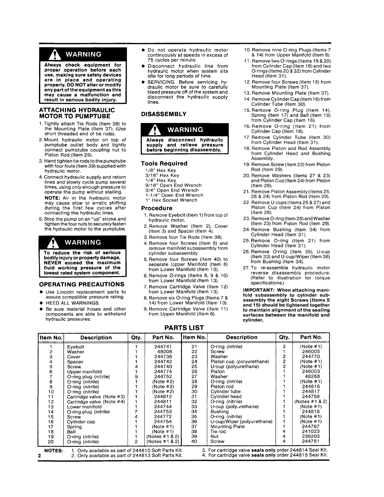
PARTS LIST
10. Remove nine O-ring Plugs (Items 7
&14) from Upper Manifold (Item 6).
11. Remove two O-rings (items 19 &20)
from Cylinder Cap (Item 16) and two
O-rings (Items 20&32) from Cylinder
Head (Item 31).
12. Remove four Screws (Item 15) from
Mounting Plate (Item 37).
13. Remove Mounting Plate (Item 37).
14. Remove Cylinder Cap(Item 16) from
Cylinder Tube (Item 30).
15. Remove O-ring Plug (Item 14),
Spring (Item 17) and Ball (Item 18)
from Cylinder Cap (Item 16).
16. Remove O-ring (Item 21) from
Cylinder Cap (Item 16).
17. Remove Cylinder Tube (Item 30)
from Cylinder Head (Item 31).
18. Remove Piston and Rod Assembly
from Cylinder Head and Bushing
Assembly.
19. Remove Screw (Item 22) from Piston
Rod (Item 29).
20. Remove Washers (Items 27 &23)
and Piston Cup(Item 24) from Piston
(Item 26).
21. Remove Piston Assembly (Items 25,
26 &24) from Piston Rod (Item 29).
22. Remove U-cups (Items 25&27) and
Piston Cup (Item 24) from Piston
(Item 26).
23. Remove O-ring (Item 28) and Washer
(Item 23) from Piston Rod (Item 29).
24. Remove Bushing (Item 34) from
Cylinder Head (Item 31).
25. Remove O-ring (Item 21) from
Cylinder Head (Item 31).
26. Remove O-ring (Item 35), U-cup
(Item 33) and U-cup/Wiper (Item 36)
from Bushing (Item 34).
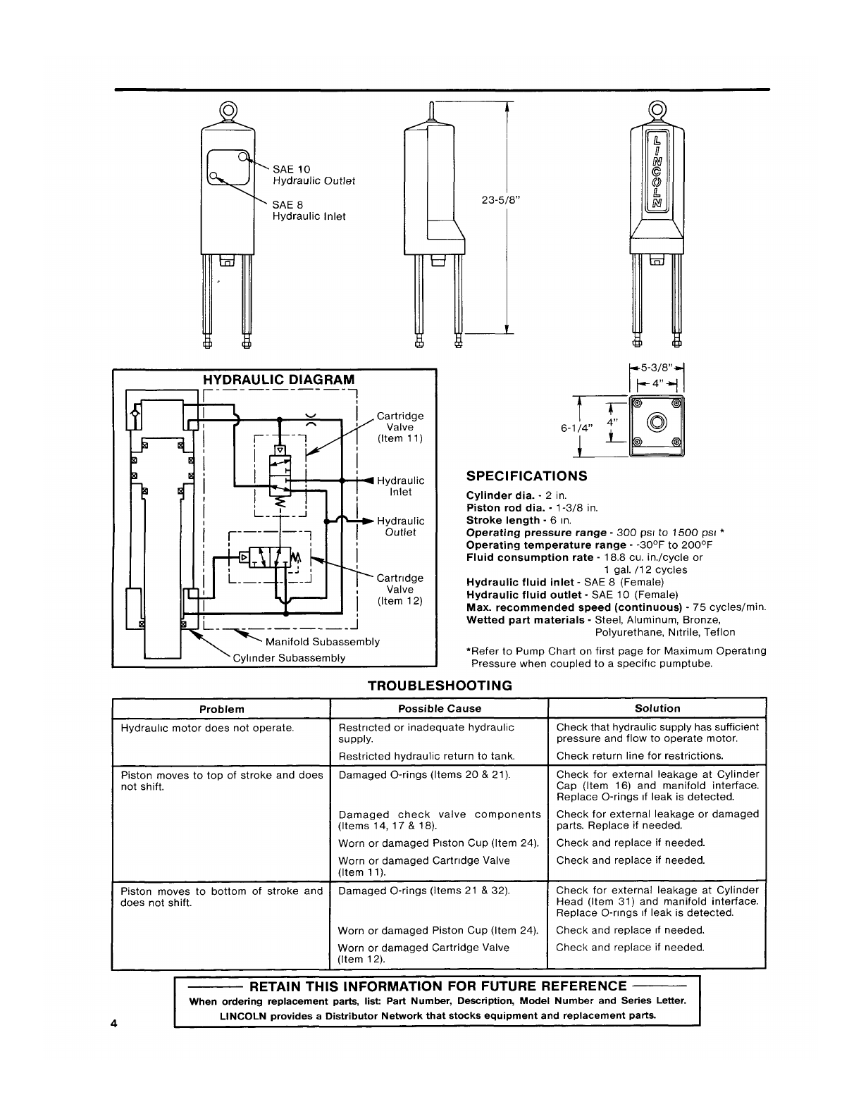
27. To re-assemble hydraulic motor
reverse disassembly procedure.
(Refer to Illustration for torque
specifications.)
IMPORTANT: When attaching mani-
fold subassembly to cylinder sub-
assembly the eight Screws (Items 5
and 15) should be tightened together
to maintain alignment of the sealing
surfaces between the manifold and
cylinder.
tern No. Description Qty. Part No. Item No. Description Qty. Part No.
1Eyebolt 1244741 21 O-ring (nitrile) 2
2Washer 148008 22 Screw (Note #1)
1 246005
3Cover 1244738 23 Washer 2244770
4Spacer 1 244742 24 Piston cup (polyurethane) 2
5Screw 4(Note #1)
244740 25 U-CUP (polyurethane) 2
6Upper manifold 1244774 26 (Note #1)
Piston 1
7O-ring plug (nitrile) 9244752 27 246003
Washer 1 48268
8O-ring (nitrile) 1(Note #2) 28 O-ring (nitrile) 1
9O-ring (nitrile) 1(Note #2) 29 (Note #1)
Piston rod 1244816
10 O-ring (nitrile) 1(Note #2) 30 Cylinder tube 1 244817
11 Cartridge valve (Note #3) 1244812 31 Cylinder head 1244758
12 Cartridge valve (Note #4) 1244811 32 O-ring (nitrile) 1
13 Lower manifold 1244744 (Notes #1 &2)
33 U-cup (polyurethane) 1(Note #1)
14 O-ring plug (nitrile) 7244753 34 Bushing 1 244818
15 Screw 4244772 35 O-ring (nitrile) 1
16 Cylinder cap 1244754 36 (Note #1)
U-cup/Wiper (polyurethane) 1
17 Spring 1(Note #1) 37 (Note #1)
Mounting Plate 1
18 Ball 1(Note #1) 38 244767
Tie rod 4 241023
19 O-ring (nitrile) 1(Notes #1 &2) 39 Nut 4 236203
20 O-ring (nitrile) 2(Notes #1 &2) 40 Screw 4 244751
NOTES: 1.Only available as part of 244810 Soft Parts Kit. 3. For cartridge valve seals only order 244814 Seal Kit.
22. Only available as part of 244813 Soft Parts Kit. 4. For cartridge valve seals only order 244815 Seal Kit.
To order call 1-800-548-1191 or visit www.partdeal.com - [email protected]
HYDRAULIC DIAGRAM
Problem
Hydraulic motor does not operate.
Piston moves to top of stroke and does
not shift.
Piston moves to bottom of stroke and
does not shift.
SPECIFICATIONS
Cylinder dia. -2in.
Piston rod dia. -1-3/8 in.
Stroke length -6in.
Operating pressure range -300 psi to 1500 psi *
Operating temperature range --30°F to 200°F
Fluid consumption rate -18.8 cu. in./cycle or
1gal. /12 cycles
Hydraulic fluid inlet -SAE 8(Female)
Hydraulic fluid outlet -SAE 10 (Female)
Max. recommended speed (continuous) -75 cycles/rein.
Wetted part materials -Steel, Aluminum, Bronze,
Polyurethane, Nitrile, Teflon
•Refer to Pump Chart on first page for Maximum Operating
Pressure when coupled to aspecific pumptube.
TROUBLESHOOTING
Possible Cause
Restricted or inadequate hydraulic
supply.
Restricted hydraulic return to tank.
Damaged O-rings (Items 20 &21).
Damaged check valve components
(Items 14, 17 &18).
Worn or damaged Piston Cup (Item 24).
Worn or damaged Cartridge Valve
(Item 11).
Damaged O-rings (Items 21 &32).
Worn or damaged Piston Cup (Item 24).
Worn or damaged Cartridge Valve
(Item 12).
Solution
Check that hydraulic supply has sufficient
pressure and flow to operate motor.
Check return line for restrictions.
Check for external leakage at Cylinder
Cap (Item 16) and manifold interface.
Replace O-rings if leak is detected.
Check for external leakage or damaged
parts. Replace if needed.
Check and replace if needed.
Check for external leakage at Cylinder
Head (Item 31) and manifold interface.
Replace O-rings if leak is detected.
Check and replace if needed.
RETAIN THIS INFORMATION FOR FUTURE REFERENCE
When ordering replacement parts, list Part Number, Description, Model Number and Series Letter.
LINCOLN provides aDistributor Network that stocks equipment and replacement parts.
4
To order call 1-800-548-1191 or visit www.partdeal.com - [email protected]

This manual suits for next models

1

Other Pentair Engine manuals

Pentair P42B0007A2-01 User manual

Pentair

Pentair P42B0007A2-01 User manual

Pentair HYPRO HM1C User manual

Pentair

Pentair HYPRO HM1C User manual

Pentair PENTEK 76PM2-50-4 User manual

Pentair

Pentair PENTEK 76PM2-50-4 User manual

Pentair Pentek Series User manual

Pentair

Pentair Pentek Series User manual

Popular Engine manuals by other brands

Engine distributors CSG 637 Operator's handbook

Engine distributors

Engine distributors CSG 637 Operator's handbook

Volvo Penta D1-20 Operator's manual

Volvo Penta

Volvo Penta D1-20 Operator's manual

Isuzu 4HK-1 manual

Isuzu

Isuzu 4HK-1 manual

Stiga WBE120 Operator's manual

Stiga

Stiga WBE120 Operator's manual

SEW-Eurodrive MOVIMOT MMxD Series operating instructions

SEW-Eurodrive

SEW-Eurodrive MOVIMOT MMxD Series operating instructions

3W 24i CS manual

3W

3W 24i CS manual

Nice For-Max Pro Instructions and warnings for installation and use

Nice

Nice For-Max Pro Instructions and warnings for installation and use

Vertilux VTi 35 Series Programming instructions

Vertilux

Vertilux VTi 35 Series Programming instructions

Francis A2651 User instruction & installation manual

Francis

Francis A2651 User instruction & installation manual

CHICAGO 03068 Assembly instructions

CHICAGO

CHICAGO 03068 Assembly instructions

Robin America EH72 Instructions for use

Robin America

Robin America EH72 Instructions for use

Schiller STEINER 75-70006A Operator's manual

Schiller

Schiller STEINER 75-70006A Operator's manual

O.S. engine MAX-61LX Owner's instruction manual

O.S. engine

O.S. engine MAX-61LX Owner's instruction manual

Perkins 6.3544 Series User handbook

Perkins

Perkins 6.3544 Series User handbook

SOMFY WireFree RTS Quick programming guide

SOMFY

SOMFY WireFree RTS Quick programming guide

Sears 143.001302 Operator's manual

Sears

Sears 143.001302 Operator's manual

Vexta SMK216A-GN instructions

Vexta

Vexta SMK216A-GN instructions

Kohler Lombardini 12 LD 477-2 Use & maintenance

Kohler

Kohler Lombardini 12 LD 477-2 Use & maintenance

manuals.online logo
manuals.online logoBrands
  • About & Mission
  • Contact us
  • Privacy Policy
  • Terms and Conditions

Copyright 2025 Manuals.Online. All Rights Reserved.