Pentair Raychem NGC-UIT2-0RD User manual

NGC-UIT2-ORD
installed in a panel
DESCRIPTION
The NGC-UIT2-ORD is a panel mounted display used in conjunction
with other Raychem control and monitoring devices. The NGC-UIT2-
ORD is rated IP 65 (Type 4), and can be mounted indoors or outdoors.
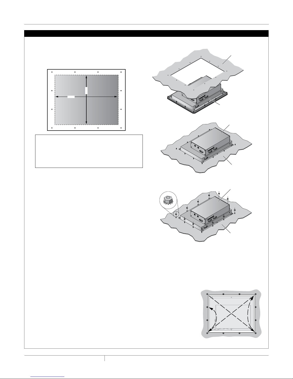
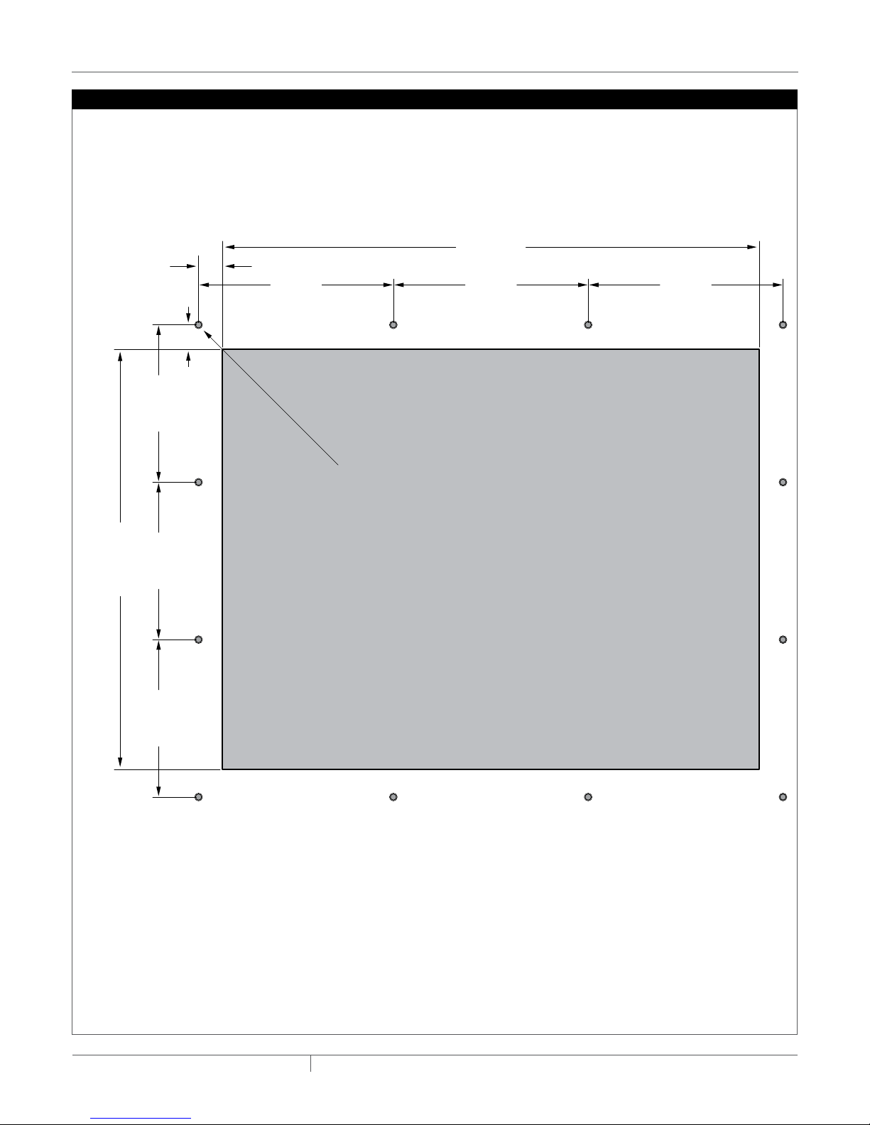
The NGC-UIT2-ORD kit includes all hardware required for mounting
in a suitable electrical panel. Additional materials are required for
electrical connections and are detailed below. These instructions
describe how to mount the NGC-UIT2-ORD in an electrical panel and
are intended only for personnel experienced in panel construction.
TOOLS REQUIRED
• Maskingtape • #16(3/16)drillbit
• Metalfile
• In-linetorquewrenchwith8mm(5/16in)socket
• Jigsaw(recommendusingcarbonsteelbladewith24TPI)
ADDITIONAL MATERIALS (TO BE ORDERED SEPARATELY)
Qty Description Manufacturer
Manufacturer
Part Number
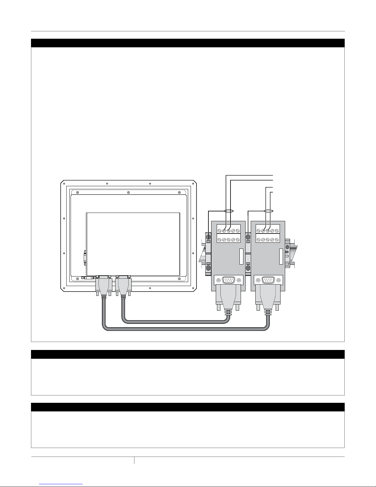
29pinD-SUBto10pinterminal
block PCB
Phoenix Contacts 2315162
2 Serial communication cable L-COM CSMN9MF-xx
xx = Length in ft
3 Alarmrelays–12Vdc,12A,
SPDT
Tyco Electronics RTB14012F
3Alarm relay sockets Tyco Electronics RT78724
1 Pushtotestalarmlight120or230Vac
Note: Equivalent parts may be used.
FIRE HazaRd: The NGC-UIT2-ORD must not be used in hazardous
locations. Electrical components within the unit could ignite
flammable gases. Do not install the unit where it may be exposed
to flammable gases.
The NGC-UIT2-ORD is an electronic unit. During installation, take the
following precautions to avoid damage to its electronic components.
• Handlewithcaretoavoidmechanicaldamage.
• Keepelectronicsdry.
• Avoidexposuretostaticelectricity.
• Avoidcontaminationwithmetalfilings,liquids,orotherforeign
matter.
• Takecaretoprotecttheuserinterfaceboardontheenclosuredoor.
• Useagency-approvedconduitbushings,adapters,andcable
glands to keep the enclosure protected from dust and fluids.
WARNING: IMPORTANT:
General
Area of Use Nonhazardous, indoors or outdoors
(IP65, Type 4)
SupplyVoltage 9–30Vdc,3.6–1.2A
Operating
Temperature
–30°Cto50°C(–22°Fto122°F)
Min.Storage
Temperature
–30°Cto80°C(–22°Fto176°F)
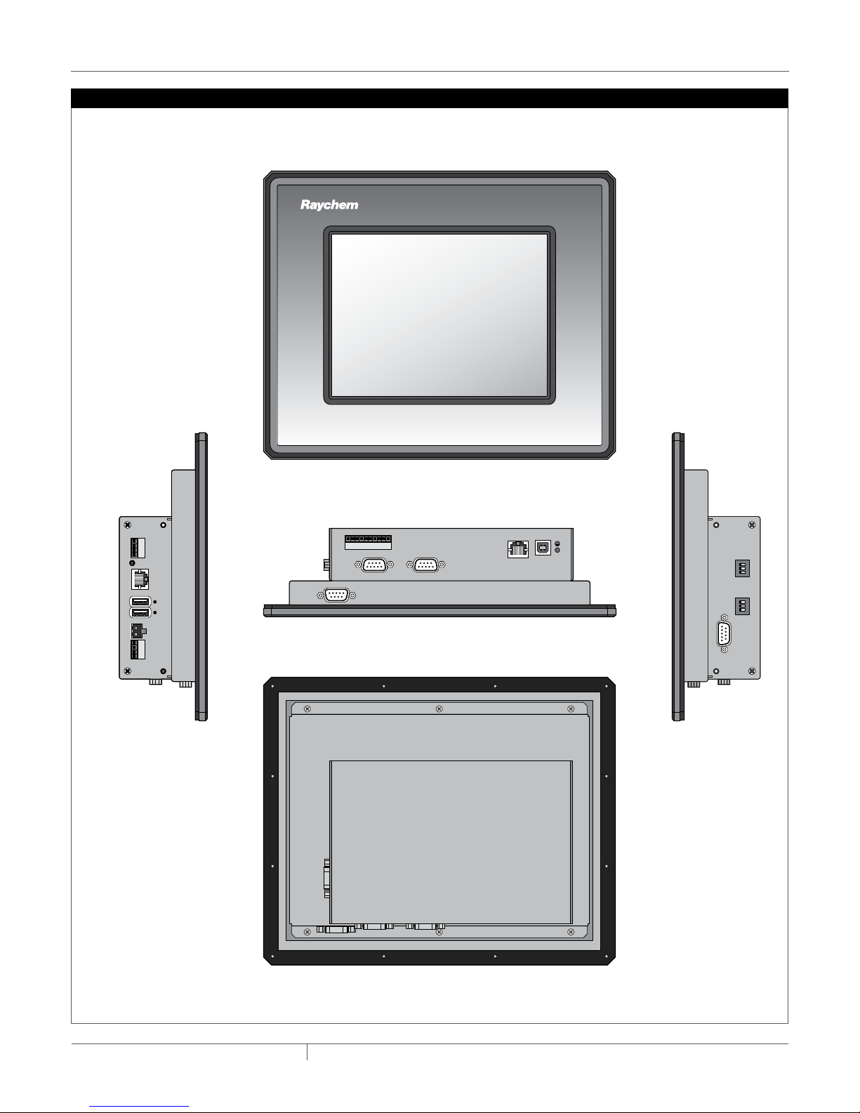
Dimensions 279mmWX229mmHX70mmD
(11in.WX9in.HX2.75in.D)
Alarm Outputs
Transistor open
collector outputs
Threeopencollectoroutputs,witharangeof5–30
Vdcwithamax.sinkcurrentof500mA
Use to drive
external relays
Relays may be assigned for alarm outputs.
LCD Display
Display LCDisa8.4in.XGA,colorTFTtransectivedevice
with integral LED backlight
Touch Screen 5-wire resistive touch screen interface for user entry
Network Connection
Local/
Remote Port
RS-232/RS-485portsmaybeusedtocommunicate
with host computers (Raychem Supervisor Software)
or DCS
LocalRS-232 A non-isolated, 9 pin D sub male
RemoteRS-485#2 2-wire isolated, 9 pin D sub male
Data Rate 9600to57600baud.
Maximumcable
length
ForRS-485nottoexceed1200m(4000ft).Cableto
be shielded twisted pair.
FieldPort RS-485,2-wireisolated.Usedtocommunicatewith
externaldevices,suchasNGC-30-CRMandRMM2.
Maximumcablelengthnottoexceed1200m(4000
ft). Cable to be shielded twisted pair.
FieldRS-485#1 2-wire isolated, 9 pin D sub male
Data Rate To9600baud
LAN 10/100Base-TEthernetportwithLinkandActivity
Status LEDs
USB Ports USB2.0HostportTypeAreceptacle(X2)
APPROVALS / CERTIFICATIONS
3128486
CONFORMS TO UL STD 60950-1
CERTIFIED TO CSA STD C22.2
NO. 60950-1
Nonhazardous Locations
1/8
GB-RaychemNGCUIT20RD-IM-H58531INSTALL-16805/15
INDUSTRIAL HEAT TRACING SOLUTIONS
NGC-UIT2-ORD
User Interface termInal for raychem nGc systems InstallatIon InstrUctIons

2/8
GB-RaychemNGCUIT20RD-IM-H58531INSTALL-16805/15
INDUSTRIAL HEAT TRACING SOLUTIONS
KIT CONTENTS
Qty Description
1 NGC-UIT2-ORD
12 6/32inKepnuts(lockingnuts)
1 5-ft9-pinRS-232(NullModem)cable
C1
CB19
CB17
CB15
CB13
CB3
CB9
CB11
CB7
CB5
CB1
CB16
CB42
CB20
CB18
CB4
CB14
CB12
CB10
CB8
CB6
CB2
C2 C3 C4 C5 C6 C7 C8 C9 C10
CB23
CB25
CB27
CB29
CB21
CB26
CB28
CB30
CB22
CB24
CB31
CB33
CB35
CB37
CB39 CB40
CB36
CB32
CB34
CB38
1
3
5
7
9
19
17
15
13
11
29
27
25
23
21
39
37
35
33
31
2
4
6
8
10
12
14
16
18
20
30
28
26
24
22
32
34
36
38
40
PanelNGC-UIT2-ORD
assembly location
Panel
door
Alarm
light
Provide Suitable Panel Enclosure, and Determine Locations for NGC-UIT2-ORD Assembly in Panel
1. Provide suitable panel enclosure
To protect its electronic components, the NGC-UIT2-ORD
must be mounted in a non-hazardous location panel with a
minimumIP32(Type1)enclosure.AnIP52(Type12)orbetter
enclosure is recommended. The NGC-UIT2-ORD assembly
comes with a sealing gasket and hardware to mount the
enclosure.
Note: The Raychem NGC-UIT2-ORD is designed for opera-
tioninambienttemperaturesfrom–30°Cto70°C(–22°Fto
158°F).Iftheambienttemperatureisoutsidethisrange,a
spaceheaterand/orcoolingfanwillberequiredinthepanel.
2. Determine locations for the NGC-UIT2-ORD assembly in
the electrical panel
The NGC-UIT2-ORD should be located on the front of the
panel near eye level (for convenient viewing). The NGC-UIT2-
ORD assembly is an electronic unit and must not be located
where it will be exposed to strong magnetic fields or exces-
sive vibration.

3/8
GB-RaychemNGCUIT20RD-IM-H58531INSTALL-16805/15
INDUSTRIAL HEAT TRACING SOLUTIONS
Cut Opening and Mount NGC-UIT2-ORD on Front of Panel
1. Locate the NGC-UIT2-ORD on front of panel
Locate the NGC-UIT2-ORD assembly on the front of the
panelatalevelconvenientforviewing.Makesurethecover
on the back of the assembly will not interfere with existing
panel hardware.
2. Prepare and mark the position of the display opening and
mounting holes
• Usethecut-outdirectionstolayouttheopeningforthe
NGC-UIT2-ORD display.
• Applytwolayersofmaskingtapearoundtheouterpe-
rimeter of the intended opening to prevent scratching the
panel surface with the jigsaw.
3. Cut the display opening
Cut the opening for the NGC-UIT2-ORD with a jigsaw using
a 24 TPI blade. Take care not to damage the panel door.
Remove all rough edges and burrs with a metal file before
proceeding.
4. Drill the mounting holes
Drillthe12holeswitha#16(3/16in)drillbittomountthe
NGC-UIT2-ORD assembly in the panel.
Note: The following steps are most easily accomplished if
the panel door is on a horizontal surface.
5. Mount the user interface assembly onto the panel door
•Place the NGC-UIT2-ORD assembly in position; the twelve
studs go through the twelve holes on the NGC-UIT2-ORD
assembly mounting plate (see figure below).
• Placethesupplied6/32inKepnutsoneachofthetwelve
mountingstuds.Fastenonlyhandtight.
• Lookatthefrontofthepanel,andaligntheNGC-UIT2-
ORD assembly so it is level (loosen nuts if necessary to
reposition the NGC-UIT2-ORD assembly).
• Afterthedisplayisproperlypositioned,tightenthenuts
to0.9newton-meters(8inch-pounds)oftorqueusinga
8mm(5/16in)in-linetorquewrench. Do not overtighten
and risk damage to hardware.
• Tighten Kep nuts in the sequence shown for proper
sealing.
Cutting
Area
9.588 in
7.508 in
Note: Cutting the opening for the display is a craft sensi-
tive procedure; if it is not done correctly, the panel door
can be damaged. The procedure for laying out and cutting
the opening for the display must be undertaken with
care, and by personnel qualified and experienced in panel
construction.
Panel door
NGC-UIT2-ORD display
with sealing gasket
Inside of
panel door
NGC-UIT2-ORD
display
Inside of
panel door
NGC-UIT2-ORD
display

4/8
GB-RaychemNGCUIT20RD-IM-H58531INSTALL-16805/15
INDUSTRIAL HEAT TRACING SOLUTIONS
190.7 mm
(7.508 in)
10.82 mm
(0.426 in)
88.39 mm
(3.480 in)
Ø 4.83 mm (0.190 in) X12
71.48 mm
(2.814 in)
71.48 mm
(2.814 in)
71.48 mm
(2.814 in)
Panel Cut Out Area
Top of Display
Drawing
NOT TO SCALE
Drawing
NOT TO SCALE
11.1 mm
(0.437 in)
88.39 mm
(3.480 in)
88.39 mm
(3.480 in)
243.54 mm
(9.588 in)
Panel Cut Out
Panel Cut Out
NGC-UIT2-ORD Cut Out Dimensions

5/8
GB-RaychemNGCUIT20RD-IM-H58531INSTALL-16805/15
INDUSTRIAL HEAT TRACING SOLUTIONS
Bottom view
Back view
Front view
RS-485-2
Debug Port (not used)
Ethernet
USB device port
(not used)
Open Collector Outputs
RS-485-1
Side view Side view
RS-232
RS-485-1
Termination
RS-485-2
Termination
USBPower
RS-485
(not used)
CAN
(not used)
RS-485
(not used)
NGC-UIT2-ORD Connection Diagram

6/8
GB-RaychemNGCUIT20RD-IM-H58531INSTALL-16805/15
INDUSTRIAL HEAT TRACING SOLUTIONS
+12 Vdc input
9-30 Vdc
GND
Door Mounted
+12 Vdc
These relays are shown
in the energized position
without an alarm condition.
120 or 230 Vac
Neutral
GND (–)+12 Vdc
Input
+87654321–
+87654321–
NO
C
NC
NO
C
NC
NO
C
NC
3
4
Alarm
Lamp
120 or 230 V Lamp
IDEC SWITCH/
LAMP 1
2
Relay Driver Output
Relay Driver Output
Alarm Relays
Jumper switch
terminals 1, 4 and x2
Connect Power
Install Common Alarm Light and Alarm Relays
Connect12Vdctothemalepowerconnectionfittinglocatedon
the left side of the NGC-UIT2-ORD. The “+” lead should go to the
terminalmarked“9–30Vdc” and the “–” lead should go to the
terminal marked “GND”.
Note:TheNGC-UIT2-ORDisratedfor9–30Vdc.SincetheNGC-
30-CRMmodulesareratedfor12Vdc,wehaveusedthisvoltage
to also power the NGC-UIT2-ORD. As a result, the recommend
alarmrelaysandlightsdetailedinthe“AdditionalMaterials”are
ratedfor12Vdc.
Mountthe3alarmrelaysonaDINrailinsidethepanelenclosure.
MounttheAlarmlightonthepanel’sdoorbelowthetouchscreen.
Perthebelowdrawing,bring12VdctotheRelayDriverOutputat
the bottom of the touch screen, to the alarm relays and alarm light.
Per the below drawing, wire between the Relay Driver Output,
alarm relays, and alarm light.

7/8
GB-RaychemNGCUIT20RD-IM-H58531INSTALL-16805/15
INDUSTRIAL HEAT TRACING SOLUTIONS
To CRM/S,
RMM or
NGC-20
To host
computer
Data +
Shield
Data –
54321
T 9 8 7 6
Field Port
RS-485-1
Data +
Shield
Data –
Remote Port
RS-485-2
Remote Port
Field Port
Back Side of UIT
RS-485-2 RS-485-1
54321
T 9 8 7 6
Communication
TheNGC-UIT2-ORDhastwoisolatedRS-485portslocatedat
the bottom.
Field Side Port (RS-485-1)
TheRS-485portlabeled“RS-485-1”isthefieldsideport
thatisusedtocommunicatewithModBusdevices(ie.NGC-
30-CRM/S,RMM2andNGC-20).
Host Port (RS-485-2) – Optional
TheRS-485portlabeled“RS-485-2”istheHostsideport
that is used to communicate with to a host computer (using
Raychem Supervisory Software) or to a DCS.
Local Host Port (RS-232) – Optional
TheRS-232portcanbeusedaslocalHostportthatisused
to communicate with to a host computer (using Raychem
SupervisorySoftware).IftheRS-232portisutilized,the
supplied female to female, 9-pin null modem adaptor cable
must be used.
Connection
ThewiringconnectiontobothRS-485-1andRS-485-2arethe
same.
Installthetwo9pinD-SUBto10pinterminalblockonaDIN
rail inside the panel enclosure. (Note: These should be placed
were the Serial cable from the bottom of the NGC-UIT2-ORD
mounted on the panel door can be easily accessible).
Connect one end of the Serial communication cables to the
portslabeledRS-485-1andRS-485-2onthetouchscreenand
theotherendstothe9pinD-SUBto10pinterminalblock.
(Note: The lengths of Serial communication cables are based
upon were the touch screen is located and the 9 pin D-SUB to
10pinterminalblock.Youshouldlocatethesepartsfirst,mea-
sure, and then purchase your Serial communication cables).
Usingashielded,twistedpaircable(BeldenCDTcable8761
orequivalent,maximumlengthis1219meters(4000feet),
connecttoterminals3(–)and4(+)onthe9pinD-SUBto10pin
terminal blocks taking note of the polarity.
The NGC-UIT2-ORD contains no user-serviceable parts. Contact
your Pentair Industrial Heat Tracing Solutions representative for
service and an authorization number if required.
The touch screen area of the NGC-UIT2-ORD may be cleaned
with a damp or dry cloth. Typical window cleaning agents may be
applied to aid in the removal of dirt, dust and grease. Do not use
abrasive cleaners.
Servicing
Cleaning

© 2010-2015 Pentair.
NORTH AMERICA
Tel: +1.800.545.6258
Fax: +1.800.527.5703
Tel: +1.650.216.1526
Fax: +1.650.474.7711
thermal.info@pentair.com
EuROpE, MIddlE EAsT, AfRICA
Tel: +32.16.213.511
Fax: +32.16.213.603
thermal.info@pentair.com
AsIA pACIfIC
Tel: +86.21.2412.1688
Fax: +86.21.5426.2937
cn.thermal.info@pentair.com
lATIN AMERICA
Tel: +1.713.868.4800
Fax: +1.713.868.2333
thermal.info@pentair.com
Pentair and NGC are owned by Pentair or its global affiliates. All other trademarks are the property of their respective owners. Pentair reserves the right
to change specifications without prior notice.
WWW.PENTAIRTHERMAL.COM
8/8
GB-RaychemNGCUIT20RD-IM-H58531INSTALL-16805/15
INDUSTRIAL HEAT TRACING SOLUTIONS
Reset
RS-485-1
Termination
Pull-down
Pull-up
Termination
3 2 1
ON
RS-485-2
Termination
RS-485 configuration switches
Reset switch
The configuration switches are found on the right side of the
NGC-UIT2-ORD. Refer to the table below for settings.
The Reset switch can be found on the side of the NGC-UIT2-ORD. A
pointed object is required to press the reset switch and restart the
NGC-UIT software.
Position
Switch On Off Comments
Pull-down (As-shippeddefault)RS-485network
“–” signal is forced to a determinate
state when idle.
RS-485network“–”signalisnot
forced to a determinate state when
idle.
One device (typically this NGC-UIT2-ORD) on the
RS-485networkshouldforcethenetwork“-“signal
to a determinate state.
Pull-up (As-shippeddefault)RS-485network
“+” signal is forced to a determinate
state when idle.
RS-485network“+”signalisnot
forced to a determinate state when
idle.
One device (typically this NGC-UIT2-ORD) on the
RS-485networkshouldforcethenetwork“+“signal
to a determinate state.
Termination (As-shippeddefault)RS-485network
isterminatedwith120-ohmresistor.
RS-485networkisnotterminated. Terminate the device (NGC-UIT2-ORD or other) that
isateachendoftheRS-485network,foratotalof
two terminated devices. No other devices on the
network should be terminated.
Table of contents
Other Pentair Recording Equipment manuals