Pentair SCREENLOGIC INTERFACE User manual

SCREENLOGIC®INTERFACE Wireless Connection Kit Installation Guide
IMPORTANT SAFETY INSTRUCTIONS
READ AND FOLLOW ALL INSTRUCTIONS
SAVE THESE INSTRUCTIONS
INSTALLATION GUIDE
SCREENLOGIC®INTERFACE
WIRELESS CONNECTION KIT
FOR INTELLITOUCH®AND EASYTOUCH®CONTROL SYSTEMS

SCREENLOGIC® INTERFACE Wireless Connection Kit Installation Guide
Technical Support
Phone:(800)831-7133
Websites: visit www.pentairpool.com and www.staritepool.com
Contents
Overview ...........................................................................................................1
WirelessConnection Kit Contents ......................................................................1
SummaryInstallationSteps ................................................................................2
ScreenLogicInterfaceConnection Diagram .......................................................3
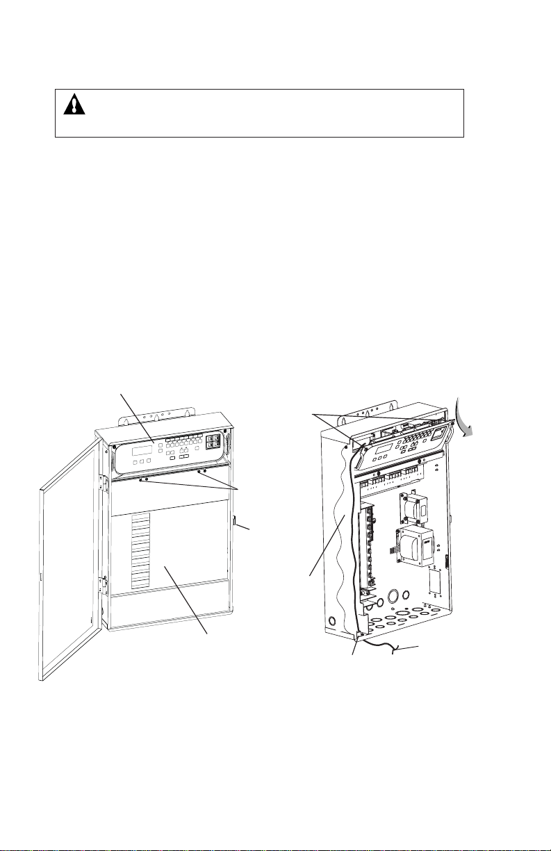
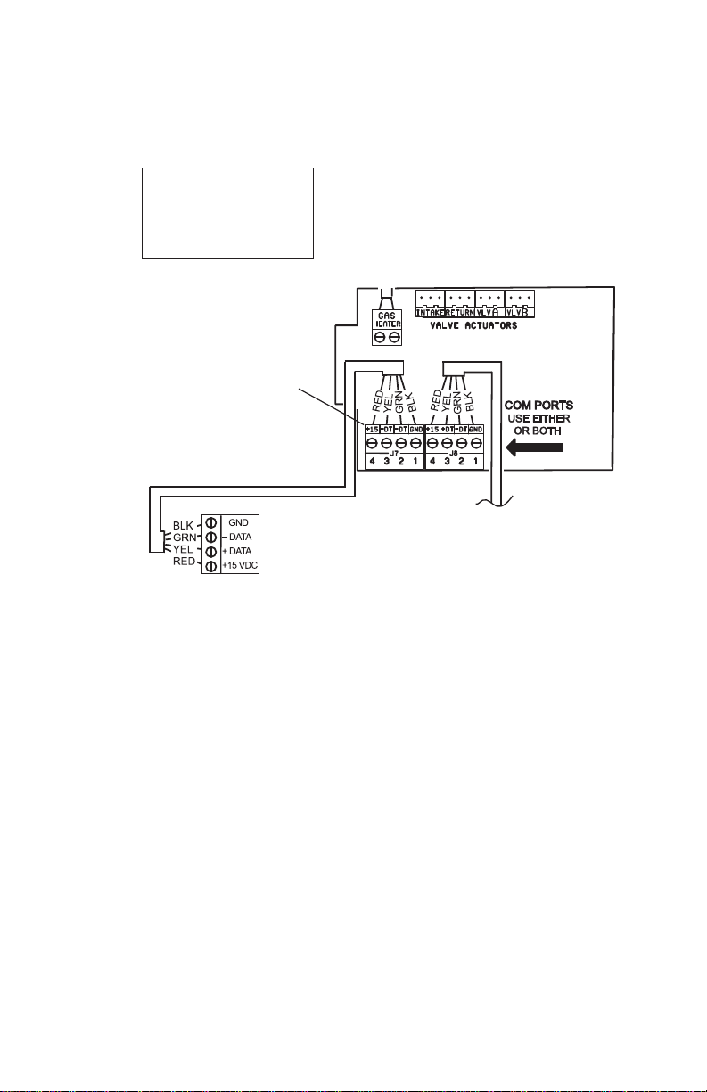
Mountthe OutdoorWirelessTransceiverandConnect tothe
IntelliTouchor EasyTouch Load Center ..............................................................4
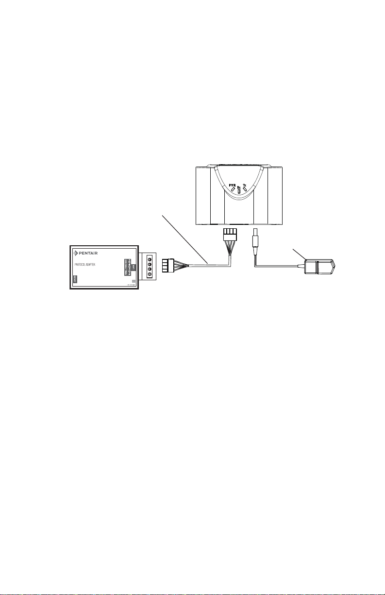
Connect the IndoorWireless Transceiver to the ScreenLogic
Interface Protocol Adapter .................................................................................8
Connectthe IndoorWirelessTransceiverto theScreenLogic
Interface Protocol Adapter .................................................................................8
Cradle/Desk Mount the IndoorWirelessTransceiver ........................................... 8
WallMountthe IndoorWirelessTransceiver........................................................8
i
FCC Regulatory Safety Notice
This equipment has been tested and found to comply with the limits for a Class B digital
device, pursuant to Part 15 of the FCC Rules.These limits are designed to provide
reasonable protection against harmful interference in a residential installation.This
equipment generates, uses and can radiate radio frequency energy and, if not installed
and used in accordance with the instructions, may cause harmful interference to radio
communications.However, there is no guarantee that interference will not occur in a
particular installation. If this equipment does cause harmful interference to radio or television
reception, which can be determined by turning the equipment off and on, the user is
encouraged to try to correct the interference by one or more of the following measures:
• Reorient or relocate the receiving antenna.
• Increase the separation between the equipment and receiver.
• Connect the equipment into an outlet on a circuit different from that to which the
receiver is connected.
• Consult the dealer or an experienced radio/TV technician for help.
• Modifications not expressly approved by the party responsible for FCC compliance
could void the user’s authority to operate the equipment.
Industry Canada Statement
The device complies with industry Canada’s License Exempt RSSs.Operation is subject to the
following:(1)This device may not cause interference;and (2) This device must accept
interference that may cause undesired operation of the device.
This Class B digital apparatus complies with Canadian ICES-003.Cet appareil numérique de la
classe B est conforme à la norme NMB-003 du Canada.The term “IC”before the certification /
registration number only signifies that the Industry Canada technical specifications were met.
Le dispositif est conforme à la licence d'Industrie Canada Exempt CNR. Le fonctionnement est
soumis à la suivante. (1) Ce ne doit pas provoquer d'interférences ; et (2) Cet appareil doit
accepter les interférences qui peuvent causer un mauvais fonctionnement de l'appareil.
Notice: In order to comply with FCC RF Exposure requirements, a minimum separation
distance of 8 in (20 cm) must be maintained between the equipment and all persons during
normal operation.

SCREENLOGIC®INTERFACE Wireless Connection Kit Installation Guide
1
ScreenLogic®Interface Wireless Connection Kit Overview
The ScreenLogic®InterfaceWireless Connection interface consists of an
indoor and outdoor wireless 902-928 MHz wireless transceiver.
Note:The wireless transceivers ship from the factory as a matched pair.
The ID numbers on each transceiver must be the same number to function
correctly.If needed, the transceivers are replaced as a matched pair .For
moreinformation, callCustomer Support(880) 831.7133.
The indoor and outdoor transceivers provide a wireless connection
between the ScreenLogic Interface Protocol adapter and the IntelliTouch®
or EasyTouch® Control System Load Center located at the equipment pad.
This wireless connection eliminates the existing hard wire connection from
insideyour hometo theequipment pad.
4X
Mounting hardware
2X
Outdoor
Transceive
r
enclosure
Indoor transceiver and base
AC transformer
Outdoor Cable
(white - 10 ft.)
NOTE (*):ID numbers
on Indoor and Outdoor
transceiver board must
match
Indoor hardware
Cable (for connection to
ScreenLogic
®
Interface
ProtocolAdapter
(purchased separately)
2X 4X
2X
In this Installation Guide
ThisInstallation Guide providesinstallation instructions forthe ScreenLogic®
InterfaceWireless Connection kit.
• Forthe ScreenLogic Interface system operatinginstructions, refer tothe
ScreenLogicInterfaceUser’s Guide(P/N 520493)
SCREENLOGIC INTERFACE
®
ScreenLogicInterface
ProtocolAdapter
(purchasedseparately)
ScreenLogic Interface Wireless Connection Kit Contents
Wireless Connection Kit Contents
Thefollowingitems are includedintheWirelessConnection kit:
•One ScreenLogic Interface indoor wireless transceiver with AC power
adapterand 1 ft.longcable with attachedplugs.
• OneScreenLogic Interface outdoor wireless transceiverwith
10ft.cable, enclosure and mountinghardware.
• ScreenLogicInterfaceWirelessConnection InstallationGuide
(thismanual).

SCREENLOGIC® INTERFACE Wireless Connection Kit Installation Guide
2
Antennalocation
IndoorWirelessTransceiver
PWR:Green LED on:Power is on to the unit.
• PWR LED blinking: Not linked or lost link,
attempting to link or relink, no response.
•PWR LED blinking, TXand/or RXLED blinking:
notlinked, attempting to link, gettingresponses.
•PWR LED on steady: Linked.
•PWR LED blinking: Lost link, Attemptingto relink.
RX:YellowLEDindicates the unit is receiving data.
TX: GreenLED indicates theunit is transmittingdata.
Note:ScreenLogicInterfaceIndoorWirelessTransceiver(Note:Foroptimum
performance,mount indoor transceiverupright in thecradle or onanindoor
wall).
Summary Installation Steps
TheScreenLogic®Interface connectiondiagram on page3 shows the
transceiverlocations and connections.To install theScreenLogic Interface
WirelessConnection kit:
RS-485Connector
(toProtocol Adapter)
• Mounttheoutdoor transceiverantennamodulenear the IntelliTouch®
or EasyTouch®Control System Load Center (see page 4 for
mountinginstructions). Using the provided10 ft. cable,connect the
transceiver to the COM port connector located in the IntelliTouch or
EasyTouchControl System Load Center (see page 7).
• Connectthe ScreenLogic Interface indoor wirelesstransceiver to the
ScreenLogicInterface Protocol adapterusing the 12incable. Plug
theAC power adapter into anAC wall-outlet andinto thewireless
transceiverunit topower upthe unit(see page8).
ID number
(Outdoor transceiver)
IMPORTANT NOTICE:Be sure the
yellow ID label (9-digit ID number
XXXXXXXXX) located to the right of
the RS-485 connector on the front side
of the Indoor transceiver
enclosure and the ID number
on the ScreenLogic Interface Outdoor
Wireless transceiver are the same. See
page 1 for label location.
LED Indicators Description:

SCREENLOGIC®INTERFACE Wireless Connection Kit Installation Guide
1234
WAN
RJ11 RJ45
INTERNET
1234
WAN
- LAN -
Wiredor wireless
router
(mandatory)
RJ11 for DSL
Coax for Cable
In-wall Touch
Screen
OutdoorWireless
transceiverconnected to
COM PORT on main circuit
board via 10 ft. cable
Protocol
Adapter
ScreenLogic®
Interface
Wireless router
Existing PC
Ethernet cable(RJ45-CAT 5)
Ethernet cable
(RJ45 - CAT 5)
DSL or
Cable Modem
(RJ45)
Cable distance limits:
- Ethernet cable distance limit = 300 feet
- Four-wire cable distance limit = 1500 feet
Note:(*) Optional wiringfor existing Indoor
Control Panel.Tap into the Indoor Control
Panel connector or pig tail off the four-wire
cable connected to the Control System Board.
IndoorTransceiver
connectedto
ScreenLogic
Interface
Protocoladapter
EasyTouch®,
IntelliTouch®Control
Systems Load
Center
(Located outside at
equipment pad)
3
4-wire
one foot
cable
AC power
adapter
ScreenLogic®Interface Connection Diagram
IntelliTouch®or
EasyTouch®Indoor
ControlPanel(*)

SCREENLOGIC® INTERFACE Wireless Connection Kit Installation Guide
4
Mount the Outdoor Wireless Transceiver and Connect to the
IntelliTouch®or EasyTouch®Control System Load Center
Thefollowing describes howto mount and connect theoutdoor transceiver
tothe IntelliTouch or EasyTouchControlSystem Load Center.
Mounting the Outdoor Transceiver Module
The outdoortransceiver isa two-wayradio devicewith anattached antennathat
communicateswiththe IntelliTouch orEasyTouch Control Systemvia the
10ft.four-conductorcommunication cable.
Outdoor tranceiver mounting location: Choosea convenient locationon a flat
vertical surface near the Load Center at a minimum of 5 ft above ground level to
optimizethetransmit and receiveoperatingrange.For optimum performance
positionthe Outdoor transceiver withan unobstructed line-of-sightpropagation
betweentheIndoorand Outdoor tranceiver.
1. Position thebackplate against themounting surfaceso that the
transceiver is oriented in an upright position with the antenna
pointing upwards. Use a pencil to mark the four mounting points.
Drill four3/16 in.diameter holes intothe mounting surfaceand insert
thefour plastic anchors provided inthe kit.
Note:To avoid signal interference, mount the transceiver a
minimum of 10 feet away from the load center, any metal
surface/structure, or air blower located in the immediate area
of the equipment pad.
2. Position thebackplate overthemounting points and secure it with
thefour mountingscrews provided in the kit.
3. Carefullyposition the transceiver circuit boardinto the mountedback
plate.Route the communicationcablewire up throughthe lower exit
holeat the bottomofthe back plate.Carefully pull thecommunication
cableout the lower hole andposition thecircuit board inthe back
plate.
4. Proceedto “Connect the wireless transceiver communication
cable to the COM Port on automation control systems circuit
board”onpage 6.
5. Slidethe case overthe circuitboard and antennainto the back plate.
Secure the circuit board in the case using the two retaining screws.

SCREENLOGIC®INTERFACE Wireless Connection Kit Installation Guide
5
Outdoor Wireless Transceiver
Case
Wireless transceiver
case retaining
screws (x2)
Back plate for
mountingcircuit
board
Outdoor wireless transceiver
circuit board
Connect 4-conductor
communication cable to
terminal screws.
Outdoor
Transceiver
connector
COM PORT (RS-485)
screw terminal connector on
IntelliTouch®or EasyTouch®
Control System circuit board
BLK
RED
YEL
GRN
BLK (GND - PIN 1)
GRN (- DT - PIN 2)
YEL (+ DT - PIN 3)
RED (15 V - PIN 4)
Outdoor
Transceiver
circuit
board

SCREENLOGIC® INTERFACE Wireless Connection Kit Installation Guide
WARNING Switch OFF the main power to the Load Center
before making any connections.
1. Switch OFF the AC power to the enclosure at the main house panel
circuitbreaker.
2. Unlatchthe front door latch andopen the front door.Removethe two
retainingscrewsfromthe High-VoltageCover Paneland remove the
panel.
3. Loosenthe tworetaining screws securing from thetop edgeof the
OutdoorControl Panel.FolddowntheOutdoorControl Panel to
access the circuit board sockets connectors for the electrical
connections.Remove the panelfromthe enclosure (seeillustration
below).
4. Routethe four conductor transceiver connectioncable into the lower
plasticgrommet, upthrough the low voltage racewayto thesystem
circuitboard.
6
Connect the wireless transceiver communication cable to the COM
Port on automation control system circuit board
IntelliTouch®or EasyTouch®ControlSystem Load Center
Retaining
screws
HIGH -VOLTAGE
FRONTCOVER
PANEL
Outdoor
ControlPanel
retaining
screw (x2)
Outdoor
transceiver
communication
cable
(connectto
COM port)
Outdoor
ControlPanel
Grommet
(underside of
LoadCenter
InsideLow
voltage
raceway
Latch

SCREENLOGIC®INTERFACE Wireless Connection Kit Installation Guide
5. Strip the leads of the communication cable wires back ¼ in.Insert the
wiresinto the connector screw terminals.Using a smallflat-blade
screwdriver, secure the wires with the COM PORT (J7/J8) terminal
screws.Note:Multiple wires may be inserted into a single screw
terminal.Be sure tomatch the color-codingof the wires:
Pin 4 - Red = +15VDC
Pin 3 -Yellow = +DT
Pin 2 - Green = -DT
Pin 1 - Black = GND
7
IntelliTouch®(J7/J8)or
EasyTouch®Control
System COM Ports
(J20)screw terminal
connector
Note: Multiplewires may be
inserted into a single screw COM
PORT terminal.However, this can
causeanintermittent connection.
Note:Foradditional COM ports,
anoptional SerialCOM Port
ExpansionBoard (P/N 520818)
canbe installed inthe low voltage
compartment.
6. Afterthe communication cableconnectionhas been completed;close
theOutdoor Control Paneland tighten thetworetaining screws.
Reinstallthe HighVoltagePanel:Insert the panel’s threetabs into the
lowerslots onthe enclosure. Secure the panelwith thetwo (2)
retainingscrews. Closethe frontdoor and secure it with the latch.
7. Switch ON AC power to the Load Center.
8. Afterthe PowerCenter is powereduptheWirelessController will
automatically synchronize with the system and will be ready for
operation. Note:The initial connection can take up to 2-3
minutes.
9. Proceedto the “Connecting the ScreenLogic Interface Indoor
WirelessTransceiver to the ScreenLogic Interface Protocol
Adapter”onpage8.

SCREENLOGIC® INTERFACE Wireless Connection Kit Installation Guide
8
ConnectingtheIndoorWirelessTransceiverandProtocolAdapter
Connect the Indoor WirelessTransceiver to the ScreenLogic®
Interface Protocol Adapter
Connectthe ScreenLogic Interface indoor wirelesstransceiver to the
ScreenLogicInterface Protocol adapteras follow:
1. Usingthe 1 ft. connection cable,connect oneend of the cable tothe
ProtocolSdapter and theother end tothe IndoorWireless
Transceiver.See Figure 1 and Figure 2.The cable plugs are keyed for
easyconnection.
2. Plugthe 120VACPowerAdapter into anACgroundedelectrical
outlet.
Wall Mount the Indoor Wireless Transceiver (Figure 2 and Figure 3)
1. Cutout the wallmountingtemplating from the nextpage.Place the template
on an indoor flat surface or wall and mark the two screw hole positions.
2. Drill two holes (0.223 in) 2-1/2 inches apart as shown on the template (see
Figure3 on nextpage).
3. Insert the wall plugs into both wall screw holes.
4. Insert the screws into the wall plug.Don’t insert the screws all the way into
thewall, leave about 1/16 infor thewireless transceiver tohang onthe head
of the screws (see Figure 2 on next page).
5. Mount the wireless transceiver onto both screw heads.
Cradle/Desk Mount the Indoor Wireless Module (Figure 1)
1. Insert the power cable into the base of the Indoor transceiver cradle.Fasten
thecable intothe cradleslot (see Figure 1 on next page).
2. Insert the connection cableinto the base of theIndoor transceivercradle.
Fasten the cable into the cradle slot (see Figure 1 on next page).
3. Place the cradle on a table or desk. Note:Keep the cradle and Indoor
transceiverclear ofall objectsfor twofeet.
Mount the IndoorWirelessTransceiver in its cradle as follows:
Mountthe IndoorWirelessTransceiver on an indoorwallas follows:
SCREENLOGIC INTERFACE
®
Connectioncable(1ft)
(providedinkit)
120VAC
PowerAdapter
IndoorWirelessTransceiver
ProtocolAdapter

SCREENLOGIC®INTERFACE Wireless Connection Kit Installation Guide
9
Wall Mount the Indoor WirelessTransceiver (Continued)
2½ in
Figure3:WallMountTemplate forIndoorWirelessTransceiver
IndoorWirelessModule Mounting ScrewLocation
Figure2:WallMount the IndoorWirelessTransceiver
Figure1:Cradle/Desk Mount theIndoorWirelessTransceiver
Hangmoduleon
screw head
(approx.1/16in
fromwall surface)
1
16
"
(0.41 cm)
Mountingscrew/plug (2x)
Screw hole (x2) Wall screw
hole(2x)
Secure AC power
cable in slot in base
Secure
communication
cable in slot in base
120VAC
poweradapter
Protocoladapter
SCREENLOGIC INTERFACE
®

SCREENLOGIC® INTERFACE Wireless Connection Kit Installation Guide
1620 HAWKINS AVE., SANFORD, NC 27330 • (919) 566-8000
10951 WEST LOS ANGELES AVE., MOORPARK, CA 93021 • (805) 553-5000
WWW.PENTAIRPOOL.COM
All Pentair trademarks and logos are owned by Pentair or by one of its global affiliates. Pentair Aquatic
Systems™, ScreenLogic®, EasyTouch®and IntelliTouch®are trademarks and/or registered trademarks of
Pentair Water Pool and Spa, Inc. and/or its affiliated companies in the United States and/ or other countries.
iPhone®is a registered trademark of Apple Corporation. Unless expressly noted, names and brands of third
parties that may be used in this document are not used to indicate an affiliation or endorsement between the
owners of these names and brands and Pentair Water Pool and Spa, Inc. Those names and brands may be
the trademarks or registered trademarks of those third parties. Because we are continuously improving our
products and services, Pentair reserves the right to change specifications without prior notice. Pentair is an
equal opportunity employer.
© 2016 Pentair Water Pool and Spa, Inc. All rights reserved.
This document is subject to change without notice.
P/N 522633 REV. A 1/2016
*522633*
Other manuals for SCREENLOGIC INTERFACE
1
Table of contents
Other Pentair Recording Equipment manuals