2
23833A138
WARNING: RISK OF ELECTRIC SHOCK
This pump is supplied with a grounding
conductor and grounding type attachment plug.
To reduce the risk of electric shock, be certain
that it is connected only to a properly grounded,
grounding-type receptacle.
CALIFORNIA PROPOSITION 65 WARNING:
This product and related
accessories contain chemicals known to the
State of California to cause cancer, birth
defects or other reproductive harm.
Your pump has been carefully packaged to prevent
damage during shipping. However, occasionally
damage does occur due to rough handling. Carefully
inspect the pump for cracks or other damage that
could cause it to fail.
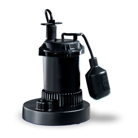
This discharge is threaded for 1½” pipe.
NOTE: DO NOT OVERTIGHTEN DISCHARGE
PIPE INTO PUMP PLASTIC DISCHARGE FITTING.
The pump can be installed with ABS, PVC or
polyethylene plastic pipe or galvanized pipe. Proper
adapters are required to connect plastic pipe to
pump.
A CHECK VALVE MUST BE USED IN THE
DISCHARGE LINE FOR ALL INSTALLATIONS.
Always install check valve with arrow on the body
in the direction of ow. A shut-off valve should also
be used.
AIR LOCKING
A sump pump is considered to be air locked if water
traps air in the pump and it cannot get out, thus
preventing pump from operating.
AS A PRECAUTION, IT IS RECOMMENDED THAT
A 1/8” HOLE BE DRILLED IN THE DISCHARGE
PIPE BELOW THE CHECK VALVE. THIS CHECK
VALVE SHOULD BE 12” TO 18” ABOVE PUMP
DISCHARGE. DO NOT PUT CHECK VALVE
DIRECTLY INTO PUMP DISCHARGE OPENING.
INSTALLING AND STARTING PUMP
1. These pumps have an integral ball float or
vertical float switch for automatic operation.
2. Refer to Typical Installation Drawing for
recommended installation. Install check valve
with arrow in direction of flow and drill 1/8” hole
in discharge pipe between pump and check
valve as noted.
3. After installation is complete plug cord into a 115
volt GROUNDED RECEPTACLE.
4. Run water into sump basin. Pump should turn
on at 9” to 10” water level. Allow pump to go
through several ON-OFF cycles to assure
satisfactory operation.
5. BE SURE BALL FLOAT SWITCH FLOATS
FREELY IN SUMP BASIN WITHOUT
TOUCHING BASIN WALLS. ADJUST PUMP
POSITION IN SUMP IF NECESSARY.
6. If a shut-off valve is used in discharge line, be
sure valve is open.
7. If pump does not operate properly, see
Troubleshooting Checklist for remedy.
MAINTENANCE AND SERVICE
If pump does not operate properly, follow steps
shown on Troubleshooting chart. If trouble cannot
be located with these steps shown, call Myers
service dealer, or take pump to Myers authorized
service center.
CAUTION: FOR ANY WORK ON PUMP OR
SWITCH, ALWAYS UNPLUG POWER CORD. DO
NOT JUST TURN OFF CIRCUIT BREAKER OR
UNSCREW FUSE.
CLEANING FLOAT
If pump becomes inoperative because of
accumulation of trash on the oat, remove pump
from sump and clean oat.
1. Wipe all water and dirt from pump and float.
2. If tar or paint have been put in the basin, it may
be necessary to thoroughly clean the float.
Kerosene can be used to remove tar or paint.
3. Be sure float operates freely after cleaning.
CLEANING IMPELLER AND
VOLUTE CASE
1. Remove three screws that hold plastic base and
volute. Remove four screws which hold volute
to motor housing. CAUTION: Warranty is void
if impeller or motor cap is removed.
2. Remove volute and clean impeller and volute
passage. If tar or paint has entered pump it
may be necessary to clean with kerosene.
CAUTION: Do not use strong paint solvents.
3. Be sure impeller turns freely after cleaning.
4. Clean out holes in plastic volute and wash
thoroughly before replacing.


