Pentax CA Instruction Manual

CA/4CA/MSV/MSH
MA/4MA/BMV/BMH
®

I – Italiano
DICHIARAZIONE DI INCORPORAZIONE
Si dichiara che i prodotti o quasimacchine in
elenco (models) sono conformi alle prescrizioni
delle direttive [D-CE] e costruiti nel rispetto
delle norme armonizzate [N-A] e che la doc-
umentazione tecnica pertinente è conforme
all’allegato VII B della Direttiva 2006/42/CE
UK – English
DECLARATION OF INCORPORATION
It is hereby declared that the products (mod-
els) in the list are compliant with the prescrip-
tions of Directives [D-CE] and built in compli-
ance with the harmonised regulations [N-A]
and that the pertaining technical documenta-
tion is compliant with attachment VII B of Di-
rective 2006/42/CE
D – Deutsch
EINBAUERKLÄRUNG
Es wird erklärt, dass die aufgeführten Produkte
oder die Teilmaschinen (Models) konform mit
den Vorschriften der Richtlinien [R- EG] sind
und dass sie gemäß den harmonisierten Nor-
men [H - N] hergestellt wurden und dass die
zugehörige technische Dokumentation kon-
form mit dem Anhang VII B der Richtlinie
2006/42/EG ist.
F – Français
DÉCLARATION D’INCORPORATION
Nous déclarons que les produits ou quasi-ma-
chines gurant dans la liste (models) sont con-
formes aux prescriptions des Directives [D-CE]
et sont fabriqués conformément aux normes
harmonisées [N-A]. En outre la documentation
technique spécique est conforme à la pièce
jointe VII B de la Directive 2006/42/CE.
S – Svenka
FÖRKLARAN OM INKORPORERING
Härmed förklaras att de angivna produkterna
eller delmaskinerna (models) överensstämmer
med föreskrifterna i direktivet [D-CE] och är
konstruerade med hänsyn till de harmonise-
rade normerna [N-A] och att den tillhörande
tekniska dokumentationen överensstämmer
med bilaga VII i direktivet 2006/45/CE
N – Norsk
ERKLÆRING FOR INNBYGGING
Erklærer at produktene eller delmaskinene på
listen (models) oppfyller kravene i direktivene
[D-CE] og at de er konstruerte i henhold til
de harmoniserte normene [N-A] og at den til-
hørende tekniske dokumentasjonen er i over-
ensstemmelse med vedlegg VII B i Direktivet
2006/42/EF.
D – Dansk
INKORPORERINGSERKLÆRING
Hermed erklæres at produkterne eller del-
maskinerne på listen (models) er konforme
med forskrifterne i direktiverne [D-CE] og
at de er fremstillet i overensstemmelse med
de harmoniserede standarder [N-A] samt at
den vedrørende tekniske dokumentation er i
overensstemmelse med bilag VII B i direktiv
2006/42/EF
NL – Nederland
INCORPORATIEVERKLARING
Hierbij verklaren wij dat de producten of deel-
machines uit de lijst (models) conform zijn
met de voorschriften van de richtlijnen [D-CE]
en gebouwd zijn in naleving van de geharmo-
niseerde normen [N-A] en dat de betreffende
technische documentatie conform is met bi-
jlage VII B van de Richtlijn 2006/42/CE
F – Suomi
LIITTÄMISVAKUUTUS
Vakuutamme, että luettelossa olevat koneet
tai puolivalmisteet (models) vastaavat direkti-
ivien [D-EY] asettamia vaatimuksia ja että ne
on valmistettu harmonisoitujen standardien
mukaisesti [H-S] ja että asiaan kuuluva te-
kninen dokumentaatio vastaa Euroopan neu-
voston direktiiviä 2006/42/EY liite VII B.
E– Español
DECLARACIÓN DE INCORPORACIÓN
Se declara que los productos o cuasi máquinas
que guran en la lista (models) son conformes
con lo establecido por las directivas [D-CE],
que han sido fabricados cumpliendo las nor-
mas armonizadas [N-A] y que la document-
ación técnica correspondiente es conforme con
el anexo VII B de la Directiva 2006/42/CE
P– Portoguês
DECLARAÇÃO DE INCORPORAÇÃO
Declara-se que os produtos ou quase-máqui-
nas na lista (models) estão em conformidade
com as prescrições das diretivas [D-CE], fab-
ricados no respeito das normas harmonizadas
[N-A] e que a documentação técnica pertinen-
te está em conformidade com o alegado VII B
da Diretiva 2006/42/CE.
EL – ΕΛΛΗΝΙΚΑ
ΔΗΛΩΣΗ ΕΝΣΩΜΑΤΩΣΗΣ
Δηλώνει ότι τα προϊόντα ή τα μηχανήματα
του καταλόγου (models) συνάδουν με τις
προδιαγραφές των οδηγιών [D-CE] και έχουν
κατασκευαστεί τηρώντας τους εναρμονισμένους
κανονισμούς [N-A] και την σχετική τεχνική
τεκμηρίωση και συμμορφώνονται με το
παράρτημα VII B της Οδηγίας 2006/42/CE
TR – Türkçe
ORTAKLIK BEYANI
Listedeki (models) ürün ve makinelerin, [D-
CE] direktieri yönergelerine uygun oldukları
ve ilgili harmonize [N-A] direktiere uyularak
imal edildikleri, ve ilgili teknik dokümantasy-
onun 2006/42/CE Direktinin VII B ekine uy-
gun olduğu beyan edilir.
Pag. 4
(D-CE)
98/37/CE; 2006/42/CE; 2000/14/CE (followed procedure: annex V).
(N-A)
EN ISO 12100; EN ISO 14121; EN ISO 3744;
EN 733 (main dimensions and rated performance) for models CA
/ 4CA
models:
CA / 4CA
Acoustic pressure level: <80 dB (A) – when installed following the
instructions indicated in this manual and according to the state of
the art rules.
Pump-motor sound emission: consider even the sound level de-
clared by the electric motor manufacturer.
MSV / MSH (hydraulic part)
Acoustic pressure level):< 90 dB(A) – when installed following the
instructions indicated in this manual and according to the state of
the art rules.
Pump-motor sound emission: consider even the sound level de-
clared by the electric motor manufacturer.
Manufacturer and depositary of tecnical documentation:
PENTAX S.p.A.
Viale dell’industria, 1
37040 Veronella (VR) - Italia
Gianluigi Pedrollo (President)
Veronella (Vr), 01/01/2011
Pag. 5

Pag. 6
ITALIANO
ENGLISH
DEUTSCH
FRANÇAIS
SVENSKA
NORSK
DANSK
NEDERLANDS
SUOMI
ESPANOL
PORTOGUES
TÜRKÇE
Pag. 8
Pag. 11
Pag. 14
Pag. 17
Pag. 20
Pag. 23
Pag. 26
Pag. 29
Pag. 32
Pag. 35
Pag. 38
Pag. 44
Pag. 41
I – Italiano
DICHIARAZIONE DI INCORPORAZIONE
Si dichiara che i prodotti o quasimacchine in
elenco (models) sono conformi alle prescrizioni
delle direttive [D-CE] e costruiti nel rispetto
delle norme armonizzate [N-A] e che la doc-
umentazione tecnica pertinente è conforme
all’allegato VII B della Direttiva 2006/42/CE
UK – English
DECLARATION OF INCORPORATION
It is hereby declared that the products (mod-
els) in the list are compliant with the prescrip-
tions of Directives [D-CE] and built in compli-
ance with the harmonised regulations [N-A]
and that the pertaining technical documenta-
tion is compliant with attachment VII B of Di-
rective 2006/42/CE
D – Deutsch
EINBAUERKLÄRUNG
Es wird erklärt, dass die aufgeführten Produkte
oder die Teilmaschinen (Models) konform mit
den Vorschriften der Richtlinien [R- EG] sind
und dass sie gemäß den harmonisierten Nor-
men [H - N] hergestellt wurden und dass die
zugehörige technische Dokumentation kon-
form mit dem Anhang VII B der Richtlinie
2006/42/EG ist.
F – Français
DÉCLARATION D’INCORPORATION
Nous déclarons que les produits ou quasi-ma-
chines gurant dans la liste (models) sont con-
formes aux prescriptions des Directives [D-CE]
et sont fabriqués conformément aux normes
harmonisées [N-A]. En outre la documentation
technique spécique est conforme à la pièce
jointe VII B de la Directive 2006/42/CE.
S – Svenka
FÖRKLARAN OM INKORPORERING
Härmed förklaras att de angivna produkterna
eller delmaskinerna (models) överensstämmer
med föreskrifterna i direktivet [D-CE] och är
konstruerade med hänsyn till de harmonise-
rade normerna [N-A] och att den tillhörande
tekniska dokumentationen överensstämmer
med bilaga VII i direktivet 2006/45/CE
N – Norsk
ERKLÆRING FOR INNBYGGING
Erklærer at produktene eller delmaskinene på
listen (models) oppfyller kravene i direktivene
[D-CE] og at de er konstruerte i henhold til
de harmoniserte normene [N-A] og at den til-
hørende tekniske dokumentasjonen er i over-
ensstemmelse med vedlegg VII B i Direktivet
2006/42/EF.
D – Dansk
INKORPORERINGSERKLÆRING
Hermed erklæres at produkterne eller del-
maskinerne på listen (models) er konforme
med forskrifterne i direktiverne [D-CE] og
at de er fremstillet i overensstemmelse med
de harmoniserede standarder [N-A] samt at
den vedrørende tekniske dokumentation er i
overensstemmelse med bilag VII B i direktiv
2006/42/EF
NL – Nederland
INCORPORATIEVERKLARING
Hierbij verklaren wij dat de producten of deel-
machines uit de lijst (models) conform zijn
met de voorschriften van de richtlijnen [D-CE]
en gebouwd zijn in naleving van de geharmo-
niseerde normen [N-A] en dat de betreffende
technische documentatie conform is met bi-
jlage VII B van de Richtlijn 2006/42/CE
F – Suomi
LIITTÄMISVAKUUTUS
Vakuutamme, että luettelossa olevat koneet
tai puolivalmisteet (models) vastaavat direkti-
ivien [D-EY] asettamia vaatimuksia ja että ne
on valmistettu harmonisoitujen standardien
mukaisesti [H-S] ja että asiaan kuuluva te-
kninen dokumentaatio vastaa Euroopan neu-
voston direktiiviä 2006/42/EY liite VII B.
E– Español
DECLARACIÓN DE INCORPORACIÓN
Se declara que los productos o cuasi máquinas
que guran en la lista (models) son conformes
con lo establecido por las directivas [D-CE],
que han sido fabricados cumpliendo las nor-
mas armonizadas [N-A] y que la document-
ación técnica correspondiente es conforme con
el anexo VII B de la Directiva 2006/42/CE
P– Portoguês
DECLARAÇÃO DE INCORPORAÇÃO
Declara-se que os produtos ou quase-máqui-
nas na lista (models) estão em conformidade
com as prescrições das diretivas [D-CE], fab-
ricados no respeito das normas harmonizadas
[N-A] e que a documentação técnica pertinen-
te está em conformidade com o alegado VII B
da Diretiva 2006/42/CE.
EL – ΕΛΛΗΝΙΚΑ
ΔΗΛΩΣΗ ΕΝΣΩΜΑΤΩΣΗΣ
Δηλώνει ότι τα προϊόντα ή τα μηχανήματα
του καταλόγου (models) συνάδουν με τις
προδιαγραφές των οδηγιών [D-CE] και έχουν
κατασκευαστεί τηρώντας τους εναρμονισμένους
κανονισμούς [N-A] και την σχετική τεχνική
τεκμηρίωση και συμμορφώνονται με το
παράρτημα VII B της Οδηγίας 2006/42/CE
TR – Türkçe
ORTAKLIK BEYANI
Listedeki (models) ürün ve makinelerin, [D-
CE] direktieri yönergelerine uygun oldukları
ve ilgili harmonize [N-A] direktiere uyularak
imal edildikleri, ve ilgili teknik dokümantasy-
onun 2006/42/CE Direktinin VII B ekine uy-
gun olduğu beyan edilir.
Pag. 4
ITALIANO
ENGLISH
DEUTSCH
FRANÇAIS
SVENSKA
NORSK
DANSK
NEDERLANDS
SUOMI
ESPANOL
PORTOGUES
TÜRKÇE
Pag. 8
Pag. 11
Pag. 14
Pag. 17
Pag. 20
Pag. 23
Pag. 26
Pag. 29
Pag. 32
Pag. 35
Pag. 38
Pag. 44
Pag. 41
ITALIANO
ENGLISH
DEUTSCH
FRANÇAIS
SVENSKA
NORSK
DANSK
NEDERLANDS
SUOMI
ESPANOL
PORTOGUES
TÜRKÇE
Pag. 8
Pag. 11
Pag. 14
Pag. 17
Pag. 20
Pag. 23
Pag. 26
Pag. 29
Pag. 32
Pag. 35
Pag. 38
Pag. 44
Pag. 41

Condizioni e limiti di impiego
Le pompe centrifughe mod. CA/4CA e elettropompe centrifughe multistadio mod. MSH e MSV PENTAX
Sono adatte per il pompaggio di acqua pulita e liquidi chimicamente e meccanicamente non aggres-
sivi per i materiali della pompa, non esplosivi o inammabili, non contenti sostanze solide o brose,
con temperature da -15°C no a +90 °C;
Tenere presente che un’elevata temperatura del liquido da pompare, la sua densità e viscosità,
così come l’altitudine del luogo di installazione, riducono la possibilità/capacità di aspirazione delle
pompe.
Devono essere installate in luoghi ben areati, non polverosi, protetti dalle intemperie, con tempe-
ratura ambiente compresa tra 5 e 40 °C, rigorosamente non in presenza di atmosfere esplosive.
Nell’installare la macchina, è consigliabile valutare attentamente lo spazio necessario per eventuali
riparazioni o rimozione della stessa. Da ricordare che la temperatura ambiente e l’altitudine del luogo
di installazione della pompa inuenzano la possibilità o meno di far funzionare il motore elettrico a
pieno carico: temperature ambiente eccessive e bassa densità dell’aria riducono infatti il raffredda-
mento del motore elettrico.
Sono previste con l’asse del rotore orizzontale (mod. CA/4CA e MSH) oppure verticale (mod. MSV) e
piedi/base di appoggio in basso; Per ragioni di sicurezza si consiglia di ssare la pompa utilizzando gli
appositi fori presenti sui piedi/base di appoggio.
Sono dotate di bocche angiate provviste di controangia lettata:
• modelli orizzontali (CA/4CA E MSH): aspirazione assiale e mandata radiale verso l’alto;
• modelli verticali (MSV): bocche sovrapposte o contrapposte con aspirazione nella parte inferiore
e mandata nella parte superiore.
Non possono essere soggette a più di:
• 30 avviamenti all’ora ad intervalli regolari: modelli con potenza nominale no a 2.2 kW;
• 15 avviamenti all’ora ad intervalli regolari: modelli con potenza nominale da 3 a 7.5 kW;
• 10 avviamenti all’ora ad intervalli regolari: modelli con potenza nominale da 10 a 37 kW;
la quantità massima tollerabile è tanto più bassa quanto maggiore è la potenza della macchina.
Gli avviamenti ripetuti sono meno gravosi per la pompa che non per il motore elettrico che vi è ac-
coppiato; si consiglia, pertanto - per le pompe mod. CA/4CA - di fare riferimento alla documentazione
fornita dal costruttore del motore stesso.
Possono sopportare una pressione massima di esercizio (uguale a pressione in aspirazione + preva-
lenza a valvola di mandata chiusa) pari a 10 bar per le pompe mod. CA/4CA e pari a 30 bar per le
pompe mod. MSV/H. Possono lavorare a servizio continuo e lavorare ad una velocità massima pari a
3600 giri/min (ad eccezione dei mod. CA65-315A, CA65-315-B, CA65-315C, CA65-315D per i quali
la velocità massima è di 1800 giri/min).
Installazione ed allineamento pompe CA/4CA
Istallazione e allineamento devono essere effettuati da personale esperto e qualicato.
Se la pompa verrà utilizzata per pompare acqua potabile, essa va preventivamente ed abbondantemente
lavata con acqua pulita onde rimuovere eventuali particelle estranee, grassi, residui di vernici e liquidi di
prova. Le pompe mod. CA/4CA sono previste per l’accoppiamento a motori elettrici standard in forma co-
struttiva IM B3 (IEC 34-7, IEC 72) tramite basamento e giunto elastico di collegamento/trascinamento. Il
basamento, su cui vengono ssate la pompa e la macchina motrice, deve essere opportunamente dimen-
sionato in funzione del peso del gruppo e delle sollecitazioni di funzionamento.
Sollevare e trasportare la pompa ed il gruppo pompa-motore come indicato in - Fig. 1 -.
Durante la movimentazione ci si deve assicurare che la pompa ed il gruppo completo si mantengano in po-
sizione orizzontale; non è ammissibile allacciare funi all’estremità libera della pompa o al golfare del motore
per movimentare l’intero gruppo. Porre attenzione alla movimentazione delle pompe perché, se compiuta
in maniera errata, essa può danneggiare le macchine e comprometterne la funzionalità. – Fig. 1 -
Per l’assemblaggio pompa-motore, eseguire le seguenti operazioni:
Pulire accuratamente le superci di accoppiamento;
Fissare la pompa sul basamento per mezzo degli appositi punti di ancoraggio e allentare le viti di ssaggio
del piede di sostengo della pompa stessa;
Posizionare la macchina motrice (motore) sul basamento;
Montare i due semigiunti, lato pompa e lato motore, sulle relative estremità d’albero;
Accoppiare le due macchine (pompa e motore) vericando che rimanga una luce pari a 3-4 mm tra le due
facce contrapposte dei semigiunti e degli alberi pompa e motore;
Con un comparatore o un calibro per spessori ed una riga, controllare l’allineamento (concentricità e paral-
lelismo) dei semigiunti e degli alberi pompa e motore; i controlli vanno eseguiti su 4 punti diametralmente
opposti - Fig. 2-3 -. Se necessario, recuperare eventuali disallineamenti aggiungendo o togliendo spessori
calibrati tra i piedi di appoggio delle macchine (pompa e motore) e basamento;
Completare il ssaggio del gruppo sul basamento montando la protezione dell’organo di trasmissione del
moto ed ogni altra eventuale protezione che si renda necessaria per soddisfare i requisiti di sicurezza.
Il gruppo pompa-motore, accoppiato su di un unico basamento in prolati, deve quindi essere ben ssato
alla soletta in calcestruzzo (opportunamente dimensionata in modo da poter sopportare tutte le solleci-
tazioni che derivano dal gruppo e dalle tubazioni). Il gruppo deve essere istallato su un piano livellato:
supportare la piastra di base con spessori posti in prossimità dei bulloni di ancoraggio (e in mezzeria, nel
caso di piastre di grosse dimensioni); controllare la “planarità” con l’ausilio di un livella a bolla collocata
sull’albero e sulla bocca di mandata della pompa. Lasciare tra piastra e fondazione uno spazio pari a circa
ISTRUZIONI PER L’INSTALLAZIONE E L’UTILIZZO DEL-
LE POMPE PENTAX MOD. CA/4CA ED ELETTROPOMPE
PENTAX MULTISTADIO PENTAX MOD. MSV/MSH
3
3
3
3
3
3
Pag. 8
30-40 mm per la colata di cemento liquido di ssaggio – Fig. 3 -.
Solo quando il cemento ha fatto presa, serrare uniformemente i bulloni di fondazione e rivericare il per-
fetto allineamento pompa-motore seguendo la procedura appena descritta.
L’allineamento deve essere rivericato quando il gruppo raggiunge la sua temperatura di funzionamento.
Finché le fondazioni sono nuove e l’impianto non è stato collaudato in tutte le condizioni di funzionamento,
l’allineamento deve essere rivericato ad intervalli regolari ed eventualmente corretto.
Un allineamento o un piazzamento imprecisi del gruppo oppure un difettoso collegamento delle tubazioni,
possono essere causa di vibrazioni e portare ad un aumento di rumorosità, ad una veloce usura dei tasselli
elastici dei semigiunti, ad un danneggiamento dei cuscinetti, della tenuta meccanica e delle parti interne.
Nel posizionamento del gruppo pompa-motore ricordarsi di lasciare dietro al motore uno spazio sufciente
per consentire una circolazione d’aria adeguata alle necessità di raffreddamento del motore stesso.
Installazione elettropompe MSV/MSH
Sollevare e trasportare la pompa e il gruppo pompa-motore imbracandoli in modo sicuro. Non utilizzare
eventuali golfari sul motore poiché gli stessi non sono dimensionati a sopportare il peso del gruppo com-
pleto – Fig. 1 -.
Gli aspetti di sicurezza in caso di acquisto della sola pompa e di accoppiamento con un motore diverso da
quanto previsto nel nostro catalogo, dovranno essere garantiti da chi esegue il collegamento.
Nel caso di gruppo pompa-motore fornito già assemblato e pronto per l’installazione, è sufciente ssare la
macchina, per mezzo dei fori di ancoraggio previsti (sulla base di aspirazione per macchine verticali mod.
MSV, sulle staffe di appoggio del corpo aspirante e della lanterna di collegamento pompa-motore nel caso
di macchine orizzontali mod. MSH) ad una soletta in calcestruzzo opportunamente dimensionata, in consi-
derazione del peso del gruppo e delle sollecitazioni di funzionamento.
Nel caso in cui il gruppo pompa-motore sia invece da assemblare, procedere eseguendo le seguenti ope-
razioni:
appoggiare la pompa sul basamento in posizione verticale, nel caso di gruppi mod. MSV, o orizzontale
nel caso di gruppi mod. MSH;
posizionare il motore elettrico e avvicinarlo alla pompa;
pulire accuratamente le superci di accoppiamento e togliere la rete di protezione del giunto di col-
legamento/trascinamento;
montare i due semigiunti, lato pompa e lato motore, sulle relative estremità d’albero;
accoppiare le due macchine (pompa e motore) e serrare a fondo le viti di accoppiamento dei due
semigiunti prestando attenzione che:
• ogni vite sia accompagnata da una rondella antisvitamento (tipo grower),
• nel serrare, ci sia un sollevamento della parte idraulica rotante (albero pompa e giranti);
completare il ssaggio del gruppo sul basamento montando la protezione dell’organo di trasmissione
del moto;
per non trasmettere sollecitazioni al gruppo, recuperare eventuali disallineamenti fra i punti di anco-
raggio del gruppo ed il piano di appoggio utilizzando opportuni spessori.
Nel posizionamento del gruppo pompa-motore, ricordarsi di lasciare dietro (nel caso di macchine orizzontali
mod. MSH) o sopra (nel caso di macchine verticali mod. MSV/HV) il motore, uno spazio sufciente per
consentire una circolazione d’aria adeguata alle necessità di raffreddamento del motore stesso.
N.B. I gruppi pompa-motore delle serie MSV e MSH sono previsti per l’accoppiamento, tramite giunto di
collegamento/trascinamento, a motori elettrici Pentax non-standard (sia per potenza/grandezza, sia per
sporgenza d’albero).
I valori di rumorosità riportati nel paragrafo precedente fanno riferimento a gruppi con motore Pentax.
Tubazioni
Le tubazioni devono essere ssate ed ancorate su propri appoggi e collegate in modo che non trasmettano
forze, tensioni e vibrazioni alla pompa; disporre correttamente gli eventuali compensatori (giunti essibili
di espansione) per assorbire dilatazioni o vibrazioni - Fig. 4-5-6 -.
Il diametro interno delle tubazioni dipende, oltre che dalla loro lunghezza, dalla portata da elaborare: esso
deve essere scelto in modo che la velocità del liquido non superi 1,4-1,5 m/s in aspirazione e 2,4-2,5 m/s
in mandata; in ogni caso le tubazioni devono avere un diametro non inferiore al diametro delle bocche
della pompa. La pompa va istallata quanto più vicino al punto di prelevamento del liquido (porre attenzione
all’NPSH e alle perdite di carico nelle tubazioni). Prima della loro installazione vericare che le tubazioni
siano internamente pulite.
La tubazione di aspirazione deve: - Fig. 5 -
• essere quanto più breve possibile, senza strozzature e brusche variazioni di direzione (usare giunti
conici se ci sono variazioni di diametro);
• essere a perfetta tenuta e resistere alla depressione che si crea all’aspirazione della pompa;
• avere un andamento ascendente verso la pompa, in modo da evitare sacche d’aria che potrebbero
impedire l’adescamento della pompa o causarne il disadescamento.
Per funzionamento della pompa in aspirazione inserire una valvola di fondo con succhieruola. Per un cor-
retto funzionamento della pompa, l’estremità del tubo di aspirazione deve essere immersa in acqua ad una
profondità di almeno due volte il diametro del tubo stesso. Per funzionamento sotto battente inserire una
valvola di intercettazione che, se a saracinesca, va montata con l’asse del volantino orizzontale. - Fig. 6 -.
La tubazione di mandata è opportuno sia munita di una valvola di ritegno e di una valvola di regola-
zione. La prima, posizionata a monte della seconda, protegge la pompa dal colpo d’ariete ed impedi-
sce il deusso invertito attraverso la girante, qualora si abbia un arresto improvviso della pompa. La
valvola di regolazione è invece usata per regolare portata, prevalenza e potenza assorbita. Installare
sulla tubazione di mandata un indicatore di pressione (manometro). - Fig. 4-5-6 -.
Dopo l’istallazione e prima della messa in marcia del gruppo (pompe mod. CA/4CA), vericare il serraggio
dei bulloni di fondazione, il collegamento delle tubazioni e ricontrollare l’allineamento del giunto (pompa-
3
3
3
3
3
3
3
3
3
Pag. 9
I – Italiano
DICHIARAZIONE DI INCORPORAZIONE
Si dichiara che i prodotti o quasimacchine in
elenco (models) sono conformi alle prescrizioni
delle direttive [D-CE] e costruiti nel rispetto
delle norme armonizzate [N-A] e che la doc-
umentazione tecnica pertinente è conforme
all’allegato VII B della Direttiva 2006/42/CE
UK – English
DECLARATION OF INCORPORATION
It is hereby declared that the products (mod-
els) in the list are compliant with the prescrip-
tions of Directives [D-CE] and built in compli-
ance with the harmonised regulations [N-A]
and that the pertaining technical documenta-
tion is compliant with attachment VII B of Di-
rective 2006/42/CE
D – Deutsch
EINBAUERKLÄRUNG
Es wird erklärt, dass die aufgeführten Produkte
oder die Teilmaschinen (Models) konform mit
den Vorschriften der Richtlinien [R- EG] sind
und dass sie gemäß den harmonisierten Nor-
men [H - N] hergestellt wurden und dass die
zugehörige technische Dokumentation kon-
form mit dem Anhang VII B der Richtlinie
2006/42/EG ist.
F – Français
DÉCLARATION D’INCORPORATION
Nous déclarons que les produits ou quasi-ma-
chines gurant dans la liste (models) sont con-
formes aux prescriptions des Directives [D-CE]
et sont fabriqués conformément aux normes
harmonisées [N-A]. En outre la documentation
technique spécique est conforme à la pièce
jointe VII B de la Directive 2006/42/CE.
S – Svenka
FÖRKLARAN OM INKORPORERING
Härmed förklaras att de angivna produkterna
eller delmaskinerna (models) överensstämmer
med föreskrifterna i direktivet [D-CE] och är
konstruerade med hänsyn till de harmonise-
rade normerna [N-A] och att den tillhörande
tekniska dokumentationen överensstämmer
med bilaga VII i direktivet 2006/45/CE
N – Norsk
ERKLÆRING FOR INNBYGGING
Erklærer at produktene eller delmaskinene på
listen (models) oppfyller kravene i direktivene
[D-CE] og at de er konstruerte i henhold til
de harmoniserte normene [N-A] og at den til-
hørende tekniske dokumentasjonen er i over-
ensstemmelse med vedlegg VII B i Direktivet
2006/42/EF.
D – Dansk
INKORPORERINGSERKLÆRING
Hermed erklæres at produkterne eller del-
maskinerne på listen (models) er konforme
med forskrifterne i direktiverne [D-CE] og
at de er fremstillet i overensstemmelse med
de harmoniserede standarder [N-A] samt at
den vedrørende tekniske dokumentation er i
overensstemmelse med bilag VII B i direktiv
2006/42/EF
NL – Nederland
INCORPORATIEVERKLARING
Hierbij verklaren wij dat de producten of deel-
machines uit de lijst (models) conform zijn
met de voorschriften van de richtlijnen [D-CE]
en gebouwd zijn in naleving van de geharmo-
niseerde normen [N-A] en dat de betreffende
technische documentatie conform is met bi-
jlage VII B van de Richtlijn 2006/42/CE
F – Suomi
LIITTÄMISVAKUUTUS
Vakuutamme, että luettelossa olevat koneet
tai puolivalmisteet (models) vastaavat direkti-
ivien [D-EY] asettamia vaatimuksia ja että ne
on valmistettu harmonisoitujen standardien
mukaisesti [H-S] ja että asiaan kuuluva te-
kninen dokumentaatio vastaa Euroopan neu-
voston direktiiviä 2006/42/EY liite VII B.
E– Español
DECLARACIÓN DE INCORPORACIÓN
Se declara que los productos o cuasi máquinas
que guran en la lista (models) son conformes
con lo establecido por las directivas [D-CE],
que han sido fabricados cumpliendo las nor-
mas armonizadas [N-A] y que la document-
ación técnica correspondiente es conforme con
el anexo VII B de la Directiva 2006/42/CE
P– Portoguês
DECLARAÇÃO DE INCORPORAÇÃO
Declara-se que os produtos ou quase-máqui-
nas na lista (models) estão em conformidade
com as prescrições das diretivas [D-CE], fab-
ricados no respeito das normas harmonizadas
[N-A] e que a documentação técnica pertinen-
te está em conformidade com o alegado VII B
da Diretiva 2006/42/CE.
EL – ΕΛΛΗΝΙΚΑ
ΔΗΛΩΣΗ ΕΝΣΩΜΑΤΩΣΗΣ
Δηλώνει ότι τα προϊόντα ή τα μηχανήματα
του καταλόγου (models) συνάδουν με τις
προδιαγραφές των οδηγιών [D-CE] και έχουν
κατασκευαστεί τηρώντας τους εναρμονισμένους
κανονισμούς [N-A] και την σχετική τεχνική
τεκμηρίωση και συμμορφώνονται με το
παράρτημα VII B της Οδηγίας 2006/42/CE
TR – Türkçe
ORTAKLIK BEYANI
Listedeki (models) ürün ve makinelerin, [D-
CE] direktieri yönergelerine uygun oldukları
ve ilgili harmonize [N-A] direktiere uyularak
imal edildikleri, ve ilgili teknik dokümantasy-
onun 2006/42/CE Direktinin VII B ekine uy-
gun olduğu beyan edilir.
Pag. 4
(D-CE)
98/37/CE; 2006/42/CE; 2000/14/CE (followed procedure: annex V).
(N-A)
EN ISO 12100; EN ISO 14121; EN ISO 3744;
EN 733 (main dimensions and rated performance) for models CA
/ 4CA
models:
CA / 4CA
Acoustic pressure level: <80 dB (A) – when installed following the
instructions indicated in this manual and according to the state of
the art rules.
Pump-motor sound emission: consider even the sound level de-
clared by the electric motor manufacturer.
MSV / MSH (hydraulic part)
Acoustic pressure level):< 90 dB(A) – when installed following the
instructions indicated in this manual and according to the state of
the art rules.
Pump-motor sound emission: consider even the sound level de-
clared by the electric motor manufacturer.
Manufacturer and depositary of tecnical documentation:
PENTAX S.p.A.
Viale dell’industria, 1
37040 Veronella (VR) - Italia
Gianluigi Pedrollo (President)
Veronella (Vr), 01/01/2011
Pag. 5

motore) seguendo la procedura descritta nel paragrafo precedente.
Collegamento elettrico pompe CA/4CA
I collegamenti elettrici devono essere eseguiti da personale qualicato nel rispetto delle disposizioni le-
gislative, delle norme tecniche locali vigenti e seguendo le istruzioni fornite dal costruttore del motore.
Si ricorda di eseguire sempre il collegamento a terra del gruppo pompa-motore; è necessaria, inoltre,
l’istallazione di un adeguata protezione elettrica (interruttore magnetotermico e interruttore differenziale
con soglia di intervento ≤ 30 mA) in grado di assicurare una disinserzione onnipolare dalla rete con una
distanza di apertura dei contatti di almeno 3 mm.
In ogni caso fare sempre riferimento a quanto specicato dal costruttore del motore elettrico.
Collegamento elettrico elettropompe MSV/MSH
Dimensionare opportunamente i cavi elettrici di alimentazione in base alla loro lunghezza e alla corrente
elettrica riportata sulla targa dell’elettropompa: preparare le estremità dei conduttori di alimentazione e di
terra, in maniera tale che in fase di connessione i conduttori stessi non possano sfuggire quando si serrano
i relativi dadi della morsettiera e la vite di terra. Il collegamento elettrico deve essere, in caso, eseguito da
un esperto, rispettando le locali normative di legge.
Vericare la corrispondenza tra tensione/frequenza della rete elettrica di alimentazione e i dati di targa
della elettropompa: collegare quindi i morsetti secondo le indicazioni dello schema riportato a pag. 4 e/o
posto all’interno del coperchio della morsettiera. Eseguire il collegamento a terra della elettropompa, utiliz-
zando l’apposito morsetto. Accertarsi che la rete elettrica di alimentazione abbia un efciente impianto di
terra e che quindi sia effettiva la messa a terra dell’elettropompa.
È sempre necessaria l’installazione di un’adeguata protezione elettrica (interruttore magnetotermico e
interruttore differenziale con soglia di intervento ≤ 30 mA) in grado di assicurare una disinserzione onni-
polare dalla rete con una distanza di apertura dei contatti di almeno 3 mm.
Avviamento
Prima di avviare la pompa vericare, a mano, che l’albero del motore giri liberamente. Avviare la pompa
solo dopo aver riempito completamente di liquido, attraverso l’apposito foro, il corpo pompa e la tubazione
di aspirazione - Fig. 7 -; è assolutamente da evitare il funzionamento a secco. Allo stesso modo è da evi-
tare, per periodi di tempo eccessivi (≥ 2-3 minuti), il funzionamento della macchina con bocca di mandata
completamente chiusa: ciò, provocando un surriscaldamento del liquido pompato, potrebbe causare un
danneggiamento della macchina o di alcuni suoi componenti. Si consiglia inoltre di assicurare una portata
minima uguale o maggiore almeno al 10% della portata nominale della pompa.
Nel caso la macchina funzionasse senza afusso d’acqua in aspirazione, il liquido presente nel corpo pom-
pa potrebbe surriscaldarsi: fare attenzione prima di qualsiasi intervento sulla macchina stessa (spurgo,
rabbocco, ecc.).
Tutte le elettropompe, devono avere rotazione oraria osservando il motore dal lato ventola. Nel caso di
elettropompe trifasi vericare la correttezza del senso di rotazione ed eventualmente invertire tra loro i cavi
elettrici di alimentazione di due fasi.
Per l’avviamento chiudere completamente la saracinesca di mandata, quindi, una volta messo in funzione
il gruppo di pompaggio, aprire lentamente la saracinesca regolando il punto di funzionamento entro i limiti
indicati sulla targa della pompa. Vericare inoltre che la corrente assorbita dal motore elettrico non sia
superiore a quella di targa. Controllare che la pompa lavori nel suo campo di prestazioni nominali indicato
sulla targa; in caso contrario regolare opportunamente la saracinesca posta sulla tubazione di mandata e/o
le pressioni di intervento di eventuali pressostati.
Manutenzione
Le pompe non necessitano di particolari manutenzioni, per il motore vedere eventuali istruzioni fornite dal
relativo costruttore. Se esiste il pericolo di congelamento del uido da pompare, in caso di arresto prolun-
gato della pompa, si consiglia di svuotare completamente il corpo pompa e le tubazioni. - Fig. 7 - Prima
di rimettere in marcia la pompa controllare che l’albero non sia bloccato da incrostazioni o altre cause e
riempire completamente di liquido il corpo pompa e la tubazione di aspirazione.
In caso di interventi sulla macchina, chiudere le saracinesche poste sulle tubazioni di aspirazione e manda-
ta e scaricare, mediante gli appositi fori sul corpo pompa, il liquido presente nella pompa: fare attenzione
alle caratteristiche del liquido pompato (temperatura e pressione).
N.B. Prima di qualsiasi intervento di manutenzione e/o riparazione staccare
l’alimentazione elettrica.
Messa fuori servizio
Questa tipologia di prodotto non necessita di procedure particolari per la messa fuori servizio o per lo
smantellamento. Si rimanda pertanto all’osservanza delle locali disposizioni di legge in fatto di smaltimen-
to, recupero, reimpiego, riciclaggio dei materiali.
Pag. 10
Conditions for using and installing the pumps
Centrifugual pumps models CA/4CA and multi-phase centrifugal motorised pumps, models MSH and MSV
PENTAX
Are used for pumping clean water and other liquids that are not chemically or mechanically harmful
for the pump materials, that are not explosive or ammable, not containing solid and brous sub-
stances, with a temperature from -15°C to +90 °C;
It should be remembered that high temperature in the pumped liquid, its density and viscosity, like
the altitude of the installation location for the motorised pump, reduce the intake capacity of the
pump.
They must be installed in a well-ventilated place, dust free, protected from the weather, with an
ambient temperature between 5 and 40°C, and never in explosive atmospheres. When the machine
is installed, it is advisable to leave sufcient space around it for any repair work or dismantling. It
should be remembered that the ambient temperature and altitude of the installation location effect
the possibility of the electric motor working at full charge; excessive ambient temperature and low
air density in fact reduce the cooling capacity of the electric motor.
They are provided with the rotor axle horizontal (mod. CA/4CA and MSH) or vertical (mod. MSV) and
feet/base at the bottom; for safety reasons it is advisable to anchor the autoclaves using the holes
in the supporting foot/base.
They have anged openings with threaded counter-anges:
• Horizontal models (CA/4CA and MSH): axial aspiration and radial delivery upwards;
• Vertical models (MSV): overlapped or counterposed openings with aspiration at the bottom and
delivery at the top.
They must not be subjected to:
• more than 30 start-ups per hour at regular intervals: models with rated output up to 2.2 kW;
• more than 15 start-ups per hour at regular intervals: models with rated output from 3 to 7.5 kW;
• more than 10 start-ups per hour at regular intervals: models with rated output from 10 to 37 kW;
The greater the power given off by the machine the lower the number of starts.
Repeated ignitions are less harmful for the pump than the electric motor installed; therefore it is
advisable – for the CA/4CA pumps – to always refer to the technical documentation supplied with
the motor.
The pumps can support a maximum working pressure (equal inlet pressure + closed delivery valve
head) of 10 bar for CA/4CA pumps and 30 bar for the MSV/H pumps. they can operate continuously
and at a maximum operating speed of 3600 min-1 (except for models CA65-315A, CA65-315B,
CA65-315C, CA65-315D for which the maximum speed is 1800 min-1.
Installation and alignment of pumps CA/4CA
Only expert qualied personnel must install and align the pumps.
If the pump is used to pump drinking water, it must be washed thoroughly with clean water beforehand to
remove all traces of foreign bodies, grease, residual paint and test uids. The mod. CA/4CA pumps can also
be coupled to standard electric motors with the IM B3 construction form (IEC 34-7, IEC 72) using a bedpla-
te and a connection/driving exible coupling. The bedplate, on which the pump and driving machine are
mounted, must have suitable dimensions for the weight of the unit and the operational stress and strain.
Lift and transport the pump and the pump-motor unit as indicated in - Fig 1 -.
During handling, make sure that the pump and the unit are always kept horizontally; ropes or cables must
not be put under the free end of the pump or in the eyebolt on the motor to move the entire assembly. Pay
special attention when moving the pump, because if it is not moved correctly it could damage the machine
and affect correct functions. – Fig. 1 -
To assemble the motor-pump, carry out the following operations:
Carefully clean the coupling surfaces;
Fit the pump to the bedplate using the appropriate anchor points and loosen the fastening screws of the
bearing bolts of the pump support;
Position the driving machine (motor) on the bedplate;
Fit and assemble the two parts of the coupling, pump side and motor side, on the corresponding ends of
the shaft;
Join the two machines (pump and motor) while checking that there is a clearance gap of 3-4 mm between
the opposed surfaces of the two halves of the coupling and the pump and motor shafts;
With a comparator or feeler gauge and a ruler, check the alignment (concentricity and parallelism) of the
coupling parts and the pump and motor shafts; check at the 4 diametrically opposite points - Fig. 2-3
-. If necessary, correct any misalignments by adding or removing calibrated shims between the machine
support feet (pump and motor) and bedplate;
Complete the operation of fastening the unit to the bedplate by assembling the movement transmission
unit, and any other protection that may be necessary to satisfy safety requirements.
The pump-motor unit, coupled on a single bedplate of structural steel, must then be xed properly to the
concrete slab (suitably dimensioned to bear all the stress and strain deriving from the unit and pipes). The
unit must be installed on level ground: support the bedplate with shims placed near the anchor bolts (and
in the middle for very large bedplates); level off with a spirit level placed on the shaft and on the pump
delivery outlet. Between the plate and the foundation leave a space of about 30-40 mm to pour the xing
liquid cement (Figure 3).
Only when the cement is hard, tighten the foundation bolts uniformly and check that the pump and motor
INSTRUCTIONS FOR INSTALLING AND OPERATING
PENTAX MOD. CA/4CA PUMPS AND PENTAX MULTI-
PHASE MOTORISED PUMPS MOD. MSV/MSH
3
3
3
3
3
3
Pag. 11
I – Italiano
DICHIARAZIONE DI INCORPORAZIONE
Si dichiara che i prodotti o quasimacchine in
elenco (models) sono conformi alle prescrizioni
delle direttive [D-CE] e costruiti nel rispetto
delle norme armonizzate [N-A] e che la doc-
umentazione tecnica pertinente è conforme
all’allegato VII B della Direttiva 2006/42/CE
UK – English
DECLARATION OF INCORPORATION
It is hereby declared that the products (mod-
els) in the list are compliant with the prescrip-
tions of Directives [D-CE] and built in compli-
ance with the harmonised regulations [N-A]
and that the pertaining technical documenta-
tion is compliant with attachment VII B of Di-
rective 2006/42/CE
D – Deutsch
EINBAUERKLÄRUNG
Es wird erklärt, dass die aufgeführten Produkte
oder die Teilmaschinen (Models) konform mit
den Vorschriften der Richtlinien [R- EG] sind
und dass sie gemäß den harmonisierten Nor-
men [H - N] hergestellt wurden und dass die
zugehörige technische Dokumentation kon-
form mit dem Anhang VII B der Richtlinie
2006/42/EG ist.
F – Français
DÉCLARATION D’INCORPORATION
Nous déclarons que les produits ou quasi-ma-
chines gurant dans la liste (models) sont con-
formes aux prescriptions des Directives [D-CE]
et sont fabriqués conformément aux normes
harmonisées [N-A]. En outre la documentation
technique spécique est conforme à la pièce
jointe VII B de la Directive 2006/42/CE.
S – Svenka
FÖRKLARAN OM INKORPORERING
Härmed förklaras att de angivna produkterna
eller delmaskinerna (models) överensstämmer
med föreskrifterna i direktivet [D-CE] och är
konstruerade med hänsyn till de harmonise-
rade normerna [N-A] och att den tillhörande
tekniska dokumentationen överensstämmer
med bilaga VII i direktivet 2006/45/CE
N – Norsk
ERKLÆRING FOR INNBYGGING
Erklærer at produktene eller delmaskinene på
listen (models) oppfyller kravene i direktivene
[D-CE] og at de er konstruerte i henhold til
de harmoniserte normene [N-A] og at den til-
hørende tekniske dokumentasjonen er i over-
ensstemmelse med vedlegg VII B i Direktivet
2006/42/EF.
D – Dansk
INKORPORERINGSERKLÆRING
Hermed erklæres at produkterne eller del-
maskinerne på listen (models) er konforme
med forskrifterne i direktiverne [D-CE] og
at de er fremstillet i overensstemmelse med
de harmoniserede standarder [N-A] samt at
den vedrørende tekniske dokumentation er i
overensstemmelse med bilag VII B i direktiv
2006/42/EF
NL – Nederland
INCORPORATIEVERKLARING
Hierbij verklaren wij dat de producten of deel-
machines uit de lijst (models) conform zijn
met de voorschriften van de richtlijnen [D-CE]
en gebouwd zijn in naleving van de geharmo-
niseerde normen [N-A] en dat de betreffende
technische documentatie conform is met bi-
jlage VII B van de Richtlijn 2006/42/CE
F – Suomi
LIITTÄMISVAKUUTUS
Vakuutamme, että luettelossa olevat koneet
tai puolivalmisteet (models) vastaavat direkti-
ivien [D-EY] asettamia vaatimuksia ja että ne
on valmistettu harmonisoitujen standardien
mukaisesti [H-S] ja että asiaan kuuluva te-
kninen dokumentaatio vastaa Euroopan neu-
voston direktiiviä 2006/42/EY liite VII B.
E– Español
DECLARACIÓN DE INCORPORACIÓN
Se declara que los productos o cuasi máquinas
que guran en la lista (models) son conformes
con lo establecido por las directivas [D-CE],
que han sido fabricados cumpliendo las nor-
mas armonizadas [N-A] y que la document-
ación técnica correspondiente es conforme con
el anexo VII B de la Directiva 2006/42/CE
P– Portoguês
DECLARAÇÃO DE INCORPORAÇÃO
Declara-se que os produtos ou quase-máqui-
nas na lista (models) estão em conformidade
com as prescrições das diretivas [D-CE], fab-
ricados no respeito das normas harmonizadas
[N-A] e que a documentação técnica pertinen-
te está em conformidade com o alegado VII B
da Diretiva 2006/42/CE.
EL – ΕΛΛΗΝΙΚΑ
ΔΗΛΩΣΗ ΕΝΣΩΜΑΤΩΣΗΣ
Δηλώνει ότι τα προϊόντα ή τα μηχανήματα
του καταλόγου (models) συνάδουν με τις
προδιαγραφές των οδηγιών [D-CE] και έχουν
κατασκευαστεί τηρώντας τους εναρμονισμένους
κανονισμούς [N-A] και την σχετική τεχνική
τεκμηρίωση και συμμορφώνονται με το
παράρτημα VII B της Οδηγίας 2006/42/CE
TR – Türkçe
ORTAKLIK BEYANI
Listedeki (models) ürün ve makinelerin, [D-
CE] direktieri yönergelerine uygun oldukları
ve ilgili harmonize [N-A] direktiere uyularak
imal edildikleri, ve ilgili teknik dokümantasy-
onun 2006/42/CE Direktinin VII B ekine uy-
gun olduğu beyan edilir.
Pag. 4
(D-CE)
98/37/CE; 2006/42/CE; 2000/14/CE (followed procedure: annex V).
(N-A)
EN ISO 12100; EN ISO 14121; EN ISO 3744;
EN 733 (main dimensions and rated performance) for models CA
/ 4CA
models:
CA / 4CA
Acoustic pressure level: <80 dB (A) – when installed following the
instructions indicated in this manual and according to the state of
the art rules.
Pump-motor sound emission: consider even the sound level de-
clared by the electric motor manufacturer.
MSV / MSH (hydraulic part)
Acoustic pressure level):< 90 dB(A) – when installed following the
instructions indicated in this manual and according to the state of
the art rules.
Pump-motor sound emission: consider even the sound level de-
clared by the electric motor manufacturer.
Manufacturer and depositary of tecnical documentation:
PENTAX S.p.A.
Viale dell’industria, 1
37040 Veronella (VR) - Italia
Gianluigi Pedrollo (President)
Veronella (Vr), 01/01/2011
Pag. 5
motore) seguendo la procedura descritta nel paragrafo precedente.
Collegamento elettrico pompe CA/4CA
I collegamenti elettrici devono essere eseguiti da personale qualicato nel rispetto delle disposizioni le-
gislative, delle norme tecniche locali vigenti e seguendo le istruzioni fornite dal costruttore del motore.
Si ricorda di eseguire sempre il collegamento a terra del gruppo pompa-motore; è necessaria, inoltre,
l’istallazione di un adeguata protezione elettrica (interruttore magnetotermico e interruttore differenziale
con soglia di intervento ≤ 30 mA) in grado di assicurare una disinserzione onnipolare dalla rete con una
distanza di apertura dei contatti di almeno 3 mm.
In ogni caso fare sempre riferimento a quanto specicato dal costruttore del motore elettrico.
Collegamento elettrico elettropompe MSV/MSH
Dimensionare opportunamente i cavi elettrici di alimentazione in base alla loro lunghezza e alla corrente
elettrica riportata sulla targa dell’elettropompa: preparare le estremità dei conduttori di alimentazione e di
terra, in maniera tale che in fase di connessione i conduttori stessi non possano sfuggire quando si serrano
i relativi dadi della morsettiera e la vite di terra. Il collegamento elettrico deve essere, in caso, eseguito da
un esperto, rispettando le locali normative di legge.
Vericare la corrispondenza tra tensione/frequenza della rete elettrica di alimentazione e i dati di targa
della elettropompa: collegare quindi i morsetti secondo le indicazioni dello schema riportato a pag. 4 e/o
posto all’interno del coperchio della morsettiera. Eseguire il collegamento a terra della elettropompa, utiliz-
zando l’apposito morsetto. Accertarsi che la rete elettrica di alimentazione abbia un efciente impianto di
terra e che quindi sia effettiva la messa a terra dell’elettropompa.
È sempre necessaria l’installazione di un’adeguata protezione elettrica (interruttore magnetotermico e
interruttore differenziale con soglia di intervento ≤ 30 mA) in grado di assicurare una disinserzione onni-
polare dalla rete con una distanza di apertura dei contatti di almeno 3 mm.
Avviamento
Prima di avviare la pompa vericare, a mano, che l’albero del motore giri liberamente. Avviare la pompa
solo dopo aver riempito completamente di liquido, attraverso l’apposito foro, il corpo pompa e la tubazione
di aspirazione - Fig. 7 -; è assolutamente da evitare il funzionamento a secco. Allo stesso modo è da evi-
tare, per periodi di tempo eccessivi (≥ 2-3 minuti), il funzionamento della macchina con bocca di mandata
completamente chiusa: ciò, provocando un surriscaldamento del liquido pompato, potrebbe causare un
danneggiamento della macchina o di alcuni suoi componenti. Si consiglia inoltre di assicurare una portata
minima uguale o maggiore almeno al 10% della portata nominale della pompa.
Nel caso la macchina funzionasse senza afusso d’acqua in aspirazione, il liquido presente nel corpo pom-
pa potrebbe surriscaldarsi: fare attenzione prima di qualsiasi intervento sulla macchina stessa (spurgo,
rabbocco, ecc.).
Tutte le elettropompe, devono avere rotazione oraria osservando il motore dal lato ventola. Nel caso di
elettropompe trifasi vericare la correttezza del senso di rotazione ed eventualmente invertire tra loro i cavi
elettrici di alimentazione di due fasi.
Per l’avviamento chiudere completamente la saracinesca di mandata, quindi, una volta messo in funzione
il gruppo di pompaggio, aprire lentamente la saracinesca regolando il punto di funzionamento entro i limiti
indicati sulla targa della pompa. Vericare inoltre che la corrente assorbita dal motore elettrico non sia
superiore a quella di targa. Controllare che la pompa lavori nel suo campo di prestazioni nominali indicato
sulla targa; in caso contrario regolare opportunamente la saracinesca posta sulla tubazione di mandata e/o
le pressioni di intervento di eventuali pressostati.
Manutenzione
Le pompe non necessitano di particolari manutenzioni, per il motore vedere eventuali istruzioni fornite dal
relativo costruttore. Se esiste il pericolo di congelamento del uido da pompare, in caso di arresto prolun-
gato della pompa, si consiglia di svuotare completamente il corpo pompa e le tubazioni. - Fig. 7 - Prima
di rimettere in marcia la pompa controllare che l’albero non sia bloccato da incrostazioni o altre cause e
riempire completamente di liquido il corpo pompa e la tubazione di aspirazione.
In caso di interventi sulla macchina, chiudere le saracinesche poste sulle tubazioni di aspirazione e manda-
ta e scaricare, mediante gli appositi fori sul corpo pompa, il liquido presente nella pompa: fare attenzione
alle caratteristiche del liquido pompato (temperatura e pressione).
N.B. Prima di qualsiasi intervento di manutenzione e/o riparazione staccare
l’alimentazione elettrica.
Messa fuori servizio
Questa tipologia di prodotto non necessita di procedure particolari per la messa fuori servizio o per lo
smantellamento. Si rimanda pertanto all’osservanza delle locali disposizioni di legge in fatto di smaltimen-
to, recupero, reimpiego, riciclaggio dei materiali.
Pag. 10
Conditions for using and installing the pumps
Centrifugual pumps models CA/4CA and multi-phase centrifugal motorised pumps, models MSH and MSV
PENTAX
Are used for pumping clean water and other liquids that are not chemically or mechanically harmful
for the pump materials, that are not explosive or ammable, not containing solid and brous sub-
stances, with a temperature from -15°C to +90 °C;
It should be remembered that high temperature in the pumped liquid, its density and viscosity, like
the altitude of the installation location for the motorised pump, reduce the intake capacity of the
pump.
They must be installed in a well-ventilated place, dust free, protected from the weather, with an
ambient temperature between 5 and 40°C, and never in explosive atmospheres. When the machine
is installed, it is advisable to leave sufcient space around it for any repair work or dismantling. It
should be remembered that the ambient temperature and altitude of the installation location effect
the possibility of the electric motor working at full charge; excessive ambient temperature and low
air density in fact reduce the cooling capacity of the electric motor.
They are provided with the rotor axle horizontal (mod. CA/4CA and MSH) or vertical (mod. MSV) and
feet/base at the bottom; for safety reasons it is advisable to anchor the autoclaves using the holes
in the supporting foot/base.
They have anged openings with threaded counter-anges:
• Horizontal models (CA/4CA and MSH): axial aspiration and radial delivery upwards;
• Vertical models (MSV): overlapped or counterposed openings with aspiration at the bottom and
delivery at the top.
They must not be subjected to:
• more than 30 start-ups per hour at regular intervals: models with rated output up to 2.2 kW;
• more than 15 start-ups per hour at regular intervals: models with rated output from 3 to 7.5 kW;
• more than 10 start-ups per hour at regular intervals: models with rated output from 10 to 37 kW;
The greater the power given off by the machine the lower the number of starts.
Repeated ignitions are less harmful for the pump than the electric motor installed; therefore it is
advisable – for the CA/4CA pumps – to always refer to the technical documentation supplied with
the motor.
The pumps can support a maximum working pressure (equal inlet pressure + closed delivery valve
head) of 10 bar for CA/4CA pumps and 30 bar for the MSV/H pumps. they can operate continuously
and at a maximum operating speed of 3600 min-1 (except for models CA65-315A, CA65-315B,
CA65-315C, CA65-315D for which the maximum speed is 1800 min-1.
Installation and alignment of pumps CA/4CA
Only expert qualied personnel must install and align the pumps.
If the pump is used to pump drinking water, it must be washed thoroughly with clean water beforehand to
remove all traces of foreign bodies, grease, residual paint and test uids. The mod. CA/4CA pumps can also
be coupled to standard electric motors with the IM B3 construction form (IEC 34-7, IEC 72) using a bedpla-
te and a connection/driving exible coupling. The bedplate, on which the pump and driving machine are
mounted, must have suitable dimensions for the weight of the unit and the operational stress and strain.
Lift and transport the pump and the pump-motor unit as indicated in - Fig 1 -.
During handling, make sure that the pump and the unit are always kept horizontally; ropes or cables must
not be put under the free end of the pump or in the eyebolt on the motor to move the entire assembly. Pay
special attention when moving the pump, because if it is not moved correctly it could damage the machine
and affect correct functions. – Fig. 1 -
To assemble the motor-pump, carry out the following operations:
Carefully clean the coupling surfaces;
Fit the pump to the bedplate using the appropriate anchor points and loosen the fastening screws of the
bearing bolts of the pump support;
Position the driving machine (motor) on the bedplate;
Fit and assemble the two parts of the coupling, pump side and motor side, on the corresponding ends of
the shaft;
Join the two machines (pump and motor) while checking that there is a clearance gap of 3-4 mm between
the opposed surfaces of the two halves of the coupling and the pump and motor shafts;
With a comparator or feeler gauge and a ruler, check the alignment (concentricity and parallelism) of the
coupling parts and the pump and motor shafts; check at the 4 diametrically opposite points - Fig. 2-3
-. If necessary, correct any misalignments by adding or removing calibrated shims between the machine
support feet (pump and motor) and bedplate;
Complete the operation of fastening the unit to the bedplate by assembling the movement transmission
unit, and any other protection that may be necessary to satisfy safety requirements.
The pump-motor unit, coupled on a single bedplate of structural steel, must then be xed properly to the
concrete slab (suitably dimensioned to bear all the stress and strain deriving from the unit and pipes). The
unit must be installed on level ground: support the bedplate with shims placed near the anchor bolts (and
in the middle for very large bedplates); level off with a spirit level placed on the shaft and on the pump
delivery outlet. Between the plate and the foundation leave a space of about 30-40 mm to pour the xing
liquid cement (Figure 3).
Only when the cement is hard, tighten the foundation bolts uniformly and check that the pump and motor
INSTRUCTIONS FOR INSTALLING AND OPERATING
PENTAX MOD. CA/4CA PUMPS AND PENTAX MULTI-
PHASE MOTORISED PUMPS MOD. MSV/MSH
3
3
3
3
3
3
Pag. 11
I – Italiano
DICHIARAZIONE DI INCORPORAZIONE
Si dichiara che i prodotti o quasimacchine in
elenco (models) sono conformi alle prescrizioni
delle direttive [D-CE] e costruiti nel rispetto
delle norme armonizzate [N-A] e che la doc-
umentazione tecnica pertinente è conforme
all’allegato VII B della Direttiva 2006/42/CE
UK – English
DECLARATION OF INCORPORATION
It is hereby declared that the products (mod-
els) in the list are compliant with the prescrip-
tions of Directives [D-CE] and built in compli-
ance with the harmonised regulations [N-A]
and that the pertaining technical documenta-
tion is compliant with attachment VII B of Di-
rective 2006/42/CE
D – Deutsch
EINBAUERKLÄRUNG
Es wird erklärt, dass die aufgeführten Produkte
oder die Teilmaschinen (Models) konform mit
den Vorschriften der Richtlinien [R- EG] sind
und dass sie gemäß den harmonisierten Nor-
men [H - N] hergestellt wurden und dass die
zugehörige technische Dokumentation kon-
form mit dem Anhang VII B der Richtlinie
2006/42/EG ist.
F – Français
DÉCLARATION D’INCORPORATION
Nous déclarons que les produits ou quasi-ma-
chines gurant dans la liste (models) sont con-
formes aux prescriptions des Directives [D-CE]
et sont fabriqués conformément aux normes
harmonisées [N-A]. En outre la documentation
technique spécique est conforme à la pièce
jointe VII B de la Directive 2006/42/CE.
S – Svenka
FÖRKLARAN OM INKORPORERING
Härmed förklaras att de angivna produkterna
eller delmaskinerna (models) överensstämmer
med föreskrifterna i direktivet [D-CE] och är
konstruerade med hänsyn till de harmonise-
rade normerna [N-A] och att den tillhörande
tekniska dokumentationen överensstämmer
med bilaga VII i direktivet 2006/45/CE
N – Norsk
ERKLÆRING FOR INNBYGGING
Erklærer at produktene eller delmaskinene på
listen (models) oppfyller kravene i direktivene
[D-CE] og at de er konstruerte i henhold til
de harmoniserte normene [N-A] og at den til-
hørende tekniske dokumentasjonen er i over-
ensstemmelse med vedlegg VII B i Direktivet
2006/42/EF.
D – Dansk
INKORPORERINGSERKLÆRING
Hermed erklæres at produkterne eller del-
maskinerne på listen (models) er konforme
med forskrifterne i direktiverne [D-CE] og
at de er fremstillet i overensstemmelse med
de harmoniserede standarder [N-A] samt at
den vedrørende tekniske dokumentation er i
overensstemmelse med bilag VII B i direktiv
2006/42/EF
NL – Nederland
INCORPORATIEVERKLARING
Hierbij verklaren wij dat de producten of deel-
machines uit de lijst (models) conform zijn
met de voorschriften van de richtlijnen [D-CE]
en gebouwd zijn in naleving van de geharmo-
niseerde normen [N-A] en dat de betreffende
technische documentatie conform is met bi-
jlage VII B van de Richtlijn 2006/42/CE
F – Suomi
LIITTÄMISVAKUUTUS
Vakuutamme, että luettelossa olevat koneet
tai puolivalmisteet (models) vastaavat direkti-
ivien [D-EY] asettamia vaatimuksia ja että ne
on valmistettu harmonisoitujen standardien
mukaisesti [H-S] ja että asiaan kuuluva te-
kninen dokumentaatio vastaa Euroopan neu-
voston direktiiviä 2006/42/EY liite VII B.
E– Español
DECLARACIÓN DE INCORPORACIÓN
Se declara que los productos o cuasi máquinas
que guran en la lista (models) son conformes
con lo establecido por las directivas [D-CE],
que han sido fabricados cumpliendo las nor-
mas armonizadas [N-A] y que la document-
ación técnica correspondiente es conforme con
el anexo VII B de la Directiva 2006/42/CE
P– Portoguês
DECLARAÇÃO DE INCORPORAÇÃO
Declara-se que os produtos ou quase-máqui-
nas na lista (models) estão em conformidade
com as prescrições das diretivas [D-CE], fab-
ricados no respeito das normas harmonizadas
[N-A] e que a documentação técnica pertinen-
te está em conformidade com o alegado VII B
da Diretiva 2006/42/CE.
EL – ΕΛΛΗΝΙΚΑ
ΔΗΛΩΣΗ ΕΝΣΩΜΑΤΩΣΗΣ
Δηλώνει ότι τα προϊόντα ή τα μηχανήματα
του καταλόγου (models) συνάδουν με τις
προδιαγραφές των οδηγιών [D-CE] και έχουν
κατασκευαστεί τηρώντας τους εναρμονισμένους
κανονισμούς [N-A] και την σχετική τεχνική
τεκμηρίωση και συμμορφώνονται με το
παράρτημα VII B της Οδηγίας 2006/42/CE
TR – Türkçe
ORTAKLIK BEYANI
Listedeki (models) ürün ve makinelerin, [D-
CE] direktieri yönergelerine uygun oldukları
ve ilgili harmonize [N-A] direktiere uyularak
imal edildikleri, ve ilgili teknik dokümantasy-
onun 2006/42/CE Direktinin VII B ekine uy-
gun olduğu beyan edilir.
Pag. 4
(D-CE)
98/37/CE; 2006/42/CE; 2000/14/CE (followed procedure: annex V).
(N-A)
EN ISO 12100; EN ISO 14121; EN ISO 3744;
EN 733 (main dimensions and rated performance) for models CA
/ 4CA
models:
CA / 4CA
Acoustic pressure level: <80 dB (A) – when installed following the
instructions indicated in this manual and according to the state of
the art rules.
Pump-motor sound emission: consider even the sound level de-
clared by the electric motor manufacturer.
MSV / MSH (hydraulic part)
Acoustic pressure level):< 90 dB(A) – when installed following the
instructions indicated in this manual and according to the state of
the art rules.
Pump-motor sound emission: consider even the sound level de-
clared by the electric motor manufacturer.
Manufacturer and depositary of tecnical documentation:
PENTAX S.p.A.
Viale dell’industria, 1
37040 Veronella (VR) - Italia
Gianluigi Pedrollo (President)
Veronella (Vr), 01/01/2011
Pag. 5
are perfectly aligned by following the procedure just described.
The alignment must be checked again when the unit reaches its operating temperature. While the founda-
tions are new and the plant has not been tested under all operating conditions, the alignment must be
checked at regular intervals and, if necessary, corrected. Imprecise placement alignment of the unit or a
defective connection of the pipes, could cause vibrations and lead to an increase in noise and rapid wear of
the elastic anchors of the coupling, damage to the bearings, the mechanical seal and other internal parts.
In positioning the pump-motor unit remember to leave a large enough space behind the motor to allow the
necessary air circulation for cooling the motor.
Installation of electropumps MSV/MSH
Lift and transport the pump and the pump-motor unit by strapping them in a secure and safe way. Do
not use any eyebolts on the motor since they are not dimensioned to support the weight of the complete
unit – Fig. 1 -.
Where only one pump is purchased and coupled with a different motor from what is provided for in our
catalogue, the safety aspects will have to be guaranteed by whoever carries out the connection.
Where the pump-motor unit is supplied ready assembled and ready for installation, the machine must only
be fastened, using the anchor holes provided for (on the suction base for the vertical machines mod. MSV,
on the supporting brackets of the suction casing and the pump-motor connection bracket for horizontal
machines mod. MSH) to a concrete slab of adequate dimensions, taking into consideration the weight of
the unit and the operation strain.
Instead, if the pump-motor unit is still to be assembled, proceed by carrying out the following operations:
place the pump on the bedplate in a vertical position, for mod. MSV units, or horizontally for mod.
MSH units;
position the electric motor and bring it close to the pump;
carefully clean the coupling surfaces and remove the protection mesh netting from the connection/
drive joint;
assemble the two half-joints, on the pump side and on the motor side, onto their corresponding shaft
ends;
couple the two machines (pump and motor) and tighten the coupling screws of the two semi-joints,
making sure that:
• each screw has a lock washer (grower type),
• when tightening, the rotating hydraulic part (pump shaft and impellers) is raised;
complete the operation of fastening the unit to the bedplate by assembling the protection of the
movement transmission organ;
in order not to transmit strain to the unit, recover any misalignments between the anchorage points
of the unit and the supporting slab by using suitable shims.
In positioning the pump-motor unit, remember to leave enough space behind (for the horizontal machines
mod. MSH) or above (for the vertical machines mod. MSV) the machine to allow adequate circulation of
the air suitable for cooling the motor.
N.B. The pump-motor units of the MSV and MSH series are ready to be coupled with non-standard PENTAX
electric motors, using a connection/driving joint (for both power/size, and projection of the shaft).
The noise values found in the preceding paragraph refer to units with PENTAX motors.
Pipes
The pipes must be fastened and anchored to their supports and connected in a way so as to not transmit
forces, tensions and vibrations to the pump. Any compensators used must be arranged correctly (exible
expansion joints) to absorb dilatation or vibrations. – Fig. 4-5-6 -
The internal diameter of the pipes depends, not only on their length but also on the delivery rate to be
elaborated: it must be chosen so that the speed of the liquid does not exceed 1.4-1.5 m/s in suction and
2.4-2.5 m/s in delivery; in any case the diameter of the pipes must not be less than that of the diameter
of the pump outlets. The pump should be installed as close as possible to the liquid being drawn off (pay
special attention to pressure drops in the pipes). Before installation, check that the pipes are clean inside.
The suction pipes must: - Fig. 5 -
• be as short as possible, without constrictions or brusque bends (use conical joints if there are
different size diameters);
• be leak-proof and resist the negative pressure that the pump produces during suction;
• have an ascending course towards the pump, to avoid air sacs that could prevent the pump from
being primed or cause it to lose its priming.
For the pump to operate in suction, insert foot valve with suction rose. for correct operation the end of the
suction pipe must be immersed in water at a depth of at least twice the diameter of the pipe. For working
below head, t a check-valve which, if it is a gate-valve, must be installed with the ywheel axle horizontal
- Fig. 6 -.
It would be best if the delivery pipe were tted with a non-return valve and a regulating valve. The
former, positioned up-line of the latter, protects the pump from the hammering effect and prevents
backow through the impeller should the unit suddenly stop. The regulating valve, instead, is used
to regulate the ow rate, head and power absorbed. Install a pressure indicator (pressure gauge) on
the delivery pipe. - Fig. 4-5-6 -.
After installing and before starting the assembly (pumps models CA/4CA), check the foundation bolts are
rmly tightened, the pipe connections and recheck the joints are aligned (pump-motor) following the pro-
cedure given in the previous paragraph.
Electric wiring of pumps CA/4CA
The electric connections must be carried out by qualied personnel in respect of the legislative dispositions,
the local technical regulations in force and following the instructions supplied by the maker of the motor.
3
3
3
3
3
3
3
3
3
Pag. 12
Always remember to connect up the ground wire of the pump-motor unit; furthermore adequate electrical
protection must also be installed (magneto-thermal cut-out switch and differential switch with a trigger
limit of ≤ 30 mA) capable of ensuring an multiple circuit-breaking disconnection from the mains with an
opening distance between the contacts of at least 3 mm.
In all events, always refer to the specications given by the electric motor manufacturer.
Electric wiring of electropumps MSV/MSH
Carefully select the power leads according to their length and the current given on the motorised pump
specication plate. Prepare the ends of the power leads and ground leads so that when they are connected,
they remain rmly xed under the terminal nuts and ground screw. Electrical wiring must be carried out by
a qualied electrician, respecting current regulations in force.
Check the voltage and frequency of the electricity supply corresponds with the data given on the motorised
pump specication plate.
Connect the terminals as shown in the diagram on page 4 and/or inside the cover of the terminal block.
Connect the motorised pump to the specic ground terminal. Ensure that the power supply is adequately
grounded and the motorised pump ground connection is effective.
In all events, both three-phase and single-phase motorised pumps require suitable electric protection
being installed (magnetothermal circuit breaker and differential circuit breaker with a trigger limit of ≤ 30
mA) to guarantee that all the lines are disconnected, with a minimum opening of the contacts of 3 mm.
Starting
Before staring the pump, check, by hand, the motor shaft turns freely. Fill the motorised pump body and
the intake pipe with liquid before turning it on through the lling hole - Fig. 7 -; the pump must not be
used empty. Likewise the machine must not be used with the delivery opening completely closed for long
periods (≥ 2-3 minutes); this could cause the pumped liquid to overheat and damage the motorised pump
or its components. It is advisable to guarantee a minimum delivery that is equal to or higher than 10% of
the rated delivery of the pump.
If the machine were used without the intake water ow, the liquid in the pump could overheat: pay special
attention before carrying out any maintenance work on the machine (discharge, lling up, etc.).
all the motorised pumps must rotate in a clockwise direction, looking at the motor from the fan side. For
three-phase motorised pumps, check that the rotation direction corresponds to the arrow on the pump
body, if not invert the electric leads that power the two phases.
To start, close the delivery valve completely, then, once the pumping unit has been started, slowly open the
valve and regulate the operation point within the limits indicated on the pump rating plate. Also check that
the current absorbed by the electric motor is not above that declared on the plate. Check that the pump
works in its eld of rated performance indicated on the plate; otherwise regulate the valve on the delivery
pipe and/or the trigger pressures of any pressure gauges.
Maintenance
The pumps do not need any particular maintenance; for the motor see instructions supplied by the corre-
sponding maker. If there is risk the liquid being pumped could freeze, after a long period without using the
pump, completely empty the main body of the pump and the pipes. - Fig. 7 - Before starting the pump
again, check that the shaft is not blocked by anything and ll up the pump body and intake pipe.
In the event of maintenance work on the machine, close the gate valve on the intake and delivery pipes,
and discharge the liquid in the motorised pump through the holes on the pump body: pay special attention
to the pumped liquid (high temperature and pressure).
N.B. Always turn the power off to the pump before any maintenance or repair
work is carried out.
Disposal
This sort of appliance does not require any special procedures for dismantling and disposal. Current legal
regulations should be observed in terms of disposal, recovery, reuse, recycling the materials.
Pag. 13
I – Italiano
DICHIARAZIONE DI INCORPORAZIONE
Si dichiara che i prodotti o quasimacchine in
elenco (models) sono conformi alle prescrizioni
delle direttive [D-CE] e costruiti nel rispetto
delle norme armonizzate [N-A] e che la doc-
umentazione tecnica pertinente è conforme
all’allegato VII B della Direttiva 2006/42/CE
UK – English
DECLARATION OF INCORPORATION
It is hereby declared that the products (mod-
els) in the list are compliant with the prescrip-
tions of Directives [D-CE] and built in compli-
ance with the harmonised regulations [N-A]
and that the pertaining technical documenta-
tion is compliant with attachment VII B of Di-
rective 2006/42/CE
D – Deutsch
EINBAUERKLÄRUNG
Es wird erklärt, dass die aufgeführten Produkte
oder die Teilmaschinen (Models) konform mit
den Vorschriften der Richtlinien [R- EG] sind
und dass sie gemäß den harmonisierten Nor-
men [H - N] hergestellt wurden und dass die
zugehörige technische Dokumentation kon-
form mit dem Anhang VII B der Richtlinie
2006/42/EG ist.
F – Français
DÉCLARATION D’INCORPORATION
Nous déclarons que les produits ou quasi-ma-
chines gurant dans la liste (models) sont con-
formes aux prescriptions des Directives [D-CE]
et sont fabriqués conformément aux normes
harmonisées [N-A]. En outre la documentation
technique spécique est conforme à la pièce
jointe VII B de la Directive 2006/42/CE.
S – Svenka
FÖRKLARAN OM INKORPORERING
Härmed förklaras att de angivna produkterna
eller delmaskinerna (models) överensstämmer
med föreskrifterna i direktivet [D-CE] och är
konstruerade med hänsyn till de harmonise-
rade normerna [N-A] och att den tillhörande
tekniska dokumentationen överensstämmer
med bilaga VII i direktivet 2006/45/CE
N – Norsk
ERKLÆRING FOR INNBYGGING
Erklærer at produktene eller delmaskinene på
listen (models) oppfyller kravene i direktivene
[D-CE] og at de er konstruerte i henhold til
de harmoniserte normene [N-A] og at den til-
hørende tekniske dokumentasjonen er i over-
ensstemmelse med vedlegg VII B i Direktivet
2006/42/EF.
D – Dansk
INKORPORERINGSERKLÆRING
Hermed erklæres at produkterne eller del-
maskinerne på listen (models) er konforme
med forskrifterne i direktiverne [D-CE] og
at de er fremstillet i overensstemmelse med
de harmoniserede standarder [N-A] samt at
den vedrørende tekniske dokumentation er i
overensstemmelse med bilag VII B i direktiv
2006/42/EF
NL – Nederland
INCORPORATIEVERKLARING
Hierbij verklaren wij dat de producten of deel-
machines uit de lijst (models) conform zijn
met de voorschriften van de richtlijnen [D-CE]
en gebouwd zijn in naleving van de geharmo-
niseerde normen [N-A] en dat de betreffende
technische documentatie conform is met bi-
jlage VII B van de Richtlijn 2006/42/CE
F – Suomi
LIITTÄMISVAKUUTUS
Vakuutamme, että luettelossa olevat koneet
tai puolivalmisteet (models) vastaavat direkti-
ivien [D-EY] asettamia vaatimuksia ja että ne
on valmistettu harmonisoitujen standardien
mukaisesti [H-S] ja että asiaan kuuluva te-
kninen dokumentaatio vastaa Euroopan neu-
voston direktiiviä 2006/42/EY liite VII B.
E– Español
DECLARACIÓN DE INCORPORACIÓN
Se declara que los productos o cuasi máquinas
que guran en la lista (models) son conformes
con lo establecido por las directivas [D-CE],
que han sido fabricados cumpliendo las nor-
mas armonizadas [N-A] y que la document-
ación técnica correspondiente es conforme con
el anexo VII B de la Directiva 2006/42/CE
P– Portoguês
DECLARAÇÃO DE INCORPORAÇÃO
Declara-se que os produtos ou quase-máqui-
nas na lista (models) estão em conformidade
com as prescrições das diretivas [D-CE], fab-
ricados no respeito das normas harmonizadas
[N-A] e que a documentação técnica pertinen-
te está em conformidade com o alegado VII B
da Diretiva 2006/42/CE.
EL – ΕΛΛΗΝΙΚΑ
ΔΗΛΩΣΗ ΕΝΣΩΜΑΤΩΣΗΣ
Δηλώνει ότι τα προϊόντα ή τα μηχανήματα
του καταλόγου (models) συνάδουν με τις
προδιαγραφές των οδηγιών [D-CE] και έχουν
κατασκευαστεί τηρώντας τους εναρμονισμένους
κανονισμούς [N-A] και την σχετική τεχνική
τεκμηρίωση και συμμορφώνονται με το
παράρτημα VII B της Οδηγίας 2006/42/CE
TR – Türkçe
ORTAKLIK BEYANI
Listedeki (models) ürün ve makinelerin, [D-
CE] direktieri yönergelerine uygun oldukları
ve ilgili harmonize [N-A] direktiere uyularak
imal edildikleri, ve ilgili teknik dokümantasy-
onun 2006/42/CE Direktinin VII B ekine uy-
gun olduğu beyan edilir.
Pag. 4
(D-CE)
98/37/CE; 2006/42/CE; 2000/14/CE (followed procedure: annex V).
(N-A)
EN ISO 12100; EN ISO 14121; EN ISO 3744;
EN 733 (main dimensions and rated performance) for models CA
/ 4CA
models:
CA / 4CA
Acoustic pressure level: <80 dB (A) – when installed following the
instructions indicated in this manual and according to the state of
the art rules.
Pump-motor sound emission: consider even the sound level de-
clared by the electric motor manufacturer.
MSV / MSH (hydraulic part)
Acoustic pressure level):< 90 dB(A) – when installed following the
instructions indicated in this manual and according to the state of
the art rules.
Pump-motor sound emission: consider even the sound level de-
clared by the electric motor manufacturer.
Manufacturer and depositary of tecnical documentation:
PENTAX S.p.A.
Viale dell’industria, 1
37040 Veronella (VR) - Italia
Gianluigi Pedrollo (President)
Veronella (Vr), 01/01/2011
Pag. 5
are perfectly aligned by following the procedure just described.
The alignment must be checked again when the unit reaches its operating temperature. While the founda-
tions are new and the plant has not been tested under all operating conditions, the alignment must be
checked at regular intervals and, if necessary, corrected. Imprecise placement alignment of the unit or a
defective connection of the pipes, could cause vibrations and lead to an increase in noise and rapid wear of
the elastic anchors of the coupling, damage to the bearings, the mechanical seal and other internal parts.
In positioning the pump-motor unit remember to leave a large enough space behind the motor to allow the
necessary air circulation for cooling the motor.
Installation of electropumps MSV/MSH
Lift and transport the pump and the pump-motor unit by strapping them in a secure and safe way. Do
not use any eyebolts on the motor since they are not dimensioned to support the weight of the complete
unit – Fig. 1 -.
Where only one pump is purchased and coupled with a different motor from what is provided for in our
catalogue, the safety aspects will have to be guaranteed by whoever carries out the connection.
Where the pump-motor unit is supplied ready assembled and ready for installation, the machine must only
be fastened, using the anchor holes provided for (on the suction base for the vertical machines mod. MSV,
on the supporting brackets of the suction casing and the pump-motor connection bracket for horizontal
machines mod. MSH) to a concrete slab of adequate dimensions, taking into consideration the weight of
the unit and the operation strain.
Instead, if the pump-motor unit is still to be assembled, proceed by carrying out the following operations:
place the pump on the bedplate in a vertical position, for mod. MSV units, or horizontally for mod.
MSH units;
position the electric motor and bring it close to the pump;
carefully clean the coupling surfaces and remove the protection mesh netting from the connection/
drive joint;
assemble the two half-joints, on the pump side and on the motor side, onto their corresponding shaft
ends;
couple the two machines (pump and motor) and tighten the coupling screws of the two semi-joints,
making sure that:
• each screw has a lock washer (grower type),
• when tightening, the rotating hydraulic part (pump shaft and impellers) is raised;
complete the operation of fastening the unit to the bedplate by assembling the protection of the
movement transmission organ;
in order not to transmit strain to the unit, recover any misalignments between the anchorage points
of the unit and the supporting slab by using suitable shims.
In positioning the pump-motor unit, remember to leave enough space behind (for the horizontal machines
mod. MSH) or above (for the vertical machines mod. MSV) the machine to allow adequate circulation of
the air suitable for cooling the motor.
N.B. The pump-motor units of the MSV and MSH series are ready to be coupled with non-standard PENTAX
electric motors, using a connection/driving joint (for both power/size, and projection of the shaft).
The noise values found in the preceding paragraph refer to units with PENTAX motors.
Pipes
The pipes must be fastened and anchored to their supports and connected in a way so as to not transmit
forces, tensions and vibrations to the pump. Any compensators used must be arranged correctly (exible
expansion joints) to absorb dilatation or vibrations. – Fig. 4-5-6 -
The internal diameter of the pipes depends, not only on their length but also on the delivery rate to be
elaborated: it must be chosen so that the speed of the liquid does not exceed 1.4-1.5 m/s in suction and
2.4-2.5 m/s in delivery; in any case the diameter of the pipes must not be less than that of the diameter
of the pump outlets. The pump should be installed as close as possible to the liquid being drawn off (pay
special attention to pressure drops in the pipes). Before installation, check that the pipes are clean inside.
The suction pipes must: - Fig. 5 -
• be as short as possible, without constrictions or brusque bends (use conical joints if there are
different size diameters);
• be leak-proof and resist the negative pressure that the pump produces during suction;
• have an ascending course towards the pump, to avoid air sacs that could prevent the pump from
being primed or cause it to lose its priming.
For the pump to operate in suction, insert foot valve with suction rose. for correct operation the end of the
suction pipe must be immersed in water at a depth of at least twice the diameter of the pipe. For working
below head, t a check-valve which, if it is a gate-valve, must be installed with the ywheel axle horizontal
- Fig. 6 -.
It would be best if the delivery pipe were tted with a non-return valve and a regulating valve. The
former, positioned up-line of the latter, protects the pump from the hammering effect and prevents
backow through the impeller should the unit suddenly stop. The regulating valve, instead, is used
to regulate the ow rate, head and power absorbed. Install a pressure indicator (pressure gauge) on
the delivery pipe. - Fig. 4-5-6 -.
After installing and before starting the assembly (pumps models CA/4CA), check the foundation bolts are
rmly tightened, the pipe connections and recheck the joints are aligned (pump-motor) following the pro-
cedure given in the previous paragraph.
Electric wiring of pumps CA/4CA
The electric connections must be carried out by qualied personnel in respect of the legislative dispositions,
the local technical regulations in force and following the instructions supplied by the maker of the motor.
3
3
3
3
3
3
3
3
3
Pag. 12
Always remember to connect up the ground wire of the pump-motor unit; furthermore adequate electrical
protection must also be installed (magneto-thermal cut-out switch and differential switch with a trigger
limit of ≤ 30 mA) capable of ensuring an multiple circuit-breaking disconnection from the mains with an
opening distance between the contacts of at least 3 mm.
In all events, always refer to the specications given by the electric motor manufacturer.
Electric wiring of electropumps MSV/MSH
Carefully select the power leads according to their length and the current given on the motorised pump
specication plate. Prepare the ends of the power leads and ground leads so that when they are connected,
they remain rmly xed under the terminal nuts and ground screw. Electrical wiring must be carried out by
a qualied electrician, respecting current regulations in force.
Check the voltage and frequency of the electricity supply corresponds with the data given on the motorised
pump specication plate.
Connect the terminals as shown in the diagram on page 4 and/or inside the cover of the terminal block.
Connect the motorised pump to the specic ground terminal. Ensure that the power supply is adequately
grounded and the motorised pump ground connection is effective.
In all events, both three-phase and single-phase motorised pumps require suitable electric protection
being installed (magnetothermal circuit breaker and differential circuit breaker with a trigger limit of ≤ 30
mA) to guarantee that all the lines are disconnected, with a minimum opening of the contacts of 3 mm.
Starting
Before staring the pump, check, by hand, the motor shaft turns freely. Fill the motorised pump body and
the intake pipe with liquid before turning it on through the lling hole - Fig. 7 -; the pump must not be
used empty. Likewise the machine must not be used with the delivery opening completely closed for long
periods (≥ 2-3 minutes); this could cause the pumped liquid to overheat and damage the motorised pump
or its components. It is advisable to guarantee a minimum delivery that is equal to or higher than 10% of
the rated delivery of the pump.
If the machine were used without the intake water ow, the liquid in the pump could overheat: pay special
attention before carrying out any maintenance work on the machine (discharge, lling up, etc.).
all the motorised pumps must rotate in a clockwise direction, looking at the motor from the fan side. For
three-phase motorised pumps, check that the rotation direction corresponds to the arrow on the pump
body, if not invert the electric leads that power the two phases.
To start, close the delivery valve completely, then, once the pumping unit has been started, slowly open the
valve and regulate the operation point within the limits indicated on the pump rating plate. Also check that
the current absorbed by the electric motor is not above that declared on the plate. Check that the pump
works in its eld of rated performance indicated on the plate; otherwise regulate the valve on the delivery
pipe and/or the trigger pressures of any pressure gauges.
Maintenance
The pumps do not need any particular maintenance; for the motor see instructions supplied by the corre-
sponding maker. If there is risk the liquid being pumped could freeze, after a long period without using the
pump, completely empty the main body of the pump and the pipes. - Fig. 7 - Before starting the pump
again, check that the shaft is not blocked by anything and ll up the pump body and intake pipe.
In the event of maintenance work on the machine, close the gate valve on the intake and delivery pipes,
and discharge the liquid in the motorised pump through the holes on the pump body: pay special attention
to the pumped liquid (high temperature and pressure).
N.B. Always turn the power off to the pump before any maintenance or repair
work is carried out.
Disposal
This sort of appliance does not require any special procedures for dismantling and disposal. Current legal
regulations should be observed in terms of disposal, recovery, reuse, recycling the materials.
Pag. 13
I – Italiano
DICHIARAZIONE DI INCORPORAZIONE
Si dichiara che i prodotti o quasimacchine in
elenco (models) sono conformi alle prescrizioni
delle direttive [D-CE] e costruiti nel rispetto
delle norme armonizzate [N-A] e che la doc-
umentazione tecnica pertinente è conforme
all’allegato VII B della Direttiva 2006/42/CE
UK – English
DECLARATION OF INCORPORATION
It is hereby declared that the products (mod-
els) in the list are compliant with the prescrip-
tions of Directives [D-CE] and built in compli-
ance with the harmonised regulations [N-A]
and that the pertaining technical documenta-
tion is compliant with attachment VII B of Di-
rective 2006/42/CE
D – Deutsch
EINBAUERKLÄRUNG
Es wird erklärt, dass die aufgeführten Produkte
oder die Teilmaschinen (Models) konform mit
den Vorschriften der Richtlinien [R- EG] sind
und dass sie gemäß den harmonisierten Nor-
men [H - N] hergestellt wurden und dass die
zugehörige technische Dokumentation kon-
form mit dem Anhang VII B der Richtlinie
2006/42/EG ist.
F – Français
DÉCLARATION D’INCORPORATION
Nous déclarons que les produits ou quasi-ma-
chines gurant dans la liste (models) sont con-
formes aux prescriptions des Directives [D-CE]
et sont fabriqués conformément aux normes
harmonisées [N-A]. En outre la documentation
technique spécique est conforme à la pièce
jointe VII B de la Directive 2006/42/CE.
S – Svenka
FÖRKLARAN OM INKORPORERING
Härmed förklaras att de angivna produkterna
eller delmaskinerna (models) överensstämmer
med föreskrifterna i direktivet [D-CE] och är
konstruerade med hänsyn till de harmonise-
rade normerna [N-A] och att den tillhörande
tekniska dokumentationen överensstämmer
med bilaga VII i direktivet 2006/45/CE
N – Norsk
ERKLÆRING FOR INNBYGGING
Erklærer at produktene eller delmaskinene på
listen (models) oppfyller kravene i direktivene
[D-CE] og at de er konstruerte i henhold til
de harmoniserte normene [N-A] og at den til-
hørende tekniske dokumentasjonen er i over-
ensstemmelse med vedlegg VII B i Direktivet
2006/42/EF.
D – Dansk
INKORPORERINGSERKLÆRING
Hermed erklæres at produkterne eller del-
maskinerne på listen (models) er konforme
med forskrifterne i direktiverne [D-CE] og
at de er fremstillet i overensstemmelse med
de harmoniserede standarder [N-A] samt at
den vedrørende tekniske dokumentation er i
overensstemmelse med bilag VII B i direktiv
2006/42/EF
NL – Nederland
INCORPORATIEVERKLARING
Hierbij verklaren wij dat de producten of deel-
machines uit de lijst (models) conform zijn
met de voorschriften van de richtlijnen [D-CE]
en gebouwd zijn in naleving van de geharmo-
niseerde normen [N-A] en dat de betreffende
technische documentatie conform is met bi-
jlage VII B van de Richtlijn 2006/42/CE
F – Suomi
LIITTÄMISVAKUUTUS
Vakuutamme, että luettelossa olevat koneet
tai puolivalmisteet (models) vastaavat direkti-
ivien [D-EY] asettamia vaatimuksia ja että ne
on valmistettu harmonisoitujen standardien
mukaisesti [H-S] ja että asiaan kuuluva te-
kninen dokumentaatio vastaa Euroopan neu-
voston direktiiviä 2006/42/EY liite VII B.
E– Español
DECLARACIÓN DE INCORPORACIÓN
Se declara que los productos o cuasi máquinas
que guran en la lista (models) son conformes
con lo establecido por las directivas [D-CE],
que han sido fabricados cumpliendo las nor-
mas armonizadas [N-A] y que la document-
ación técnica correspondiente es conforme con
el anexo VII B de la Directiva 2006/42/CE
P– Portoguês
DECLARAÇÃO DE INCORPORAÇÃO
Declara-se que os produtos ou quase-máqui-
nas na lista (models) estão em conformidade
com as prescrições das diretivas [D-CE], fab-
ricados no respeito das normas harmonizadas
[N-A] e que a documentação técnica pertinen-
te está em conformidade com o alegado VII B
da Diretiva 2006/42/CE.
EL – ΕΛΛΗΝΙΚΑ
ΔΗΛΩΣΗ ΕΝΣΩΜΑΤΩΣΗΣ
Δηλώνει ότι τα προϊόντα ή τα μηχανήματα
του καταλόγου (models) συνάδουν με τις
προδιαγραφές των οδηγιών [D-CE] και έχουν
κατασκευαστεί τηρώντας τους εναρμονισμένους
κανονισμούς [N-A] και την σχετική τεχνική
τεκμηρίωση και συμμορφώνονται με το
παράρτημα VII B της Οδηγίας 2006/42/CE
TR – Türkçe
ORTAKLIK BEYANI
Listedeki (models) ürün ve makinelerin, [D-
CE] direktieri yönergelerine uygun oldukları
ve ilgili harmonize [N-A] direktiere uyularak
imal edildikleri, ve ilgili teknik dokümantasy-
onun 2006/42/CE Direktinin VII B ekine uy-
gun olduğu beyan edilir.
Pag. 4
(D-CE)
98/37/CE; 2006/42/CE; 2000/14/CE (followed procedure: annex V).
(N-A)
EN ISO 12100; EN ISO 14121; EN ISO 3744;
EN 733 (main dimensions and rated performance) for models CA
/ 4CA
models:
CA / 4CA
Acoustic pressure level: <80 dB (A) – when installed following the
instructions indicated in this manual and according to the state of
the art rules.
Pump-motor sound emission: consider even the sound level de-
clared by the electric motor manufacturer.
MSV / MSH (hydraulic part)
Acoustic pressure level):< 90 dB(A) – when installed following the
instructions indicated in this manual and according to the state of
the art rules.
Pump-motor sound emission: consider even the sound level de-
clared by the electric motor manufacturer.
Manufacturer and depositary of tecnical documentation:
PENTAX S.p.A.
Viale dell’industria, 1
37040 Veronella (VR) - Italia
Gianluigi Pedrollo (President)
Veronella (Vr), 01/01/2011
Pag. 5
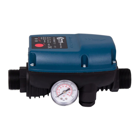
Voraussetzungen für Gebrauch und Installation
Die Kreiselpumpen Modell CA/4CA und die mehrstugen Elektropumpen Modell MSH und MSV PENTAX:
Eignen sich für das Pumpen von Frischwasser und Flüssigkeiten, die die Werkstoffe der Pumpe che-
misch und mecha nisch nicht angreifen und nicht explosiv sind und die keine Feststoffe und Fasern
enthalen, mit einer Temperatur von -15°C bis +90°C.
Es wird ausdrücklich darauf hingewiesen, dass eine hohe Temperatur der gepumpten Flüssigkeit, ihre
Dichte und ihre Viskosität sowie die Höhenlage vom Installationsort der Elektropumpe die Sauglei-
stung der Pumpen verringern.
Die Pumpen müssen an gut belüfteten, staubfreien und vor Witterungseinüssen geschützten Stan-
dorten installiert werden. Die Umgebugstemperatur muss zwischen 5°C und 40°C liegen. Die Pumpen
dürfen nicht an Standorten mit explosiver Atmosphäre installiert werden! Bei der Installation der
Pumpe muss ausreichend Freiraum für einen problemlosen Zugriff auf die Pumpe zur Durchführung
von Reparaturen oder zum Ausbauen der Pumpe gelassen werden. Es wird ausdrücklich darauf hin-
gewiesen, dass die Umgebungstemperatur und die Höhenlage am Installationsort der Elektropumpe
einen Einuss darauf nehmen, ob der Elektromotor voll ausgelastet werden kann. Zu hohe Umgebung-
stemperaturen und eine zu dünne Luft beeinträchtigen die Kühlung vom Elektromotor.
Die Pumpen sind auf eine Installation mit horizontaler Rotorachse (Modell CA/4CA und MSH) bzw. mit
vertikaler Rotorachse (Modell MSV) und nach unten gerichteten Stellfüßen bzw. Stelläche ausgelegt.
Aus Sicherheitsgründen wird dazu geraten, die Pumpen zu verschrauben und dazu die dafür vorgese-
henen Bohrungen an den Stellfüßen bzw. der Stelläche zu verwenden.
Mit geanschtem Stutzen und Gegenstutzen mit Gewinde ausgestattet sind:
• horizontale Modelle (CA/4CA und MSH): axiale Ansaugung und Druckleitung radial nach oben.
• vertikale Modelle (MSV): übereinander oder gegenüber angeordnete Stutzen mit unterer Ansaugung
und Druckleitung im oberen Bereich.
Die Pumpen eignen sich nicht für mehr als:
• 30 Einschaltzyklen pro Stunde in regelmäßigen Abständen: Modelle mit Nennleistung bis 2,2 kW.
• 15 Einschaltzyklen pro Stunde in regelmäßigen Abständen: Modelle mit Nennleistung von 3 bis 7,5 kW.
• 10 Einschaltzyklen pro Stunde in regelmäßigen Abständen: Modelle mit Nennleistung von 10 bis 37 kW.
Die maximal zulässige Einschaltzyklenzahl ist umso geringer, je höher die Leistung der Pumpe ist.
Wiederholtes Einschalten belastet die Pumpe weniger als den Elektromotor, an den die Pumpe an-
geschlossen ist. Für die Pumpen Modell CA/4CA wird deshalb auf das Handbuch vom Hersteller des
Elektromotors verwiesen.
Die Pumpen eignen sich für einen maximalen Betriebsdruck (entspricht dem Ansaugdruck + För-
derhöhe bei geschlossenem Ventil an der Druckleitung) von 10 bar bei den Modellen CA/4CA und von
30 bar bei den Modellen MSV/MSH. Die Pumpen eignen sich für den Dauerbetrieb und eine Höchstge-
schwindigkeit von 3600 Rpm (mit Ausnahme der Modelle CA65-315A, CA65-315C und CA65-315D, die
eine Höchstgeschwindigkeit von 1800 Rpm haben.
Installierung und Anreihung der pumpen CA/4CA
Die Installation und Ausrichtung der Pumpen darf nur von erfahrenem Fachpersonal durchgeführt werden.
Wenn die Pumpe zum Pumpen von Trinkwasser verwendet wird, muss sie vorher mit reichlich frischem
Wasser ausgespült werden, um eventuell vorhandene Verschmutzungen, Fett, Lackreste und Reste von
Testüssigkeiten vollständig zu entfernen. Die Pumpen mod. CA/4CA sehen eine Kupplung mit elektrischen
Standardmotoren mit Konstruktionsform IM B3 (IEC 34-7, IEC 72) mittels Basis und elastischer Verbin-
dungs-/Zugkupplung vor. Die Basis auf welcher die Pumpen und die Antriebsmaschine befestigt werden,
muss angesichts des Gewichtes der Gruppe und der Betriebsbelastungen entsprechend groß sein.
Das Heben und Transportieren der Pumpe und der Gruppe Pumpe-Motor erfolgt wie in Abb. 1 angegeben.
Während des Handlings muss sichergestellt werden, dass die Pumpe und die komplette Gruppe in waa-
grechter Stellung verbleiben, die Seile dürfen keinesfalls am freien Ende der Pumpe oder am Gewindehaken
des Motors befestigt werden.
Es ist verboten, die Seile am freien Ende der Pumpe oder an der Ringschraube vom Motor anzuschlagen, um
die gesamte Gruppe zu transportieren. Beim Transportieren der Pumpe ist größte Vorsicht geboten, da die
Maschinen bei falschem Transport beschädigt und die Funktionstüchtigkeit der Pumpe beeinträchtigt werden
kann - Abb. 1-.
Für den Zusammenbau der Gruppe Pumpe/Motor wie folgt vorgehen
die Verbindungsächen sorgfältig reinigen;
die Pumpe auf der Basis mit eigens vorgesehenen Verankerungen befestigen und die Befestigungsschrauben
des Stützfußes der Pumpe lockern;
Die Antriebsmaschine (Motor) auf der Basis positionieren;
Die beiden Halbverbindungen an Pumpen – und Motorseite an den entsprechenden Endpunkten der Welle
anbringen;
Die beiden Maschinen (Pumpe und Motor) verbinden und sicherstellen, dass ein Spielraum von 3-4 Mm zwischen
den zwei gegenübergestellten Flächen der Halbverbindungen, sowie der Pumpen – und Motorwellen besteht;
Mit einem Komparator oder einer Schieblehre und einem Lineal die Ausrichtung (Rundlauf und Parallellauf)
der Halbkupplungen und der Pumpen- und Motorwelle prüfen. Die Kontrollen müssen an 4 Stellen diametral
gegenübergestellt - Abb. 2-3 - ausgeführt werden -. Bei Notwendigkeit müssen eventuelle Unausgeglichen-
heiten durch Anbringung/Entfernung von Distanzteilen zwischen den Stützfüßen der Maschinen (Pumpe und
Motor) und Basis ausgeglichen werden;
die Befestigung der Gruppe auf der Basis durch Anbringung der Schutzvorrichtungen des Antriebs, sowie
INSTALLATIONS- UND BEDIENUNGSANWEISUNG FÜR DIE
PENTAX PUMPEN MODELL CA/4CA UND DIE MEHRSTUFI-
GEN PENTAX ELEKTROPUMPEN MODELL MSV/MSH
3
3
3
3
3
3
Pag. 14
jeglicher weiteren, für die Sicherheit notwendigen Schutzvorrichtungen beenden.
Die Gruppe Pumpe-Motor, welche auf einer einzigen Basis aus Prolstahl verbunden ist, muss folglich auf der
Betonplatte (entsprechend groß um alle Belastungen der Gruppe und der Rohrleitungen standzuhalten) gut
befestigt werden. Die Gruppe muss auf einer nivellierten Fläche installiert werden: die Basisplatte mit Unter-
legteilen nahe den Verankerungsbolzen (und in der Mitte im Falle von sehr großen Platten) unterstützen; Die
glatte Oberäche mit Hilfe der Anbringung einer Wasserwaage auf Welle und Zufuhröffnung überprüfen.
Zwischen Platte und Fundierung einen Freiraum von ungefähr 30-40 Mm zum Eingießen des Flüssigzemen-
tes für die Befestigung vorsehen - Abb. 3 -.
Erst nach Abhärten des Zementes die Fundierungsbolzen sorgfältig anziehen und die perfekte Anreihung
Pumpe-Motor, durch Befolgen des eben beschriebenen Vorgangs sicherstellen.
Die Anreihung muss kontrolliert werden sobald die Gruppe ihre Betriebstemperatur erreicht hat.
Solange die Fundierungen neu sind und die Anlage nicht bei allen Betriebsbedingungen abgenommen wurde,
muss die Anreihung regelmäßig kontrolliert und eventuell berichtigt werden.
Eine nicht korrekte Ausrichtung oder Positionierung der Gruppe oder ein falscher Anschluss der Leitungen
können Vibrationen verursachen und zu einem Anstieg vom Lärmpegel führen, sowie zu einem schnellen
Verschleiß der Gummidübel der Halbkupplungen sowie zu einer Beschädigung der Lager, der mechanischen
Dichtigkeit und der Bauteile.
Bei der Positionierung von Pumpe und Motor bitte darauf achten, dass hinter dem Motor ein entsprechender
Freiraum für die Luftzirkulation zur ausreichenden Kühlung des Motors vorgesehen wird.
Installierung der elektropumpen MSV/MSH
Die Pumpe und die Gruppe Pumpe-Motor nur durch sicheres Anseilen heben und transportieren. Keine sich
eventuell am Motor bendenden Haken verwenden, da diese nicht zum Tragen des Gewichts der gesamten
Gruppe ausgerichtet sind - Abb. 1 -.
Die Sicherheitsaspekte bei Kauf der alleinigen Pumpe in Verbindung mit einem anderen Motor als jenen in
unserem Katalog vorgesehenem, müssen vom Beauftragten, welcher diese Verbindungen vorgenommen
hat, gegeben werden.
Für den Fall, dass die Gruppe Pumpe-Motor schon installierungsfertig geliefert wird, genügt die Befesti-
gung der Maschine durch vorgesehene Verankerungshaken an eine ausreichend bemessene Zementsohle
entsprechend des Gewichtes der Gruppe und der Betriebsbelastungen (an der Ansaugbasis für vertikale
Maschinen Mod. MSV, an den Abstützungsbügeln der Absaugvorrichtung und der Verbindungsstange Pumpe-
Motor bei horizontalen Maschinen Mod. MSH).
Für den Fall, dass die Gruppe Pumpe-Motor nicht installierungsfertig geliefert wird muss folgend vorgegan-
gen werden:
bei Gruppen der Modelle MSV die Pumpe in vertikaler Position auf der Basis absetzen, in horizontaler
Position bei Modellen der Gruppe MSH;
den elektrischen Motor in Position bringen und der Pumpe nähern;
die Verbindungsächen sorgfältig reinigen und das Schutznetz am Verbindungs-Schubgelenk entfernen;
die beiden Halbverbindungen Seitens der Pumpe und des Motors an den entsprechenden Wellenenden
montieren;
die beiden Maschinen verbinden (Pumpe und Motor) und die Verbindungsschrauben der beiden Hal-
bverbindungen fest, unter Beachtung folgender Angaben anziehen
• jede Schraube muss mit einer nicht lösbaren Unterlegscheibe ausgestattet sein (Typ Grower),
• beim Anziehen die Hebung des drehbaren hydraulischen Teils beachten (Pumpenwelle und Drehteile);
die Befestigung der Gruppe auf der Basis durch Montage der Schutzvorrichtungen der Bewegungsü-
bertragung fertig stellen;
Um Schwingungsübertragungen an die Gruppe zu vermeiden müssen eventuelle Fehlanreihungen
zwischen den Verankerungspunkten der Gruppe und der Auiegeäche mit entsprechenden Unterla-
gen ausgeglichen werden.
Sicherstellen, dass bei der Positionierung der Gruppe Pumpe-Motor, an der hinteren Seite des Motors (bei
horizontalen Maschinen Mod. MSH) oder im oberen Teil (bei vertikalen Maschinen Mod. MSV) ausreichend
Freiraum für die Luftzirkulation zur Kühlung des Motors vorgesehen wird.
N.B. die Gruppen Pumpe-Motor der Serie MSV und MSH sind zur Verbindung durch Verbindungs-Schubge-
lenk an nicht standardmäßige elektrische Motoren PENTAX vorgesehen (aus Gründen wie Leistung/Größe,
sowie aus Gründen des Vorstehens der Welle).
Die im vorherigen Paragrafen angegebenen Schallwerte, beziehen sich auf Gruppen mit Motor PENTAX.
Rohrleitungen
Die Rohrleitungen müssen auf den eigens vorgesehenen Stützen befestigt und verankert und so angesch-
lossen werden, dass keine Kräfte, Spannungen und Schwingungen auf die Pumpe übertragen werden. Even-
tuelle Kompensatoren (exible Expandierungsverbindungen) korrekt, für die Aufnahme von Ausdehnungen
und Schwingungen anbringen - Abb. 4-5-6 -.
Der Innendurchmesser der Leitungen hängt von der Länge der Leitungen und dem erforderlichen Durchsatz
ab. Der Innendurchmesser muss so ausgelegt werden, dass die Geschwindigkeit der gepumpten Flüssigkeit
in der Ansaugleitung 1,4-1,5 m/s nicht übersteigt und in der Druckleitung 2,4-2,5 m/s. In jedem Fall muss
der Durchmesser der Leitungen mindestens dem Durchmesser der Pumpenstutzen entsprechen. Die Pumpe
muss so nahe wie möglich an der Entnahmestelle der Flüssigkeit installiert werden (NPSH und den Druckver-
lust in den Leitungen beachten).
Die Ansaugleitung muss: - Abb. 5 -
• so kurz wie möglich sein, ohne Verengungen und enge Rohrknie (bei Änderung vom Durchmesser
konische Verbindungsstücke verwenden).
• hermetisch dicht und für den Unterdruck geeignet sein, der beim Ansaugen durch die Pumpe entsteht.
• zur Pumpe hin abfallend verlegt werden, sodass die Bildung von Lufteinschlüssen verhindert wird,
die das Ansaugen der Pumpe beeinträchtigen oder sogar verhindern können.
3
3
3
3
3
3
3
3
Pag. 15
I – Italiano
DICHIARAZIONE DI INCORPORAZIONE
Si dichiara che i prodotti o quasimacchine in
elenco (models) sono conformi alle prescrizioni
delle direttive [D-CE] e costruiti nel rispetto
delle norme armonizzate [N-A] e che la doc-
umentazione tecnica pertinente è conforme
all’allegato VII B della Direttiva 2006/42/CE
UK – English
DECLARATION OF INCORPORATION
It is hereby declared that the products (mod-
els) in the list are compliant with the prescrip-
tions of Directives [D-CE] and built in compli-
ance with the harmonised regulations [N-A]
and that the pertaining technical documenta-
tion is compliant with attachment VII B of Di-
rective 2006/42/CE
D – Deutsch
EINBAUERKLÄRUNG
Es wird erklärt, dass die aufgeführten Produkte
oder die Teilmaschinen (Models) konform mit
den Vorschriften der Richtlinien [R- EG] sind
und dass sie gemäß den harmonisierten Nor-
men [H - N] hergestellt wurden und dass die
zugehörige technische Dokumentation kon-
form mit dem Anhang VII B der Richtlinie
2006/42/EG ist.
F – Français
DÉCLARATION D’INCORPORATION
Nous déclarons que les produits ou quasi-ma-
chines gurant dans la liste (models) sont con-
formes aux prescriptions des Directives [D-CE]
et sont fabriqués conformément aux normes
harmonisées [N-A]. En outre la documentation
technique spécique est conforme à la pièce
jointe VII B de la Directive 2006/42/CE.
S – Svenka
FÖRKLARAN OM INKORPORERING
Härmed förklaras att de angivna produkterna
eller delmaskinerna (models) överensstämmer
med föreskrifterna i direktivet [D-CE] och är
konstruerade med hänsyn till de harmonise-
rade normerna [N-A] och att den tillhörande
tekniska dokumentationen överensstämmer
med bilaga VII i direktivet 2006/45/CE
N – Norsk
ERKLÆRING FOR INNBYGGING
Erklærer at produktene eller delmaskinene på
listen (models) oppfyller kravene i direktivene
[D-CE] og at de er konstruerte i henhold til
de harmoniserte normene [N-A] og at den til-
hørende tekniske dokumentasjonen er i over-
ensstemmelse med vedlegg VII B i Direktivet
2006/42/EF.
D – Dansk
INKORPORERINGSERKLÆRING
Hermed erklæres at produkterne eller del-
maskinerne på listen (models) er konforme
med forskrifterne i direktiverne [D-CE] og
at de er fremstillet i overensstemmelse med
de harmoniserede standarder [N-A] samt at
den vedrørende tekniske dokumentation er i
overensstemmelse med bilag VII B i direktiv
2006/42/EF
NL – Nederland
INCORPORATIEVERKLARING
Hierbij verklaren wij dat de producten of deel-
machines uit de lijst (models) conform zijn
met de voorschriften van de richtlijnen [D-CE]
en gebouwd zijn in naleving van de geharmo-
niseerde normen [N-A] en dat de betreffende
technische documentatie conform is met bi-
jlage VII B van de Richtlijn 2006/42/CE
F – Suomi
LIITTÄMISVAKUUTUS
Vakuutamme, että luettelossa olevat koneet
tai puolivalmisteet (models) vastaavat direkti-
ivien [D-EY] asettamia vaatimuksia ja että ne
on valmistettu harmonisoitujen standardien
mukaisesti [H-S] ja että asiaan kuuluva te-
kninen dokumentaatio vastaa Euroopan neu-
voston direktiiviä 2006/42/EY liite VII B.
E– Español
DECLARACIÓN DE INCORPORACIÓN
Se declara que los productos o cuasi máquinas
que guran en la lista (models) son conformes
con lo establecido por las directivas [D-CE],
que han sido fabricados cumpliendo las nor-
mas armonizadas [N-A] y que la document-
ación técnica correspondiente es conforme con
el anexo VII B de la Directiva 2006/42/CE
P– Portoguês
DECLARAÇÃO DE INCORPORAÇÃO
Declara-se que os produtos ou quase-máqui-
nas na lista (models) estão em conformidade
com as prescrições das diretivas [D-CE], fab-
ricados no respeito das normas harmonizadas
[N-A] e que a documentação técnica pertinen-
te está em conformidade com o alegado VII B
da Diretiva 2006/42/CE.
EL – ΕΛΛΗΝΙΚΑ
ΔΗΛΩΣΗ ΕΝΣΩΜΑΤΩΣΗΣ
Δηλώνει ότι τα προϊόντα ή τα μηχανήματα
του καταλόγου (models) συνάδουν με τις
προδιαγραφές των οδηγιών [D-CE] και έχουν
κατασκευαστεί τηρώντας τους εναρμονισμένους
κανονισμούς [N-A] και την σχετική τεχνική
τεκμηρίωση και συμμορφώνονται με το
παράρτημα VII B της Οδηγίας 2006/42/CE
TR – Türkçe
ORTAKLIK BEYANI
Listedeki (models) ürün ve makinelerin, [D-
CE] direktieri yönergelerine uygun oldukları
ve ilgili harmonize [N-A] direktiere uyularak
imal edildikleri, ve ilgili teknik dokümantasy-
onun 2006/42/CE Direktinin VII B ekine uy-
gun olduğu beyan edilir.
Pag. 4
(D-CE)
98/37/CE; 2006/42/CE; 2000/14/CE (followed procedure: annex V).
(N-A)
EN ISO 12100; EN ISO 14121; EN ISO 3744;
EN 733 (main dimensions and rated performance) for models CA
/ 4CA
models:
CA / 4CA
Acoustic pressure level: <80 dB (A) – when installed following the
instructions indicated in this manual and according to the state of
the art rules.
Pump-motor sound emission: consider even the sound level de-
clared by the electric motor manufacturer.
MSV / MSH (hydraulic part)
Acoustic pressure level):< 90 dB(A) – when installed following the
instructions indicated in this manual and according to the state of
the art rules.
Pump-motor sound emission: consider even the sound level de-
clared by the electric motor manufacturer.
Manufacturer and depositary of tecnical documentation:
PENTAX S.p.A.
Viale dell’industria, 1
37040 Veronella (VR) - Italia
Gianluigi Pedrollo (President)
Veronella (Vr), 01/01/2011
Pag. 5
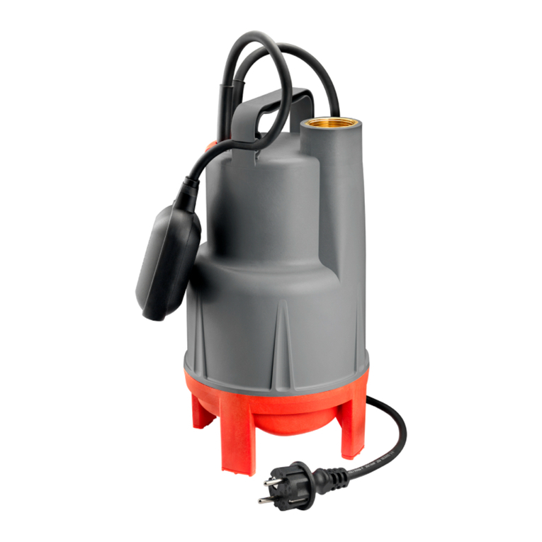
Voraussetzungen für Gebrauch und Installation
Die Kreiselpumpen Modell CA/4CA und die mehrstugen Elektropumpen Modell MSH und MSV PENTAX:
Eignen sich für das Pumpen von Frischwasser und Flüssigkeiten, die die Werkstoffe der Pumpe che-
misch und mecha nisch nicht angreifen und nicht explosiv sind und die keine Feststoffe und Fasern
enthalen, mit einer Temperatur von -15°C bis +90°C.
Es wird ausdrücklich darauf hingewiesen, dass eine hohe Temperatur der gepumpten Flüssigkeit, ihre
Dichte und ihre Viskosität sowie die Höhenlage vom Installationsort der Elektropumpe die Sauglei-
stung der Pumpen verringern.
Die Pumpen müssen an gut belüfteten, staubfreien und vor Witterungseinüssen geschützten Stan-
dorten installiert werden. Die Umgebugstemperatur muss zwischen 5°C und 40°C liegen. Die Pumpen
dürfen nicht an Standorten mit explosiver Atmosphäre installiert werden! Bei der Installation der
Pumpe muss ausreichend Freiraum für einen problemlosen Zugriff auf die Pumpe zur Durchführung
von Reparaturen oder zum Ausbauen der Pumpe gelassen werden. Es wird ausdrücklich darauf hin-
gewiesen, dass die Umgebungstemperatur und die Höhenlage am Installationsort der Elektropumpe
einen Einuss darauf nehmen, ob der Elektromotor voll ausgelastet werden kann. Zu hohe Umgebung-
stemperaturen und eine zu dünne Luft beeinträchtigen die Kühlung vom Elektromotor.
Die Pumpen sind auf eine Installation mit horizontaler Rotorachse (Modell CA/4CA und MSH) bzw. mit
vertikaler Rotorachse (Modell MSV) und nach unten gerichteten Stellfüßen bzw. Stelläche ausgelegt.
Aus Sicherheitsgründen wird dazu geraten, die Pumpen zu verschrauben und dazu die dafür vorgese-
henen Bohrungen an den Stellfüßen bzw. der Stelläche zu verwenden.
Mit geanschtem Stutzen und Gegenstutzen mit Gewinde ausgestattet sind:
• horizontale Modelle (CA/4CA und MSH): axiale Ansaugung und Druckleitung radial nach oben.
• vertikale Modelle (MSV): übereinander oder gegenüber angeordnete Stutzen mit unterer Ansaugung
und Druckleitung im oberen Bereich.
Die Pumpen eignen sich nicht für mehr als:
• 30 Einschaltzyklen pro Stunde in regelmäßigen Abständen: Modelle mit Nennleistung bis 2,2 kW.
• 15 Einschaltzyklen pro Stunde in regelmäßigen Abständen: Modelle mit Nennleistung von 3 bis 7,5 kW.
• 10 Einschaltzyklen pro Stunde in regelmäßigen Abständen: Modelle mit Nennleistung von 10 bis 37 kW.
Die maximal zulässige Einschaltzyklenzahl ist umso geringer, je höher die Leistung der Pumpe ist.
Wiederholtes Einschalten belastet die Pumpe weniger als den Elektromotor, an den die Pumpe an-
geschlossen ist. Für die Pumpen Modell CA/4CA wird deshalb auf das Handbuch vom Hersteller des
Elektromotors verwiesen.
Die Pumpen eignen sich für einen maximalen Betriebsdruck (entspricht dem Ansaugdruck + För-
derhöhe bei geschlossenem Ventil an der Druckleitung) von 10 bar bei den Modellen CA/4CA und von
30 bar bei den Modellen MSV/MSH. Die Pumpen eignen sich für den Dauerbetrieb und eine Höchstge-
schwindigkeit von 3600 Rpm (mit Ausnahme der Modelle CA65-315A, CA65-315C und CA65-315D, die
eine Höchstgeschwindigkeit von 1800 Rpm haben.
Installierung und Anreihung der pumpen CA/4CA
Die Installation und Ausrichtung der Pumpen darf nur von erfahrenem Fachpersonal durchgeführt werden.
Wenn die Pumpe zum Pumpen von Trinkwasser verwendet wird, muss sie vorher mit reichlich frischem
Wasser ausgespült werden, um eventuell vorhandene Verschmutzungen, Fett, Lackreste und Reste von
Testüssigkeiten vollständig zu entfernen. Die Pumpen mod. CA/4CA sehen eine Kupplung mit elektrischen
Standardmotoren mit Konstruktionsform IM B3 (IEC 34-7, IEC 72) mittels Basis und elastischer Verbin-
dungs-/Zugkupplung vor. Die Basis auf welcher die Pumpen und die Antriebsmaschine befestigt werden,
muss angesichts des Gewichtes der Gruppe und der Betriebsbelastungen entsprechend groß sein.
Das Heben und Transportieren der Pumpe und der Gruppe Pumpe-Motor erfolgt wie in Abb. 1 angegeben.
Während des Handlings muss sichergestellt werden, dass die Pumpe und die komplette Gruppe in waa-
grechter Stellung verbleiben, die Seile dürfen keinesfalls am freien Ende der Pumpe oder am Gewindehaken
des Motors befestigt werden.
Es ist verboten, die Seile am freien Ende der Pumpe oder an der Ringschraube vom Motor anzuschlagen, um
die gesamte Gruppe zu transportieren. Beim Transportieren der Pumpe ist größte Vorsicht geboten, da die
Maschinen bei falschem Transport beschädigt und die Funktionstüchtigkeit der Pumpe beeinträchtigt werden
kann - Abb. 1-.
Für den Zusammenbau der Gruppe Pumpe/Motor wie folgt vorgehen
die Verbindungsächen sorgfältig reinigen;
die Pumpe auf der Basis mit eigens vorgesehenen Verankerungen befestigen und die Befestigungsschrauben
des Stützfußes der Pumpe lockern;
Die Antriebsmaschine (Motor) auf der Basis positionieren;
Die beiden Halbverbindungen an Pumpen – und Motorseite an den entsprechenden Endpunkten der Welle
anbringen;
Die beiden Maschinen (Pumpe und Motor) verbinden und sicherstellen, dass ein Spielraum von 3-4 Mm zwischen
den zwei gegenübergestellten Flächen der Halbverbindungen, sowie der Pumpen – und Motorwellen besteht;
Mit einem Komparator oder einer Schieblehre und einem Lineal die Ausrichtung (Rundlauf und Parallellauf)
der Halbkupplungen und der Pumpen- und Motorwelle prüfen. Die Kontrollen müssen an 4 Stellen diametral
gegenübergestellt - Abb. 2-3 - ausgeführt werden -. Bei Notwendigkeit müssen eventuelle Unausgeglichen-
heiten durch Anbringung/Entfernung von Distanzteilen zwischen den Stützfüßen der Maschinen (Pumpe und
Motor) und Basis ausgeglichen werden;
die Befestigung der Gruppe auf der Basis durch Anbringung der Schutzvorrichtungen des Antriebs, sowie
INSTALLATIONS- UND BEDIENUNGSANWEISUNG FÜR DIE
PENTAX PUMPEN MODELL CA/4CA UND DIE MEHRSTUFI-
GEN PENTAX ELEKTROPUMPEN MODELL MSV/MSH
3
3
3
3
3
3
Pag. 14
jeglicher weiteren, für die Sicherheit notwendigen Schutzvorrichtungen beenden.
Die Gruppe Pumpe-Motor, welche auf einer einzigen Basis aus Prolstahl verbunden ist, muss folglich auf der
Betonplatte (entsprechend groß um alle Belastungen der Gruppe und der Rohrleitungen standzuhalten) gut
befestigt werden. Die Gruppe muss auf einer nivellierten Fläche installiert werden: die Basisplatte mit Unter-
legteilen nahe den Verankerungsbolzen (und in der Mitte im Falle von sehr großen Platten) unterstützen; Die
glatte Oberäche mit Hilfe der Anbringung einer Wasserwaage auf Welle und Zufuhröffnung überprüfen.
Zwischen Platte und Fundierung einen Freiraum von ungefähr 30-40 Mm zum Eingießen des Flüssigzemen-
tes für die Befestigung vorsehen - Abb. 3 -.
Erst nach Abhärten des Zementes die Fundierungsbolzen sorgfältig anziehen und die perfekte Anreihung
Pumpe-Motor, durch Befolgen des eben beschriebenen Vorgangs sicherstellen.
Die Anreihung muss kontrolliert werden sobald die Gruppe ihre Betriebstemperatur erreicht hat.
Solange die Fundierungen neu sind und die Anlage nicht bei allen Betriebsbedingungen abgenommen wurde,
muss die Anreihung regelmäßig kontrolliert und eventuell berichtigt werden.
Eine nicht korrekte Ausrichtung oder Positionierung der Gruppe oder ein falscher Anschluss der Leitungen
können Vibrationen verursachen und zu einem Anstieg vom Lärmpegel führen, sowie zu einem schnellen
Verschleiß der Gummidübel der Halbkupplungen sowie zu einer Beschädigung der Lager, der mechanischen
Dichtigkeit und der Bauteile.
Bei der Positionierung von Pumpe und Motor bitte darauf achten, dass hinter dem Motor ein entsprechender
Freiraum für die Luftzirkulation zur ausreichenden Kühlung des Motors vorgesehen wird.
Installierung der elektropumpen MSV/MSH
Die Pumpe und die Gruppe Pumpe-Motor nur durch sicheres Anseilen heben und transportieren. Keine sich
eventuell am Motor bendenden Haken verwenden, da diese nicht zum Tragen des Gewichts der gesamten
Gruppe ausgerichtet sind - Abb. 1 -.
Die Sicherheitsaspekte bei Kauf der alleinigen Pumpe in Verbindung mit einem anderen Motor als jenen in
unserem Katalog vorgesehenem, müssen vom Beauftragten, welcher diese Verbindungen vorgenommen
hat, gegeben werden.
Für den Fall, dass die Gruppe Pumpe-Motor schon installierungsfertig geliefert wird, genügt die Befesti-
gung der Maschine durch vorgesehene Verankerungshaken an eine ausreichend bemessene Zementsohle
entsprechend des Gewichtes der Gruppe und der Betriebsbelastungen (an der Ansaugbasis für vertikale
Maschinen Mod. MSV, an den Abstützungsbügeln der Absaugvorrichtung und der Verbindungsstange Pumpe-
Motor bei horizontalen Maschinen Mod. MSH).
Für den Fall, dass die Gruppe Pumpe-Motor nicht installierungsfertig geliefert wird muss folgend vorgegan-
gen werden:
bei Gruppen der Modelle MSV die Pumpe in vertikaler Position auf der Basis absetzen, in horizontaler
Position bei Modellen der Gruppe MSH;
den elektrischen Motor in Position bringen und der Pumpe nähern;
die Verbindungsächen sorgfältig reinigen und das Schutznetz am Verbindungs-Schubgelenk entfernen;
die beiden Halbverbindungen Seitens der Pumpe und des Motors an den entsprechenden Wellenenden
montieren;
die beiden Maschinen verbinden (Pumpe und Motor) und die Verbindungsschrauben der beiden Hal-
bverbindungen fest, unter Beachtung folgender Angaben anziehen
• jede Schraube muss mit einer nicht lösbaren Unterlegscheibe ausgestattet sein (Typ Grower),
• beim Anziehen die Hebung des drehbaren hydraulischen Teils beachten (Pumpenwelle und Drehteile);
die Befestigung der Gruppe auf der Basis durch Montage der Schutzvorrichtungen der Bewegungsü-
bertragung fertig stellen;
Um Schwingungsübertragungen an die Gruppe zu vermeiden müssen eventuelle Fehlanreihungen
zwischen den Verankerungspunkten der Gruppe und der Auiegeäche mit entsprechenden Unterla-
gen ausgeglichen werden.
Sicherstellen, dass bei der Positionierung der Gruppe Pumpe-Motor, an der hinteren Seite des Motors (bei
horizontalen Maschinen Mod. MSH) oder im oberen Teil (bei vertikalen Maschinen Mod. MSV) ausreichend
Freiraum für die Luftzirkulation zur Kühlung des Motors vorgesehen wird.
N.B. die Gruppen Pumpe-Motor der Serie MSV und MSH sind zur Verbindung durch Verbindungs-Schubge-
lenk an nicht standardmäßige elektrische Motoren PENTAX vorgesehen (aus Gründen wie Leistung/Größe,
sowie aus Gründen des Vorstehens der Welle).
Die im vorherigen Paragrafen angegebenen Schallwerte, beziehen sich auf Gruppen mit Motor PENTAX.
Rohrleitungen
Die Rohrleitungen müssen auf den eigens vorgesehenen Stützen befestigt und verankert und so angesch-
lossen werden, dass keine Kräfte, Spannungen und Schwingungen auf die Pumpe übertragen werden. Even-
tuelle Kompensatoren (exible Expandierungsverbindungen) korrekt, für die Aufnahme von Ausdehnungen
und Schwingungen anbringen - Abb. 4-5-6 -.
Der Innendurchmesser der Leitungen hängt von der Länge der Leitungen und dem erforderlichen Durchsatz
ab. Der Innendurchmesser muss so ausgelegt werden, dass die Geschwindigkeit der gepumpten Flüssigkeit
in der Ansaugleitung 1,4-1,5 m/s nicht übersteigt und in der Druckleitung 2,4-2,5 m/s. In jedem Fall muss
der Durchmesser der Leitungen mindestens dem Durchmesser der Pumpenstutzen entsprechen. Die Pumpe
muss so nahe wie möglich an der Entnahmestelle der Flüssigkeit installiert werden (NPSH und den Druckver-
lust in den Leitungen beachten).
Die Ansaugleitung muss: - Abb. 5 -
• so kurz wie möglich sein, ohne Verengungen und enge Rohrknie (bei Änderung vom Durchmesser
konische Verbindungsstücke verwenden).
• hermetisch dicht und für den Unterdruck geeignet sein, der beim Ansaugen durch die Pumpe entsteht.
• zur Pumpe hin abfallend verlegt werden, sodass die Bildung von Lufteinschlüssen verhindert wird,
die das Ansaugen der Pumpe beeinträchtigen oder sogar verhindern können.
3
3
3
3
3
3
3
3
Pag. 15
I – Italiano
DICHIARAZIONE DI INCORPORAZIONE
Si dichiara che i prodotti o quasimacchine in
elenco (models) sono conformi alle prescrizioni
delle direttive [D-CE] e costruiti nel rispetto
delle norme armonizzate [N-A] e che la doc-
umentazione tecnica pertinente è conforme
all’allegato VII B della Direttiva 2006/42/CE
UK – English
DECLARATION OF INCORPORATION
It is hereby declared that the products (mod-
els) in the list are compliant with the prescrip-
tions of Directives [D-CE] and built in compli-
ance with the harmonised regulations [N-A]
and that the pertaining technical documenta-
tion is compliant with attachment VII B of Di-
rective 2006/42/CE
D – Deutsch
EINBAUERKLÄRUNG
Es wird erklärt, dass die aufgeführten Produkte
oder die Teilmaschinen (Models) konform mit
den Vorschriften der Richtlinien [R- EG] sind
und dass sie gemäß den harmonisierten Nor-
men [H - N] hergestellt wurden und dass die
zugehörige technische Dokumentation kon-
form mit dem Anhang VII B der Richtlinie
2006/42/EG ist.
F – Français
DÉCLARATION D’INCORPORATION
Nous déclarons que les produits ou quasi-ma-
chines gurant dans la liste (models) sont con-
formes aux prescriptions des Directives [D-CE]
et sont fabriqués conformément aux normes
harmonisées [N-A]. En outre la documentation
technique spécique est conforme à la pièce
jointe VII B de la Directive 2006/42/CE.
S – Svenka
FÖRKLARAN OM INKORPORERING
Härmed förklaras att de angivna produkterna
eller delmaskinerna (models) överensstämmer
med föreskrifterna i direktivet [D-CE] och är
konstruerade med hänsyn till de harmonise-
rade normerna [N-A] och att den tillhörande
tekniska dokumentationen överensstämmer
med bilaga VII i direktivet 2006/45/CE
N – Norsk
ERKLÆRING FOR INNBYGGING
Erklærer at produktene eller delmaskinene på
listen (models) oppfyller kravene i direktivene
[D-CE] og at de er konstruerte i henhold til
de harmoniserte normene [N-A] og at den til-
hørende tekniske dokumentasjonen er i over-
ensstemmelse med vedlegg VII B i Direktivet
2006/42/EF.
D – Dansk
INKORPORERINGSERKLÆRING
Hermed erklæres at produkterne eller del-
maskinerne på listen (models) er konforme
med forskrifterne i direktiverne [D-CE] og
at de er fremstillet i overensstemmelse med
de harmoniserede standarder [N-A] samt at
den vedrørende tekniske dokumentation er i
overensstemmelse med bilag VII B i direktiv
2006/42/EF
NL – Nederland
INCORPORATIEVERKLARING
Hierbij verklaren wij dat de producten of deel-
machines uit de lijst (models) conform zijn
met de voorschriften van de richtlijnen [D-CE]
en gebouwd zijn in naleving van de geharmo-
niseerde normen [N-A] en dat de betreffende
technische documentatie conform is met bi-
jlage VII B van de Richtlijn 2006/42/CE
F – Suomi
LIITTÄMISVAKUUTUS
Vakuutamme, että luettelossa olevat koneet
tai puolivalmisteet (models) vastaavat direkti-
ivien [D-EY] asettamia vaatimuksia ja että ne
on valmistettu harmonisoitujen standardien
mukaisesti [H-S] ja että asiaan kuuluva te-
kninen dokumentaatio vastaa Euroopan neu-
voston direktiiviä 2006/42/EY liite VII B.
E– Español
DECLARACIÓN DE INCORPORACIÓN
Se declara que los productos o cuasi máquinas
que guran en la lista (models) son conformes
con lo establecido por las directivas [D-CE],
que han sido fabricados cumpliendo las nor-
mas armonizadas [N-A] y que la document-
ación técnica correspondiente es conforme con
el anexo VII B de la Directiva 2006/42/CE
P– Portoguês
DECLARAÇÃO DE INCORPORAÇÃO
Declara-se que os produtos ou quase-máqui-
nas na lista (models) estão em conformidade
com as prescrições das diretivas [D-CE], fab-
ricados no respeito das normas harmonizadas
[N-A] e que a documentação técnica pertinen-
te está em conformidade com o alegado VII B
da Diretiva 2006/42/CE.
EL – ΕΛΛΗΝΙΚΑ
ΔΗΛΩΣΗ ΕΝΣΩΜΑΤΩΣΗΣ
Δηλώνει ότι τα προϊόντα ή τα μηχανήματα
του καταλόγου (models) συνάδουν με τις
προδιαγραφές των οδηγιών [D-CE] και έχουν
κατασκευαστεί τηρώντας τους εναρμονισμένους
κανονισμούς [N-A] και την σχετική τεχνική
τεκμηρίωση και συμμορφώνονται με το
παράρτημα VII B της Οδηγίας 2006/42/CE
TR – Türkçe
ORTAKLIK BEYANI
Listedeki (models) ürün ve makinelerin, [D-
CE] direktieri yönergelerine uygun oldukları
ve ilgili harmonize [N-A] direktiere uyularak
imal edildikleri, ve ilgili teknik dokümantasy-
onun 2006/42/CE Direktinin VII B ekine uy-
gun olduğu beyan edilir.
Pag. 4
(D-CE)
98/37/CE; 2006/42/CE; 2000/14/CE (followed procedure: annex V).
(N-A)
EN ISO 12100; EN ISO 14121; EN ISO 3744;
EN 733 (main dimensions and rated performance) for models CA
/ 4CA
models:
CA / 4CA
Acoustic pressure level: <80 dB (A) – when installed following the
instructions indicated in this manual and according to the state of
the art rules.
Pump-motor sound emission: consider even the sound level de-
clared by the electric motor manufacturer.
MSV / MSH (hydraulic part)
Acoustic pressure level):< 90 dB(A) – when installed following the
instructions indicated in this manual and according to the state of
the art rules.
Pump-motor sound emission: consider even the sound level de-
clared by the electric motor manufacturer.
Manufacturer and depositary of tecnical documentation:
PENTAX S.p.A.
Viale dell’industria, 1
37040 Veronella (VR) - Italia
Gianluigi Pedrollo (President)
Veronella (Vr), 01/01/2011
Pag. 5

Zum Ansaugen mit der Pumpe ein Bodenventil mit Saugkorb einsetzen. Damit die Elektropumpe korrekt
funktioniert, muss das Ende der Ansaugleitung ins Wasser getaucht werden, wobei der Abstand zur Wasse-
roberäche mindestens doppelt so groß sein muss wie der Leitungsdurchmesser. Bei Installation der Pumpe
unter der Wasserdruckhöhe einen Schieber einsetzen. Wenn ein Schieber installiert wird, muss dieser so
montiert werden, dass die Achse vom Handrad horizontal ist. - Abb. 6 -.
Die Druckleitung sollte mit einem Rückschlagventil und einem Durchussregelventil ausgerüstet
werden. Das Rückschlagventil muss vor dem Durchussregelventil installiert werden und schützt die
Pumpe vor Wasserschlägen. Außerdem verhindert das Rückschlagventil das ungewollte Rückießen
durch das Laufrad bei plötzlichem Abschalten der Elektropumpe. Das Durchussregelventil dient zur
Regulierung von Durchsatz, Förderhöher und abgenommener Leistung. An der Druckleitung muss ein
Manometer installiert werden - Abb. 4-5-6 -.
Nach der Installation und vor Inbetriebnahme vom Pumpenaggregat (Pumpe Modell CA/4CA) prüfen, ob die
Verankerungsbolzen fest angezogen sind. Den Anschluss der Leitungen und die Ausrichtung der Kupplung
(Pumpe-Motor) prüfen und dazu die oben beschriebene Prozedur beachten.
Stromanschluss der Elektropumpen Modell CA/4CA
Die elektrischen Anschlüsse müssen von qualiziertem Personal, gemäß Gesetzvorschriften, geltender Normen,
sowie unter Beachtung der vom Motorhersteller angegebenen Anleitungen vorgenommen werden.
Bitte immer die Erdung der Gruppe Pumpe-Motor vornehmen; außerdem bedarf es der Anbringung einer entspre-
chenden elektrischen Schutzvorrichtung (Magnetthermischer Schalter und Differentialschalter) um so eine Uni-
polare Unterbrechung vom Netz und eine Öffnungsdistanz der Kontakte von mindestens 3 mm zuzusichern.
In jedem Fall müssen die Hinweise vom Hersteller des Elektromotor beachtet werden.
Stromanschluss der Elektropumpen Modell MSV/MSH
Die Stromkabel müssen unter Berücksichtigung ihrer Länge und den Angeben zur Stromversorgung auf
dem Typenschild der Elektropumpe korrekt ausgelegt werden. Die Enden der Leiter und der Erdung so
vorbereiten, dass die Leiter beim Anziehen der Klemmen und der Erdungsschraube nicht herausrutschen
können. Der Stromanschluss darf nur von einem qualizierten Elektriker unter Beachtung der geltenden
Gesetzgebung durchgeführt werden.
Sicherstellen, dass die Spannung und Frequenz vom Stromnetz mit den Daten auf dem Typenschild der
Elektropumpe übereinstimmen. Dann die Klemmen unter Beachtung vom Schaltplan auf S. 4 bzw. im De-
ckel der Klemmleiste anschließen. Die Erdung der Elektropumpe durchführen und dazu die entsprechende
Klemme verwenden. Sicherstellen, dass das Stromnetz über eine ordnungsmäßige Erdung verfügt und die
Erdung der Elektropumpe korrekt durchgeführt worden ist.
Es bedarf immer eines angemessenen elektrischen Schutzes (Magnetthermischer Schalter und Differential-
schalter mit Zuschaltschwelle ≤ 30 mA), welche in der Lage sind das gänzliche Abschalten des Netzes mit
einer Öffnungsdistanz der Kontakte von mindestens 3 mm zu gewährleisten
Einschalten
Vor dem Einschalten der Pumpe sicherstellen, dass sich die Antriebswelle von Hand frei drehen lässt. Vor
dem Einschalten die Elektropumpe, Pumpenkörper und Ansaugleitung vollständig über die dafür vorgesehe-
ne Öffnung mit Flüssigkeit füllen - Abb. 7 -. Es ist streng verboten, die Pumpe trocken laufen zu lassen! Die
Pumpe auf keinen Fall über einen längeren Zeitraum (mehr als 2-3 Minuten) mit verschlossener Druckleitung
laufen lassen, da sich dadurch die gepumpte Flüssigkeit erhitzt, was zu Schäden an der Elektropumpe und
deren Komponenten führen kann. Es wird dazu geraten, die Pumpe mit einer Mindestfördermenge laufen zu
lassen, die mindestens 10% der Nennförderleistung der Pumpe entspricht.
Wenn die Pumpe läuft, ohne dass Wasser angesaugt wird, kann sich die in der Pumpe enthaltene Flüssigkeit
erhitzen. Bei Durchführung von Eingriffen gleich welcher Art an der Pumpe (Entlüften, Nachfüllen, usw.)
kann daher Verbrennungsgefahr bestehen!
Alle Elektropumpen müssen sich im Uhrzeigersinn drehen, wenn man von der Gebläseseite aus auf den Motor
schaut. Bei Dreiphasen-Elektropumpen die korrekte Drehrichtung prüfen und ggf. die beiden Phasen vertauschen.
Vor dem Start die Vorschleuse vollständig schließen. Dann, nach der Inbetriebnahme der Pumpeneinheit,
öffnet man die Vorschleuse langsam und stellt den dynamischen Arbeitspunkt innerhalb der auf dem Kenn-
zeichnungsschild der Pumpe angegebenen Grenzen ein. Außerdem muss überprüft werden, dass die Stro-
maufnahme des Elektromotors den Wert auf dem Kennzeichnungschild nicht überschreitet. Sicherstellen,
dass die Pumpe in ihrem auf dem Kennzeichnungsschild angegebenem Normalleistungsbereich arbeitet;
sollte dies nicht der Fall sein, muss die Vorschleuse auf der Zufuhrleitung bzw. die Druckwerte für den Eingriff
eventueller Druckwächter korrekt eingestellt werden.
Wartung
Die Pumpen machen keine besondere Wartung erforderlich. Bei Frostgefahr oder bei längerem Abschalten
der Pumpe sollten die Pumpe und die Leitungen vollständig geleert werden - Abb. 7 -. Vor dem erneuten
Einschalten der Elektropumpe sicherstellen, dass die Antriebswelle nicht durch Verkrustungen oder anderes
blockiert ist, und den Pumpenkörper und die Ansaugleitung vollständig mit Flüssigkeit füllen.
Bei Eingriffen an der Pumpe die Schieber an Saug- und Druckleitung schließen und die in der Elektropumpe
enthaltene Flüssigkeit über die entsprechenden Öffnungen ablassen. Vorsicht! Die gepumpte Flüssigkeit
kann heiß sein oder unter Druck stehen!
WICHTIGER HINWEIS: Vor Durchführung von Wartungseingriffen u/o Repara-
turen den Strom abschalten!
Außerbetriebnahme
Diese Pumpen machen keine besonderen Prozeduren zur Außerbetriebnahme oder Verschrottung erfor-
derlich. Entsorgung, Rückgewinnung, Wiederverwertung und Recycling der Materialien müssen unter Be-
achtung der vor Ort geltenden gesetzlichen Vorschriften erfolgen.
Pag. 16
Conditions d’utilisation et installation
Les pompes centrifuges mod. CA/4CA et les électropompes centrifuges multicellulaires mod. MSH et MSV
PENTAX :
sont adaptées pour le pompage d’eau propre et de liquides chimiquement et mécaniquement non
agressifs pour les matériaux de la pompe, non explosifs, qui ne contiennent pas des corps solides ou
breux, ayant une température allant de -15°C jusqu’à +90 °C;
Ne pas oublier qu’une température élevée du liquide à pomper, sa densité et viscosité, de même que
l’altitude du lieu d’installation de l’électropompe, limite la possibilité/capacité d’aspiration des pompes.
Elles doivent être installées dans des lieux bien aérés, non poussiéreux, protégés contre les intempéri-
es, avec une température ambiante comprise entre 5 et 40 °C, dans une atmosphère rigoureusement
non explosive. Lors de l’installation de la machine, il est conseillé d’évaluer avec attention l’éventuel
espace nécessaire pour les opérations de réparation ou de retrait de celle-ci. Ne pas oublier que la tem-
pérature ambiante et l’altitude du lieu d’installation de l’électropompe inuencent la possibilité de faire
fonctionner le moteur électrique sous pleine charge: en effet, aussi bien les températures ambiantes
élevées que la moindre densité de l’air réduisent le refroidissement du moteur électrique .
Sont réalisées avec l’axe du rotor horizontal (mod. CA/4CA et MSH) ou vertical (mod. MSV) et avec
les pieds/socle d’appui en bas; pour des raisons de sécurité, il est conseillé de xer l’électropompe en
utilisant les trous prévus à cet effet sur les pieds/base d’appui.
Sont équipées de brides munies d’une contre-bride letée
• modèles horizontaux (CA/4CA ET MSH) : aspiration axiale et refoulement radial vers le haut ;
• modèles verticaux (MSV) : brides superposées ou opposées, avec aspiration dans la partie inférieure
et refoulement dans la partie supérieure.
Elles sont conçues pour supporter un maximum de :
• 30 démarrages par heure, à intervalles réguliers : modèles avec puissance nominale jusqu’à 2.2 kW ;
• 15 démarrages par heure, à intervalles réguliers : modèles avec puissance nominale de 3 à 7,5 kW ;
• 10 démarrages par heure, à intervalles réguliers : modèles avec puissance nominale de 10 à 37 kW ;
Plus la puissance de la machine est élevée, moins le nombre de démarrages admissibles est élevé.
Plus qu’à la pompe, les démarrages répétés peuvent créer des problèmes au moteur électrique accou-
plé à celle-ci ; il est donc conseillé, pour les pompes mod. CA/4CA, de se référer à la documentation
fournie par le fabricant du moteur.
elles peuvent supporter une pression de fonctionnement maximum (égale à la pression en aspiration
+ hauteur manométrique avec la vanne de refoulement fermée) de 10 bar pour les pompes mod.
CA/4CA et de 30 bars pour les pompes mod. MSV/H. Peuvent fonctionner en service continu et tra-
vailler à une vitesse maximum égale à 3600 min-1 (à l’exception des mod. CA65-315A, CA65-315-B,
CA65-315C, CA65-315D pour lesquels la vitesse maximum égale à 1800 min-1).
Installation et alignement des pompes CA/4CA
L’installation et l’alignement doivent être exécutés par du personnel expert et qualié.
Si la pompe est utilisée pour pomper de l’eau potable, elle doit d’abord être abondamment lavée avec de
l’eau propre an d’éliminer les éventuelles particules étrangères, graisses, résidus de peinture et liquides
d’essai. Les pompes mod. CA/4CA sont prévues pour l’accouplement à des moteurs électriques standards
du type de construction IM B3 (IEC 34-7, IEC 72) par l’intermédiaire d’un socle et d’un joint élastique de
raccordement/entraînement. Le socle sur lequel seront xées la pompe et la machine motrice, doit être de
dimensions appropriées par rapport au poids du groupe et aux sollicitations de fonctionnement.
Soulever et transporter la pompe et le groupe pompe-moteur comme indiqué à la g. 1. Pendant la manu-
tention on doit s’assurer que la pompe ainsi que tout le groupe restent bien en position horizontale; on ne
peut, en aucun cas, lier les cordages à l’extrémité libre de la pompe ou à l’œillet du moteure pour déplacer
tout le groupe. Procéder avec attention lors de la manutention des pompes car des manoeuvres erronées
peuvent endommager les machines et compromettre leur fonctionnement correct. – Fig. 1 -
Pour l’assemblage pompe moteur, effectuer les opérations suivantes :
Nettoyer soigneusement les surfaces d’accouplement ;
Fixer la pompe sur le socle en utilisant les points d’ancrage prévus à cet effet et desserrer les vis de xation
du pied d’appui du support de la pompe;
Placer la machine motrice (moteur) sur le socle;
Monter les deux joints, côté pompe et côté moteur, sur les extrémités d’arbre correspondantes ;
Accoupler les deux machines (pompe et moteur) en vériant qu’il reste un jour de 3 à 4 mm entre les deux
faces opposées des joints et des arbres pompe et moteur;
à l’aide d’un comparateur ou d’un calibre d’épaisseur et d’une règle, contrôler l’alignement (concentricité et
parallélisme) des joints et des arbres de la pompe et du moteur ; les contrôles doivent être effectués sur
4 points diamétralement opposés - Figures 2-3 -. Si nécessaire, récupérer les éventuels désalignements
en ajoutant ou en ôtant des épaisseurs calibrées entre pieds d’appui des machines (pompe et moteur) et
socle;
Compléter la xation du groupe sur le socle en montant la protection de l’organe de transmission du mouve-
ment et toute autre éventuelle protection nécessaire pour satisfaire aux exigences de sécurité.
Le groupe pompe-moteur, accouplé sur un unique support en prolés, doit être bien xé à la semelle en
béton (proportionnellement dimensionnée an de pouvoir supporter toutes les sollicitations dérivant du
groupe et des tubulures). Le groupe doit être installé sur un plan mis à niveau: faire reposer le dessous du
socle sur des épaisseurs placées à proximité des boulons d’ancrage (et au milieu dans le cas de plaques de
grandes dimensions) ; contrôler la « planéité » à l’aide d’un niveau à bulle placé sur l’arbre et sur l’orice de
INSTRUCTIONS POUR L’INSTALLATION ET L’UTILISATION
DES POMPES PENTAX MOD. CA/4CA ET ÉLECTROPOMPES
PENTAX MULTICELLULAIRES PENTAX MOD. MSV/MSH
3
3
3
3
3
3
Pag. 17
I – Italiano
DICHIARAZIONE DI INCORPORAZIONE
Si dichiara che i prodotti o quasimacchine in
elenco (models) sono conformi alle prescrizioni
delle direttive [D-CE] e costruiti nel rispetto
delle norme armonizzate [N-A] e che la doc-
umentazione tecnica pertinente è conforme
all’allegato VII B della Direttiva 2006/42/CE
UK – English
DECLARATION OF INCORPORATION
It is hereby declared that the products (mod-
els) in the list are compliant with the prescrip-
tions of Directives [D-CE] and built in compli-
ance with the harmonised regulations [N-A]
and that the pertaining technical documenta-
tion is compliant with attachment VII B of Di-
rective 2006/42/CE
D – Deutsch
EINBAUERKLÄRUNG
Es wird erklärt, dass die aufgeführten Produkte
oder die Teilmaschinen (Models) konform mit
den Vorschriften der Richtlinien [R- EG] sind
und dass sie gemäß den harmonisierten Nor-
men [H - N] hergestellt wurden und dass die
zugehörige technische Dokumentation kon-
form mit dem Anhang VII B der Richtlinie
2006/42/EG ist.
F – Français
DÉCLARATION D’INCORPORATION
Nous déclarons que les produits ou quasi-ma-
chines gurant dans la liste (models) sont con-
formes aux prescriptions des Directives [D-CE]
et sont fabriqués conformément aux normes
harmonisées [N-A]. En outre la documentation
technique spécique est conforme à la pièce
jointe VII B de la Directive 2006/42/CE.
S – Svenka
FÖRKLARAN OM INKORPORERING
Härmed förklaras att de angivna produkterna
eller delmaskinerna (models) överensstämmer
med föreskrifterna i direktivet [D-CE] och är
konstruerade med hänsyn till de harmonise-
rade normerna [N-A] och att den tillhörande
tekniska dokumentationen överensstämmer
med bilaga VII i direktivet 2006/45/CE
N – Norsk
ERKLÆRING FOR INNBYGGING
Erklærer at produktene eller delmaskinene på
listen (models) oppfyller kravene i direktivene
[D-CE] og at de er konstruerte i henhold til
de harmoniserte normene [N-A] og at den til-
hørende tekniske dokumentasjonen er i over-
ensstemmelse med vedlegg VII B i Direktivet
2006/42/EF.
D – Dansk
INKORPORERINGSERKLÆRING
Hermed erklæres at produkterne eller del-
maskinerne på listen (models) er konforme
med forskrifterne i direktiverne [D-CE] og
at de er fremstillet i overensstemmelse med
de harmoniserede standarder [N-A] samt at
den vedrørende tekniske dokumentation er i
overensstemmelse med bilag VII B i direktiv
2006/42/EF
NL – Nederland
INCORPORATIEVERKLARING
Hierbij verklaren wij dat de producten of deel-
machines uit de lijst (models) conform zijn
met de voorschriften van de richtlijnen [D-CE]
en gebouwd zijn in naleving van de geharmo-
niseerde normen [N-A] en dat de betreffende
technische documentatie conform is met bi-
jlage VII B van de Richtlijn 2006/42/CE
F – Suomi
LIITTÄMISVAKUUTUS
Vakuutamme, että luettelossa olevat koneet
tai puolivalmisteet (models) vastaavat direkti-
ivien [D-EY] asettamia vaatimuksia ja että ne
on valmistettu harmonisoitujen standardien
mukaisesti [H-S] ja että asiaan kuuluva te-
kninen dokumentaatio vastaa Euroopan neu-
voston direktiiviä 2006/42/EY liite VII B.
E– Español
DECLARACIÓN DE INCORPORACIÓN
Se declara que los productos o cuasi máquinas
que guran en la lista (models) son conformes
con lo establecido por las directivas [D-CE],
que han sido fabricados cumpliendo las nor-
mas armonizadas [N-A] y que la document-
ación técnica correspondiente es conforme con
el anexo VII B de la Directiva 2006/42/CE
P– Portoguês
DECLARAÇÃO DE INCORPORAÇÃO
Declara-se que os produtos ou quase-máqui-
nas na lista (models) estão em conformidade
com as prescrições das diretivas [D-CE], fab-
ricados no respeito das normas harmonizadas
[N-A] e que a documentação técnica pertinen-
te está em conformidade com o alegado VII B
da Diretiva 2006/42/CE.
EL – ΕΛΛΗΝΙΚΑ
ΔΗΛΩΣΗ ΕΝΣΩΜΑΤΩΣΗΣ
Δηλώνει ότι τα προϊόντα ή τα μηχανήματα
του καταλόγου (models) συνάδουν με τις
προδιαγραφές των οδηγιών [D-CE] και έχουν
κατασκευαστεί τηρώντας τους εναρμονισμένους
κανονισμούς [N-A] και την σχετική τεχνική
τεκμηρίωση και συμμορφώνονται με το
παράρτημα VII B της Οδηγίας 2006/42/CE
TR – Türkçe
ORTAKLIK BEYANI
Listedeki (models) ürün ve makinelerin, [D-
CE] direktieri yönergelerine uygun oldukları
ve ilgili harmonize [N-A] direktiere uyularak
imal edildikleri, ve ilgili teknik dokümantasy-
onun 2006/42/CE Direktinin VII B ekine uy-
gun olduğu beyan edilir.
Pag. 4
(D-CE)
98/37/CE; 2006/42/CE; 2000/14/CE (followed procedure: annex V).
(N-A)
EN ISO 12100; EN ISO 14121; EN ISO 3744;
EN 733 (main dimensions and rated performance) for models CA
/ 4CA
models:
CA / 4CA
Acoustic pressure level: <80 dB (A) – when installed following the
instructions indicated in this manual and according to the state of
the art rules.
Pump-motor sound emission: consider even the sound level de-
clared by the electric motor manufacturer.
MSV / MSH (hydraulic part)
Acoustic pressure level):< 90 dB(A) – when installed following the
instructions indicated in this manual and according to the state of
the art rules.
Pump-motor sound emission: consider even the sound level de-
clared by the electric motor manufacturer.
Manufacturer and depositary of tecnical documentation:
PENTAX S.p.A.
Viale dell’industria, 1
37040 Veronella (VR) - Italia
Gianluigi Pedrollo (President)
Veronella (Vr), 01/01/2011
Pag. 5

Zum Ansaugen mit der Pumpe ein Bodenventil mit Saugkorb einsetzen. Damit die Elektropumpe korrekt
funktioniert, muss das Ende der Ansaugleitung ins Wasser getaucht werden, wobei der Abstand zur Wasse-
roberäche mindestens doppelt so groß sein muss wie der Leitungsdurchmesser. Bei Installation der Pumpe
unter der Wasserdruckhöhe einen Schieber einsetzen. Wenn ein Schieber installiert wird, muss dieser so
montiert werden, dass die Achse vom Handrad horizontal ist. - Abb. 6 -.
Die Druckleitung sollte mit einem Rückschlagventil und einem Durchussregelventil ausgerüstet
werden. Das Rückschlagventil muss vor dem Durchussregelventil installiert werden und schützt die
Pumpe vor Wasserschlägen. Außerdem verhindert das Rückschlagventil das ungewollte Rückießen
durch das Laufrad bei plötzlichem Abschalten der Elektropumpe. Das Durchussregelventil dient zur
Regulierung von Durchsatz, Förderhöher und abgenommener Leistung. An der Druckleitung muss ein
Manometer installiert werden - Abb. 4-5-6 -.
Nach der Installation und vor Inbetriebnahme vom Pumpenaggregat (Pumpe Modell CA/4CA) prüfen, ob die
Verankerungsbolzen fest angezogen sind. Den Anschluss der Leitungen und die Ausrichtung der Kupplung
(Pumpe-Motor) prüfen und dazu die oben beschriebene Prozedur beachten.
Stromanschluss der Elektropumpen Modell CA/4CA
Die elektrischen Anschlüsse müssen von qualiziertem Personal, gemäß Gesetzvorschriften, geltender Normen,
sowie unter Beachtung der vom Motorhersteller angegebenen Anleitungen vorgenommen werden.
Bitte immer die Erdung der Gruppe Pumpe-Motor vornehmen; außerdem bedarf es der Anbringung einer entspre-
chenden elektrischen Schutzvorrichtung (Magnetthermischer Schalter und Differentialschalter) um so eine Uni-
polare Unterbrechung vom Netz und eine Öffnungsdistanz der Kontakte von mindestens 3 mm zuzusichern.
In jedem Fall müssen die Hinweise vom Hersteller des Elektromotor beachtet werden.
Stromanschluss der Elektropumpen Modell MSV/MSH
Die Stromkabel müssen unter Berücksichtigung ihrer Länge und den Angeben zur Stromversorgung auf
dem Typenschild der Elektropumpe korrekt ausgelegt werden. Die Enden der Leiter und der Erdung so
vorbereiten, dass die Leiter beim Anziehen der Klemmen und der Erdungsschraube nicht herausrutschen
können. Der Stromanschluss darf nur von einem qualizierten Elektriker unter Beachtung der geltenden
Gesetzgebung durchgeführt werden.
Sicherstellen, dass die Spannung und Frequenz vom Stromnetz mit den Daten auf dem Typenschild der
Elektropumpe übereinstimmen. Dann die Klemmen unter Beachtung vom Schaltplan auf S. 4 bzw. im De-
ckel der Klemmleiste anschließen. Die Erdung der Elektropumpe durchführen und dazu die entsprechende
Klemme verwenden. Sicherstellen, dass das Stromnetz über eine ordnungsmäßige Erdung verfügt und die
Erdung der Elektropumpe korrekt durchgeführt worden ist.
Es bedarf immer eines angemessenen elektrischen Schutzes (Magnetthermischer Schalter und Differential-
schalter mit Zuschaltschwelle ≤ 30 mA), welche in der Lage sind das gänzliche Abschalten des Netzes mit
einer Öffnungsdistanz der Kontakte von mindestens 3 mm zu gewährleisten
Einschalten
Vor dem Einschalten der Pumpe sicherstellen, dass sich die Antriebswelle von Hand frei drehen lässt. Vor
dem Einschalten die Elektropumpe, Pumpenkörper und Ansaugleitung vollständig über die dafür vorgesehe-
ne Öffnung mit Flüssigkeit füllen - Abb. 7 -. Es ist streng verboten, die Pumpe trocken laufen zu lassen! Die
Pumpe auf keinen Fall über einen längeren Zeitraum (mehr als 2-3 Minuten) mit verschlossener Druckleitung
laufen lassen, da sich dadurch die gepumpte Flüssigkeit erhitzt, was zu Schäden an der Elektropumpe und
deren Komponenten führen kann. Es wird dazu geraten, die Pumpe mit einer Mindestfördermenge laufen zu
lassen, die mindestens 10% der Nennförderleistung der Pumpe entspricht.
Wenn die Pumpe läuft, ohne dass Wasser angesaugt wird, kann sich die in der Pumpe enthaltene Flüssigkeit
erhitzen. Bei Durchführung von Eingriffen gleich welcher Art an der Pumpe (Entlüften, Nachfüllen, usw.)
kann daher Verbrennungsgefahr bestehen!
Alle Elektropumpen müssen sich im Uhrzeigersinn drehen, wenn man von der Gebläseseite aus auf den Motor
schaut. Bei Dreiphasen-Elektropumpen die korrekte Drehrichtung prüfen und ggf. die beiden Phasen vertauschen.
Vor dem Start die Vorschleuse vollständig schließen. Dann, nach der Inbetriebnahme der Pumpeneinheit,
öffnet man die Vorschleuse langsam und stellt den dynamischen Arbeitspunkt innerhalb der auf dem Kenn-
zeichnungsschild der Pumpe angegebenen Grenzen ein. Außerdem muss überprüft werden, dass die Stro-
maufnahme des Elektromotors den Wert auf dem Kennzeichnungschild nicht überschreitet. Sicherstellen,
dass die Pumpe in ihrem auf dem Kennzeichnungsschild angegebenem Normalleistungsbereich arbeitet;
sollte dies nicht der Fall sein, muss die Vorschleuse auf der Zufuhrleitung bzw. die Druckwerte für den Eingriff
eventueller Druckwächter korrekt eingestellt werden.
Wartung
Die Pumpen machen keine besondere Wartung erforderlich. Bei Frostgefahr oder bei längerem Abschalten
der Pumpe sollten die Pumpe und die Leitungen vollständig geleert werden - Abb. 7 -. Vor dem erneuten
Einschalten der Elektropumpe sicherstellen, dass die Antriebswelle nicht durch Verkrustungen oder anderes
blockiert ist, und den Pumpenkörper und die Ansaugleitung vollständig mit Flüssigkeit füllen.
Bei Eingriffen an der Pumpe die Schieber an Saug- und Druckleitung schließen und die in der Elektropumpe
enthaltene Flüssigkeit über die entsprechenden Öffnungen ablassen. Vorsicht! Die gepumpte Flüssigkeit
kann heiß sein oder unter Druck stehen!
WICHTIGER HINWEIS: Vor Durchführung von Wartungseingriffen u/o Repara-
turen den Strom abschalten!
Außerbetriebnahme
Diese Pumpen machen keine besonderen Prozeduren zur Außerbetriebnahme oder Verschrottung erfor-
derlich. Entsorgung, Rückgewinnung, Wiederverwertung und Recycling der Materialien müssen unter Be-
achtung der vor Ort geltenden gesetzlichen Vorschriften erfolgen.
Pag. 16
Conditions d’utilisation et installation
Les pompes centrifuges mod. CA/4CA et les électropompes centrifuges multicellulaires mod. MSH et MSV
PENTAX :
sont adaptées pour le pompage d’eau propre et de liquides chimiquement et mécaniquement non
agressifs pour les matériaux de la pompe, non explosifs, qui ne contiennent pas des corps solides ou
breux, ayant une température allant de -15°C jusqu’à +90 °C;
Ne pas oublier qu’une température élevée du liquide à pomper, sa densité et viscosité, de même que
l’altitude du lieu d’installation de l’électropompe, limite la possibilité/capacité d’aspiration des pompes.
Elles doivent être installées dans des lieux bien aérés, non poussiéreux, protégés contre les intempéri-
es, avec une température ambiante comprise entre 5 et 40 °C, dans une atmosphère rigoureusement
non explosive. Lors de l’installation de la machine, il est conseillé d’évaluer avec attention l’éventuel
espace nécessaire pour les opérations de réparation ou de retrait de celle-ci. Ne pas oublier que la tem-
pérature ambiante et l’altitude du lieu d’installation de l’électropompe inuencent la possibilité de faire
fonctionner le moteur électrique sous pleine charge: en effet, aussi bien les températures ambiantes
élevées que la moindre densité de l’air réduisent le refroidissement du moteur électrique .
Sont réalisées avec l’axe du rotor horizontal (mod. CA/4CA et MSH) ou vertical (mod. MSV) et avec
les pieds/socle d’appui en bas; pour des raisons de sécurité, il est conseillé de xer l’électropompe en
utilisant les trous prévus à cet effet sur les pieds/base d’appui.
Sont équipées de brides munies d’une contre-bride letée
• modèles horizontaux (CA/4CA ET MSH) : aspiration axiale et refoulement radial vers le haut ;
• modèles verticaux (MSV) : brides superposées ou opposées, avec aspiration dans la partie inférieure
et refoulement dans la partie supérieure.
Elles sont conçues pour supporter un maximum de :
• 30 démarrages par heure, à intervalles réguliers : modèles avec puissance nominale jusqu’à 2.2 kW ;
• 15 démarrages par heure, à intervalles réguliers : modèles avec puissance nominale de 3 à 7,5 kW ;
• 10 démarrages par heure, à intervalles réguliers : modèles avec puissance nominale de 10 à 37 kW ;
Plus la puissance de la machine est élevée, moins le nombre de démarrages admissibles est élevé.
Plus qu’à la pompe, les démarrages répétés peuvent créer des problèmes au moteur électrique accou-
plé à celle-ci ; il est donc conseillé, pour les pompes mod. CA/4CA, de se référer à la documentation
fournie par le fabricant du moteur.
elles peuvent supporter une pression de fonctionnement maximum (égale à la pression en aspiration
+ hauteur manométrique avec la vanne de refoulement fermée) de 10 bar pour les pompes mod.
CA/4CA et de 30 bars pour les pompes mod. MSV/H. Peuvent fonctionner en service continu et tra-
vailler à une vitesse maximum égale à 3600 min-1 (à l’exception des mod. CA65-315A, CA65-315-B,
CA65-315C, CA65-315D pour lesquels la vitesse maximum égale à 1800 min-1).
Installation et alignement des pompes CA/4CA
L’installation et l’alignement doivent être exécutés par du personnel expert et qualié.
Si la pompe est utilisée pour pomper de l’eau potable, elle doit d’abord être abondamment lavée avec de
l’eau propre an d’éliminer les éventuelles particules étrangères, graisses, résidus de peinture et liquides
d’essai. Les pompes mod. CA/4CA sont prévues pour l’accouplement à des moteurs électriques standards
du type de construction IM B3 (IEC 34-7, IEC 72) par l’intermédiaire d’un socle et d’un joint élastique de
raccordement/entraînement. Le socle sur lequel seront xées la pompe et la machine motrice, doit être de
dimensions appropriées par rapport au poids du groupe et aux sollicitations de fonctionnement.
Soulever et transporter la pompe et le groupe pompe-moteur comme indiqué à la g. 1. Pendant la manu-
tention on doit s’assurer que la pompe ainsi que tout le groupe restent bien en position horizontale; on ne
peut, en aucun cas, lier les cordages à l’extrémité libre de la pompe ou à l’œillet du moteure pour déplacer
tout le groupe. Procéder avec attention lors de la manutention des pompes car des manoeuvres erronées
peuvent endommager les machines et compromettre leur fonctionnement correct. – Fig. 1 -
Pour l’assemblage pompe moteur, effectuer les opérations suivantes :
Nettoyer soigneusement les surfaces d’accouplement ;
Fixer la pompe sur le socle en utilisant les points d’ancrage prévus à cet effet et desserrer les vis de xation
du pied d’appui du support de la pompe;
Placer la machine motrice (moteur) sur le socle;
Monter les deux joints, côté pompe et côté moteur, sur les extrémités d’arbre correspondantes ;
Accoupler les deux machines (pompe et moteur) en vériant qu’il reste un jour de 3 à 4 mm entre les deux
faces opposées des joints et des arbres pompe et moteur;
à l’aide d’un comparateur ou d’un calibre d’épaisseur et d’une règle, contrôler l’alignement (concentricité et
parallélisme) des joints et des arbres de la pompe et du moteur ; les contrôles doivent être effectués sur
4 points diamétralement opposés - Figures 2-3 -. Si nécessaire, récupérer les éventuels désalignements
en ajoutant ou en ôtant des épaisseurs calibrées entre pieds d’appui des machines (pompe et moteur) et
socle;
Compléter la xation du groupe sur le socle en montant la protection de l’organe de transmission du mouve-
ment et toute autre éventuelle protection nécessaire pour satisfaire aux exigences de sécurité.
Le groupe pompe-moteur, accouplé sur un unique support en prolés, doit être bien xé à la semelle en
béton (proportionnellement dimensionnée an de pouvoir supporter toutes les sollicitations dérivant du
groupe et des tubulures). Le groupe doit être installé sur un plan mis à niveau: faire reposer le dessous du
socle sur des épaisseurs placées à proximité des boulons d’ancrage (et au milieu dans le cas de plaques de
grandes dimensions) ; contrôler la « planéité » à l’aide d’un niveau à bulle placé sur l’arbre et sur l’orice de
INSTRUCTIONS POUR L’INSTALLATION ET L’UTILISATION
DES POMPES PENTAX MOD. CA/4CA ET ÉLECTROPOMPES
PENTAX MULTICELLULAIRES PENTAX MOD. MSV/MSH
3
3
3
3
3
3
Pag. 17
I – Italiano
DICHIARAZIONE DI INCORPORAZIONE
Si dichiara che i prodotti o quasimacchine in
elenco (models) sono conformi alle prescrizioni
delle direttive [D-CE] e costruiti nel rispetto
delle norme armonizzate [N-A] e che la doc-
umentazione tecnica pertinente è conforme
all’allegato VII B della Direttiva 2006/42/CE
UK – English
DECLARATION OF INCORPORATION
It is hereby declared that the products (mod-
els) in the list are compliant with the prescrip-
tions of Directives [D-CE] and built in compli-
ance with the harmonised regulations [N-A]
and that the pertaining technical documenta-
tion is compliant with attachment VII B of Di-
rective 2006/42/CE
D – Deutsch
EINBAUERKLÄRUNG
Es wird erklärt, dass die aufgeführten Produkte
oder die Teilmaschinen (Models) konform mit
den Vorschriften der Richtlinien [R- EG] sind
und dass sie gemäß den harmonisierten Nor-
men [H - N] hergestellt wurden und dass die
zugehörige technische Dokumentation kon-
form mit dem Anhang VII B der Richtlinie
2006/42/EG ist.
F – Français
DÉCLARATION D’INCORPORATION
Nous déclarons que les produits ou quasi-ma-
chines gurant dans la liste (models) sont con-
formes aux prescriptions des Directives [D-CE]
et sont fabriqués conformément aux normes
harmonisées [N-A]. En outre la documentation
technique spécique est conforme à la pièce
jointe VII B de la Directive 2006/42/CE.
S – Svenka
FÖRKLARAN OM INKORPORERING
Härmed förklaras att de angivna produkterna
eller delmaskinerna (models) överensstämmer
med föreskrifterna i direktivet [D-CE] och är
konstruerade med hänsyn till de harmonise-
rade normerna [N-A] och att den tillhörande
tekniska dokumentationen överensstämmer
med bilaga VII i direktivet 2006/45/CE
N – Norsk
ERKLÆRING FOR INNBYGGING
Erklærer at produktene eller delmaskinene på
listen (models) oppfyller kravene i direktivene
[D-CE] og at de er konstruerte i henhold til
de harmoniserte normene [N-A] og at den til-
hørende tekniske dokumentasjonen er i over-
ensstemmelse med vedlegg VII B i Direktivet
2006/42/EF.
D – Dansk
INKORPORERINGSERKLÆRING
Hermed erklæres at produkterne eller del-
maskinerne på listen (models) er konforme
med forskrifterne i direktiverne [D-CE] og
at de er fremstillet i overensstemmelse med
de harmoniserede standarder [N-A] samt at
den vedrørende tekniske dokumentation er i
overensstemmelse med bilag VII B i direktiv
2006/42/EF
NL – Nederland
INCORPORATIEVERKLARING
Hierbij verklaren wij dat de producten of deel-
machines uit de lijst (models) conform zijn
met de voorschriften van de richtlijnen [D-CE]
en gebouwd zijn in naleving van de geharmo-
niseerde normen [N-A] en dat de betreffende
technische documentatie conform is met bi-
jlage VII B van de Richtlijn 2006/42/CE
F – Suomi
LIITTÄMISVAKUUTUS
Vakuutamme, että luettelossa olevat koneet
tai puolivalmisteet (models) vastaavat direkti-
ivien [D-EY] asettamia vaatimuksia ja että ne
on valmistettu harmonisoitujen standardien
mukaisesti [H-S] ja että asiaan kuuluva te-
kninen dokumentaatio vastaa Euroopan neu-
voston direktiiviä 2006/42/EY liite VII B.
E– Español
DECLARACIÓN DE INCORPORACIÓN
Se declara que los productos o cuasi máquinas
que guran en la lista (models) son conformes
con lo establecido por las directivas [D-CE],
que han sido fabricados cumpliendo las nor-
mas armonizadas [N-A] y que la document-
ación técnica correspondiente es conforme con
el anexo VII B de la Directiva 2006/42/CE
P– Portoguês
DECLARAÇÃO DE INCORPORAÇÃO
Declara-se que os produtos ou quase-máqui-
nas na lista (models) estão em conformidade
com as prescrições das diretivas [D-CE], fab-
ricados no respeito das normas harmonizadas
[N-A] e que a documentação técnica pertinen-
te está em conformidade com o alegado VII B
da Diretiva 2006/42/CE.
EL – ΕΛΛΗΝΙΚΑ
ΔΗΛΩΣΗ ΕΝΣΩΜΑΤΩΣΗΣ
Δηλώνει ότι τα προϊόντα ή τα μηχανήματα
του καταλόγου (models) συνάδουν με τις
προδιαγραφές των οδηγιών [D-CE] και έχουν
κατασκευαστεί τηρώντας τους εναρμονισμένους
κανονισμούς [N-A] και την σχετική τεχνική
τεκμηρίωση και συμμορφώνονται με το
παράρτημα VII B της Οδηγίας 2006/42/CE
TR – Türkçe
ORTAKLIK BEYANI
Listedeki (models) ürün ve makinelerin, [D-
CE] direktieri yönergelerine uygun oldukları
ve ilgili harmonize [N-A] direktiere uyularak
imal edildikleri, ve ilgili teknik dokümantasy-
onun 2006/42/CE Direktinin VII B ekine uy-
gun olduğu beyan edilir.
Pag. 4
(D-CE)
98/37/CE; 2006/42/CE; 2000/14/CE (followed procedure: annex V).
(N-A)
EN ISO 12100; EN ISO 14121; EN ISO 3744;
EN 733 (main dimensions and rated performance) for models CA
/ 4CA
models:
CA / 4CA
Acoustic pressure level: <80 dB (A) – when installed following the
instructions indicated in this manual and according to the state of
the art rules.
Pump-motor sound emission: consider even the sound level de-
clared by the electric motor manufacturer.
MSV / MSH (hydraulic part)
Acoustic pressure level):< 90 dB(A) – when installed following the
instructions indicated in this manual and according to the state of
the art rules.
Pump-motor sound emission: consider even the sound level de-
clared by the electric motor manufacturer.
Manufacturer and depositary of tecnical documentation:
PENTAX S.p.A.
Viale dell’industria, 1
37040 Veronella (VR) - Italia
Gianluigi Pedrollo (President)
Veronella (Vr), 01/01/2011
Pag. 5

refoulement de la pompe. Laisser, entre le dessous du socle et la semelle de fondation un espace d’environ
30-40 mm pour la coulée de ciment liquide de xation (Figure 3).
Seulement après que le ciment aura fait prise, serrer uniformément les boulons de scellement et revérier
le parfait alignement pompe-moteur en suivant la procédure à peine décrite.
L’alignement doit être revérié quand le groupe atteint sa température de fonctionnement. Tant que les fon-
dations sont récentes et que l’installation n’a pas été vériée dans toutes ses conditions de fonctionnement,
l’alignement doit être revérié à intervalles réguliers et, éventuellement corrigé.
Une mise en place ou un alignement imprécis du groupe ou bien un branchement défectueux des tubulures,
peuvent être la cause de vibrations et porter à une augmentation du bruit émis, à une usure rapide des
tasseaux élastiques des joints, à un endommagement des roulements, de l’étanchéité mécanique et d’autres
parties internes e.
Lorsqu’on positionne le groupe pompe-moteur, se rappeler de laisser derrière le moteur un espace sufsant
an de permettre une circulation de l’air qui soit appropriée aux nécessités de refroidissement du moteur.
Installation des électropompes MSV/MSH
Soulever et transporter la pompe et le groupe pompe-moteur en les élinguant de façon sûre. Ne pas utiliser
d’éventuels points d’accrochage présents sur le moteur car ceux-ci n’ont pas les dimensions appropriées
pour supporter le poids de tout le groupe – Fig. 1 -.
En cas d’achat de la seule pompe et d’un accouplement avec un moteur différent de celui prévu sur notre
catalogue, les critères de sécurité devront être garantis par qui effectue le raccordement.
Dans le cas de groupe pompe-moteur fourni déjà assemblé et prêt pour l’installation, il sufra de xer la
machine, au moyen des orices d’ancrage prévus à cet effet (sur la base d’aspiration pour les machines
verticales mod. MSV, sur les pièces d’appui du corps aspirant et du bloc de raccordement pompe-moteur
pour les machines horizontales mod. MSH) à une semelle en béton proportionnellement dimensionnée en
fonction du poids du groupe et des sollicitations de fonctionnement.
Dans le cas où le groupe pompe-moteur serait à assembler, procéder en effectuant les opérations suivantes:
placer la pompe sur le socle, en position verticale pour les groupes mod. MSV, ou horizontale pour
les groupes mod. MSH;
positionner le moteur électrique et le porter à proximité de la pompe;
nettoyer soigneusement les surfaces d’accouplement et ôter la grille de protection du joint de rac-
cordement/entraînement;
monter les deux joints, côté pompe et côté moteur, sur les extrémités d’arbre correspondantes ;
accoupler les deux machines (pompe et moteur) et serrer à fond les vis d’accouplement des deux
joints en faisant attention à ce que
• chaque vis soit accompagnée d’une rondelle anti-dévissage (type Grower),
• au serrage, il y ait un soulèvement de la partie hydraulique tournante (arbre pompe et roues) ;
completare il ssaggio del gruppo sul basamento montando la protezione dell’organo di trasmissione
del moto;
pour ne pas transmettre de sollicitations au groupe, récupérer d’éventuels désalignements entre les
points d’ancrage du groupe et le plan d’appui en utilisant les épaisseurs nécessaires.
Lorsqu’on positionne le groupe pompe-moteur, se rappeler de laisser derrière le moteur (dans le cas de ma-
chines horizontales mod. MSH) ou au-dessus du moteur (dans le cas de machines verticales mod. MSV/HV)
un espace sufsant pour permettre une circulation d’air correspondant aux nécessités de refroidissement
du moteur lui-même.
N.B. Les groupes pompe-moteur de la série MSV et MSH sont prévus pour l’accouplement, par l’intermédia-
ire d’un joint d’accouplement/entraînement, à des moteurs électriques PENTAX non standard (pour ce qui
concerne la puissance/grandeur, mais aussi pour la saillie de l’arbre).
Les valeurs de niveau de bruit reportées au paragraphe précédent se rapportent à des groupes avec moteur
PENTAX.
Tuyaux
Les tuyaux doivent être xés et ancrés sur des supports séparés et raccordés de façon à ce qu’ils ne tran-
smettent pas de forces, contraintes et vibrations à la pompe; disposer correctement les éventuels compen-
sateurs (joints exibles d’expansion) pour absorber des dilatations ou des vibrations - Fig. 4-5-6 -.
Le diamètre interne des tuyaux dépend, en plus de leur longueur, du débit à faire circuler : le diamètre doit
être choisi de façon à ce que la vitesse du liquide ne dépasse pas 1,4-1,5 m/s en aspiration et 2,4-2,5 m/s
en refoulement; dans tous les cas, les tuyaux ne doivent pas avoir un diamètre inférieur au diamètre des
brides de la pompe. La pompe doit être installée le plus près possible du point de prélèvement du liquide
(faire attention à la hauteur de charge nette absolue à l’aspiration (NPSH) et aux pertes de charge dans la
tuyauterie). Avant d’installer les tuyaux, s’assurer qu’ils sont propres à l’intérieur.
La tuyauterie d’aspiration doit : - Fig. 5 -
• être la plus courte possible, sans étranglements ni brusques variations de direction (utiliser des
joints coniques en cas de variations de diamètre) ;
• être parfaitement étanche et résister à la dépression qui se crée avec l’aspiration de la pompe ;
• être en pente ascendante vers la pompe, de façon à éviter la présence de poches d’air qui peuvent
soit empêcher l’amorçage soit provoquer le désamorçage de la pompe.
Pour le fonctionnement de la pompe en aspiration, insérer un clapet de pied avec crépine. Pour assurer le
fonctionnement correct de l’électropompe, l’extrémité du tuyau d’aspiration doit être immergée dans l’eau
à une profondeur d’au moins deux fois le diamètre du tuyau. Pour le fonctionnement sous le niveau de
surface du liquide, insérer un dispositif d’arrêt ; s’il est du type à vanne, le monter avec l’axe du volant à
l’horizontale. - Fig. 6 -.
Il est conseillé d’insérer un clapet anti-retour et une vanne de réglage sur la tuyauterie de refou-
lement. Le clapet, positionné en amont de la vanne, protège la pompe contre le coup de bélier et
empêche le ux en sens contraire à travers la roue en cas d’arrêt imprévu de l’électropompe. La
3
3
3
3
3
3
3
3
3
Pag. 18
vanne de réglage est utilisée pour régler le débit, la hauteur manométrique et la puissance absorbée.
Insérer un indicateur de pression (manomètre) sur la tuyauterie de refoulement. - Fig. 4-5-6 -.
Après l’installation et avant la mise en service du groupe (pompes mod. CA/4CA), contrôler que les boulons
d’ancrage sont serrés correctement ; contrôler également le raccordement des tuyaux et l’alignement du
joint (pompe-moteur), en suivant la procédure décrite dans le paragraphe précédent.
Branchement électrique des pompes CA/4CA
Les raccordements électriques doivent être effectués par du personnel qualié, en respectant les dispositions
législatives, les normes techniques locales en vigueur et en suivant les instructions fournies par le construc-
teur du moteur.
On devra se rappeler de toujours relier le groupe pompe-moteur à la terre; il est en outre nécessaire d’in-
staller une protection électrique appropriée (disjoncteur magnéto-thermique et interrupteur différentiel avec
un seuil d’intervention ≤ 30mA) en mesure d’assurer une coupure omnipolaire du secteur avec une distance
d’ouverture des contacts d’au moins 3 mm.
Dans tous les cas, toujours se référer aux indications fournies par le fabricant du moteur électrique.
Branchement électrique des électropompes MSV/MSH
Dimensionner adéquatement les câbles électriques d’alimentation en fonction de leur longueur et du courant
électrique indiqué sur la plaque de l’électropompe : préparer les cosses des conducteurs d’alimentation et de
terre de façon à ce que, lors de la connexion des conducteurs, elles ne puissent pas sortir quand on serre les
écrous correspondants du bornier et la vis de terre. Dans tous les cas, le branchement électrique doit être
exécuté par du personnel expert, conformément aux normes locales en vigueur.
Contrôler d’abord que la tension et la fréquence du réseau électrique d’alimentation correspondent aux
données reportées sur la plaque de l’électropompe ; ensuite, brancher les bornes selon les indications du
schéma reporté page 4 et/ou placé à l’intérieur du couvercle du bornier. Exécuter le branchement à la terre
de l’électropompe en utilisant la borne prévue à cet effet. S’assurer que le réseau électrique d’alimentation
est doté d’une installation de terre efcace et que l’électropompe est effectivement mise à la terre.
Dans tous les cas, aussi bien pour les électropompes triphasées que monophasées, il faut toujours installer
une protection électrique adéquate (interrupteur magnétothermique et disjoncteur avec sensibilité ≤ 30 mA)
en mesure d’assurer une disjonction omnipolaire du réseau et ayant une distance d’ouverture des contacts
d’au moins 3 mm.
Mise en marche
Avant de mettre en marche la pompe manuellement, vérier que l’arbre du moteur tourne librement. Ne
mettre en marche l’électropompe qu’après avoir rempli complètement de liquide, à travers le trou prévu à
cet effet, le corps pompe et le tuyau d’aspiration. - Fig. 7 -; le fonctionnement à sec doit impérativement
être évité. Il faut également éviter de faire fonctionner la machine avec la bride de refoulement complète-
ment fermée pendant des périodes de temps excessives (≥ 2-3 minutes) : cela entraîne en effet une sur-
chauffe du liquide pompé, ce qui peut, en conséquence, provoquer l’endommagement de l’électropompe ou
de certains de ses composants. Il est également conseillé d’assurer un débit minimum égal ou supérieur
d’au moins 10% par rapport au débit nominal de la pompe.
En cas de fonctionnement de la machine sans afux d’eau en aspiration, le liquide présent dans le corps
pompe risque de surchauffer : faire attention avant de procéder à toute intervention sur la machine (purge,
appoint, etc.).
Toutes les électropompes doivent tourner dans le sens des aiguilles d’une montre quand on observe le mo-
teur du côté ventilateur. En cas d’électropompes triphasées, contrôler que le sens de rotation est correct: en
cas contraire, inverser entre eux les câbles électriques d’alimentation de deux phases.
Pour la mise en marche, fermer complètement la vanne de refoulement, puis, une fois le groupe de pompage
mis en fonction, ouvrir lentement la vanne en réglant le point de fonctionnement entre les limites indiquées
sur la plaque de la pompe. Vérier en outre que le courant absorbé par le moteur ne soit pas supérieur à
celui indiqué sur la plaque.
Contrôler que l’électropompe fonctionne dans son champ de performances nominales indiqué sur la plaque;
en cas contraire, régler adéquatement la vanne située sur la tuyauterie de refoulement et/ou les pressions
d’intervention des éventuels pressostats.
Entretien
La pompe ne nécessite pas d’un entretien particulier; pour le moteur, voir les instructions éventuellement
fournies par le constructeur de ce dernier. Si le uide à pomper risque de geler en cas d’arrêt prolongé de la
pompe, il est conseillé de vider complètement le corps pompe et les tuyaux. - Fig. 7 - Avant de remettre
le groupe en marche, contrôler que l’arbre de la pompe ne soit pas bloqué par des incrustations ou bien par
d’autres inconvénients, et remplir complètement de liquide le corps pompe et la tubulure d’aspiration.
En cas d’interventions sur la machine, fermer les vannes installées sur les tuyaux d’aspiration et refoulement
et vider, à travers les trous prévus à cet effet sur le corps pompe, le liquide présent dans l’électropompe:
faire attention aux caractéristiques du liquide pompé (température et pression).
N.B.: Avant de procéder à toute intervention d’entretien et/ou réparation,
couper l’alimentation électrique.
Mise hors service
Ce type de produit ne nécessite pas de procédures spéciales pour la mise hors service ou pour l’élimination.
Pour ce faire, se référer aux dispositions de loi locales en vigueur en matière d’élimination, récupération et/
ou recyclage des matériaux.
Pag. 19
I – Italiano
DICHIARAZIONE DI INCORPORAZIONE
Si dichiara che i prodotti o quasimacchine in
elenco (models) sono conformi alle prescrizioni
delle direttive [D-CE] e costruiti nel rispetto
delle norme armonizzate [N-A] e che la doc-
umentazione tecnica pertinente è conforme
all’allegato VII B della Direttiva 2006/42/CE
UK – English
DECLARATION OF INCORPORATION
It is hereby declared that the products (mod-
els) in the list are compliant with the prescrip-
tions of Directives [D-CE] and built in compli-
ance with the harmonised regulations [N-A]
and that the pertaining technical documenta-
tion is compliant with attachment VII B of Di-
rective 2006/42/CE
D – Deutsch
EINBAUERKLÄRUNG
Es wird erklärt, dass die aufgeführten Produkte
oder die Teilmaschinen (Models) konform mit
den Vorschriften der Richtlinien [R- EG] sind
und dass sie gemäß den harmonisierten Nor-
men [H - N] hergestellt wurden und dass die
zugehörige technische Dokumentation kon-
form mit dem Anhang VII B der Richtlinie
2006/42/EG ist.
F – Français
DÉCLARATION D’INCORPORATION
Nous déclarons que les produits ou quasi-ma-
chines gurant dans la liste (models) sont con-
formes aux prescriptions des Directives [D-CE]
et sont fabriqués conformément aux normes
harmonisées [N-A]. En outre la documentation
technique spécique est conforme à la pièce
jointe VII B de la Directive 2006/42/CE.
S – Svenka
FÖRKLARAN OM INKORPORERING
Härmed förklaras att de angivna produkterna
eller delmaskinerna (models) överensstämmer
med föreskrifterna i direktivet [D-CE] och är
konstruerade med hänsyn till de harmonise-
rade normerna [N-A] och att den tillhörande
tekniska dokumentationen överensstämmer
med bilaga VII i direktivet 2006/45/CE
N – Norsk
ERKLÆRING FOR INNBYGGING
Erklærer at produktene eller delmaskinene på
listen (models) oppfyller kravene i direktivene
[D-CE] og at de er konstruerte i henhold til
de harmoniserte normene [N-A] og at den til-
hørende tekniske dokumentasjonen er i over-
ensstemmelse med vedlegg VII B i Direktivet
2006/42/EF.
D – Dansk
INKORPORERINGSERKLÆRING
Hermed erklæres at produkterne eller del-
maskinerne på listen (models) er konforme
med forskrifterne i direktiverne [D-CE] og
at de er fremstillet i overensstemmelse med
de harmoniserede standarder [N-A] samt at
den vedrørende tekniske dokumentation er i
overensstemmelse med bilag VII B i direktiv
2006/42/EF
NL – Nederland
INCORPORATIEVERKLARING
Hierbij verklaren wij dat de producten of deel-
machines uit de lijst (models) conform zijn
met de voorschriften van de richtlijnen [D-CE]
en gebouwd zijn in naleving van de geharmo-
niseerde normen [N-A] en dat de betreffende
technische documentatie conform is met bi-
jlage VII B van de Richtlijn 2006/42/CE
F – Suomi
LIITTÄMISVAKUUTUS
Vakuutamme, että luettelossa olevat koneet
tai puolivalmisteet (models) vastaavat direkti-
ivien [D-EY] asettamia vaatimuksia ja että ne
on valmistettu harmonisoitujen standardien
mukaisesti [H-S] ja että asiaan kuuluva te-
kninen dokumentaatio vastaa Euroopan neu-
voston direktiiviä 2006/42/EY liite VII B.
E– Español
DECLARACIÓN DE INCORPORACIÓN
Se declara que los productos o cuasi máquinas
que guran en la lista (models) son conformes
con lo establecido por las directivas [D-CE],
que han sido fabricados cumpliendo las nor-
mas armonizadas [N-A] y que la document-
ación técnica correspondiente es conforme con
el anexo VII B de la Directiva 2006/42/CE
P– Portoguês
DECLARAÇÃO DE INCORPORAÇÃO
Declara-se que os produtos ou quase-máqui-
nas na lista (models) estão em conformidade
com as prescrições das diretivas [D-CE], fab-
ricados no respeito das normas harmonizadas
[N-A] e que a documentação técnica pertinen-
te está em conformidade com o alegado VII B
da Diretiva 2006/42/CE.
EL – ΕΛΛΗΝΙΚΑ
ΔΗΛΩΣΗ ΕΝΣΩΜΑΤΩΣΗΣ
Δηλώνει ότι τα προϊόντα ή τα μηχανήματα
του καταλόγου (models) συνάδουν με τις
προδιαγραφές των οδηγιών [D-CE] και έχουν
κατασκευαστεί τηρώντας τους εναρμονισμένους
κανονισμούς [N-A] και την σχετική τεχνική
τεκμηρίωση και συμμορφώνονται με το
παράρτημα VII B της Οδηγίας 2006/42/CE
TR – Türkçe
ORTAKLIK BEYANI
Listedeki (models) ürün ve makinelerin, [D-
CE] direktieri yönergelerine uygun oldukları
ve ilgili harmonize [N-A] direktiere uyularak
imal edildikleri, ve ilgili teknik dokümantasy-
onun 2006/42/CE Direktinin VII B ekine uy-
gun olduğu beyan edilir.
Pag. 4
(D-CE)
98/37/CE; 2006/42/CE; 2000/14/CE (followed procedure: annex V).
(N-A)
EN ISO 12100; EN ISO 14121; EN ISO 3744;
EN 733 (main dimensions and rated performance) for models CA
/ 4CA
models:
CA / 4CA
Acoustic pressure level: <80 dB (A) – when installed following the
instructions indicated in this manual and according to the state of
the art rules.
Pump-motor sound emission: consider even the sound level de-
clared by the electric motor manufacturer.
MSV / MSH (hydraulic part)
Acoustic pressure level):< 90 dB(A) – when installed following the
instructions indicated in this manual and according to the state of
the art rules.
Pump-motor sound emission: consider even the sound level de-
clared by the electric motor manufacturer.
Manufacturer and depositary of tecnical documentation:
PENTAX S.p.A.
Viale dell’industria, 1
37040 Veronella (VR) - Italia
Gianluigi Pedrollo (President)
Veronella (Vr), 01/01/2011
Pag. 5

refoulement de la pompe. Laisser, entre le dessous du socle et la semelle de fondation un espace d’environ
30-40 mm pour la coulée de ciment liquide de xation (Figure 3).
Seulement après que le ciment aura fait prise, serrer uniformément les boulons de scellement et revérier
le parfait alignement pompe-moteur en suivant la procédure à peine décrite.
L’alignement doit être revérié quand le groupe atteint sa température de fonctionnement. Tant que les fon-
dations sont récentes et que l’installation n’a pas été vériée dans toutes ses conditions de fonctionnement,
l’alignement doit être revérié à intervalles réguliers et, éventuellement corrigé.
Une mise en place ou un alignement imprécis du groupe ou bien un branchement défectueux des tubulures,
peuvent être la cause de vibrations et porter à une augmentation du bruit émis, à une usure rapide des
tasseaux élastiques des joints, à un endommagement des roulements, de l’étanchéité mécanique et d’autres
parties internes e.
Lorsqu’on positionne le groupe pompe-moteur, se rappeler de laisser derrière le moteur un espace sufsant
an de permettre une circulation de l’air qui soit appropriée aux nécessités de refroidissement du moteur.
Installation des électropompes MSV/MSH
Soulever et transporter la pompe et le groupe pompe-moteur en les élinguant de façon sûre. Ne pas utiliser
d’éventuels points d’accrochage présents sur le moteur car ceux-ci n’ont pas les dimensions appropriées
pour supporter le poids de tout le groupe – Fig. 1 -.
En cas d’achat de la seule pompe et d’un accouplement avec un moteur différent de celui prévu sur notre
catalogue, les critères de sécurité devront être garantis par qui effectue le raccordement.
Dans le cas de groupe pompe-moteur fourni déjà assemblé et prêt pour l’installation, il sufra de xer la
machine, au moyen des orices d’ancrage prévus à cet effet (sur la base d’aspiration pour les machines
verticales mod. MSV, sur les pièces d’appui du corps aspirant et du bloc de raccordement pompe-moteur
pour les machines horizontales mod. MSH) à une semelle en béton proportionnellement dimensionnée en
fonction du poids du groupe et des sollicitations de fonctionnement.
Dans le cas où le groupe pompe-moteur serait à assembler, procéder en effectuant les opérations suivantes:
placer la pompe sur le socle, en position verticale pour les groupes mod. MSV, ou horizontale pour
les groupes mod. MSH;
positionner le moteur électrique et le porter à proximité de la pompe;
nettoyer soigneusement les surfaces d’accouplement et ôter la grille de protection du joint de rac-
cordement/entraînement;
monter les deux joints, côté pompe et côté moteur, sur les extrémités d’arbre correspondantes ;
accoupler les deux machines (pompe et moteur) et serrer à fond les vis d’accouplement des deux
joints en faisant attention à ce que
• chaque vis soit accompagnée d’une rondelle anti-dévissage (type Grower),
• au serrage, il y ait un soulèvement de la partie hydraulique tournante (arbre pompe et roues) ;
completare il ssaggio del gruppo sul basamento montando la protezione dell’organo di trasmissione
del moto;
pour ne pas transmettre de sollicitations au groupe, récupérer d’éventuels désalignements entre les
points d’ancrage du groupe et le plan d’appui en utilisant les épaisseurs nécessaires.
Lorsqu’on positionne le groupe pompe-moteur, se rappeler de laisser derrière le moteur (dans le cas de ma-
chines horizontales mod. MSH) ou au-dessus du moteur (dans le cas de machines verticales mod. MSV/HV)
un espace sufsant pour permettre une circulation d’air correspondant aux nécessités de refroidissement
du moteur lui-même.
N.B. Les groupes pompe-moteur de la série MSV et MSH sont prévus pour l’accouplement, par l’intermédia-
ire d’un joint d’accouplement/entraînement, à des moteurs électriques PENTAX non standard (pour ce qui
concerne la puissance/grandeur, mais aussi pour la saillie de l’arbre).
Les valeurs de niveau de bruit reportées au paragraphe précédent se rapportent à des groupes avec moteur
PENTAX.
Tuyaux
Les tuyaux doivent être xés et ancrés sur des supports séparés et raccordés de façon à ce qu’ils ne tran-
smettent pas de forces, contraintes et vibrations à la pompe; disposer correctement les éventuels compen-
sateurs (joints exibles d’expansion) pour absorber des dilatations ou des vibrations - Fig. 4-5-6 -.
Le diamètre interne des tuyaux dépend, en plus de leur longueur, du débit à faire circuler : le diamètre doit
être choisi de façon à ce que la vitesse du liquide ne dépasse pas 1,4-1,5 m/s en aspiration et 2,4-2,5 m/s
en refoulement; dans tous les cas, les tuyaux ne doivent pas avoir un diamètre inférieur au diamètre des
brides de la pompe. La pompe doit être installée le plus près possible du point de prélèvement du liquide
(faire attention à la hauteur de charge nette absolue à l’aspiration (NPSH) et aux pertes de charge dans la
tuyauterie). Avant d’installer les tuyaux, s’assurer qu’ils sont propres à l’intérieur.
La tuyauterie d’aspiration doit : - Fig. 5 -
• être la plus courte possible, sans étranglements ni brusques variations de direction (utiliser des
joints coniques en cas de variations de diamètre) ;
• être parfaitement étanche et résister à la dépression qui se crée avec l’aspiration de la pompe ;
• être en pente ascendante vers la pompe, de façon à éviter la présence de poches d’air qui peuvent
soit empêcher l’amorçage soit provoquer le désamorçage de la pompe.
Pour le fonctionnement de la pompe en aspiration, insérer un clapet de pied avec crépine. Pour assurer le
fonctionnement correct de l’électropompe, l’extrémité du tuyau d’aspiration doit être immergée dans l’eau
à une profondeur d’au moins deux fois le diamètre du tuyau. Pour le fonctionnement sous le niveau de
surface du liquide, insérer un dispositif d’arrêt ; s’il est du type à vanne, le monter avec l’axe du volant à
l’horizontale. - Fig. 6 -.
Il est conseillé d’insérer un clapet anti-retour et une vanne de réglage sur la tuyauterie de refou-
lement. Le clapet, positionné en amont de la vanne, protège la pompe contre le coup de bélier et
empêche le ux en sens contraire à travers la roue en cas d’arrêt imprévu de l’électropompe. La
3
3
3
3
3
3
3
3
3
Pag. 18
vanne de réglage est utilisée pour régler le débit, la hauteur manométrique et la puissance absorbée.
Insérer un indicateur de pression (manomètre) sur la tuyauterie de refoulement. - Fig. 4-5-6 -.
Après l’installation et avant la mise en service du groupe (pompes mod. CA/4CA), contrôler que les boulons
d’ancrage sont serrés correctement ; contrôler également le raccordement des tuyaux et l’alignement du
joint (pompe-moteur), en suivant la procédure décrite dans le paragraphe précédent.
Branchement électrique des pompes CA/4CA
Les raccordements électriques doivent être effectués par du personnel qualié, en respectant les dispositions
législatives, les normes techniques locales en vigueur et en suivant les instructions fournies par le construc-
teur du moteur.
On devra se rappeler de toujours relier le groupe pompe-moteur à la terre; il est en outre nécessaire d’in-
staller une protection électrique appropriée (disjoncteur magnéto-thermique et interrupteur différentiel avec
un seuil d’intervention ≤ 30mA) en mesure d’assurer une coupure omnipolaire du secteur avec une distance
d’ouverture des contacts d’au moins 3 mm.
Dans tous les cas, toujours se référer aux indications fournies par le fabricant du moteur électrique.
Branchement électrique des électropompes MSV/MSH
Dimensionner adéquatement les câbles électriques d’alimentation en fonction de leur longueur et du courant
électrique indiqué sur la plaque de l’électropompe : préparer les cosses des conducteurs d’alimentation et de
terre de façon à ce que, lors de la connexion des conducteurs, elles ne puissent pas sortir quand on serre les
écrous correspondants du bornier et la vis de terre. Dans tous les cas, le branchement électrique doit être
exécuté par du personnel expert, conformément aux normes locales en vigueur.
Contrôler d’abord que la tension et la fréquence du réseau électrique d’alimentation correspondent aux
données reportées sur la plaque de l’électropompe ; ensuite, brancher les bornes selon les indications du
schéma reporté page 4 et/ou placé à l’intérieur du couvercle du bornier. Exécuter le branchement à la terre
de l’électropompe en utilisant la borne prévue à cet effet. S’assurer que le réseau électrique d’alimentation
est doté d’une installation de terre efcace et que l’électropompe est effectivement mise à la terre.
Dans tous les cas, aussi bien pour les électropompes triphasées que monophasées, il faut toujours installer
une protection électrique adéquate (interrupteur magnétothermique et disjoncteur avec sensibilité ≤ 30 mA)
en mesure d’assurer une disjonction omnipolaire du réseau et ayant une distance d’ouverture des contacts
d’au moins 3 mm.
Mise en marche
Avant de mettre en marche la pompe manuellement, vérier que l’arbre du moteur tourne librement. Ne
mettre en marche l’électropompe qu’après avoir rempli complètement de liquide, à travers le trou prévu à
cet effet, le corps pompe et le tuyau d’aspiration. - Fig. 7 -; le fonctionnement à sec doit impérativement
être évité. Il faut également éviter de faire fonctionner la machine avec la bride de refoulement complète-
ment fermée pendant des périodes de temps excessives (≥ 2-3 minutes) : cela entraîne en effet une sur-
chauffe du liquide pompé, ce qui peut, en conséquence, provoquer l’endommagement de l’électropompe ou
de certains de ses composants. Il est également conseillé d’assurer un débit minimum égal ou supérieur
d’au moins 10% par rapport au débit nominal de la pompe.
En cas de fonctionnement de la machine sans afux d’eau en aspiration, le liquide présent dans le corps
pompe risque de surchauffer : faire attention avant de procéder à toute intervention sur la machine (purge,
appoint, etc.).
Toutes les électropompes doivent tourner dans le sens des aiguilles d’une montre quand on observe le mo-
teur du côté ventilateur. En cas d’électropompes triphasées, contrôler que le sens de rotation est correct: en
cas contraire, inverser entre eux les câbles électriques d’alimentation de deux phases.
Pour la mise en marche, fermer complètement la vanne de refoulement, puis, une fois le groupe de pompage
mis en fonction, ouvrir lentement la vanne en réglant le point de fonctionnement entre les limites indiquées
sur la plaque de la pompe. Vérier en outre que le courant absorbé par le moteur ne soit pas supérieur à
celui indiqué sur la plaque.
Contrôler que l’électropompe fonctionne dans son champ de performances nominales indiqué sur la plaque;
en cas contraire, régler adéquatement la vanne située sur la tuyauterie de refoulement et/ou les pressions
d’intervention des éventuels pressostats.
Entretien
La pompe ne nécessite pas d’un entretien particulier; pour le moteur, voir les instructions éventuellement
fournies par le constructeur de ce dernier. Si le uide à pomper risque de geler en cas d’arrêt prolongé de la
pompe, il est conseillé de vider complètement le corps pompe et les tuyaux. - Fig. 7 - Avant de remettre
le groupe en marche, contrôler que l’arbre de la pompe ne soit pas bloqué par des incrustations ou bien par
d’autres inconvénients, et remplir complètement de liquide le corps pompe et la tubulure d’aspiration.
En cas d’interventions sur la machine, fermer les vannes installées sur les tuyaux d’aspiration et refoulement
et vider, à travers les trous prévus à cet effet sur le corps pompe, le liquide présent dans l’électropompe:
faire attention aux caractéristiques du liquide pompé (température et pression).
N.B.: Avant de procéder à toute intervention d’entretien et/ou réparation,
couper l’alimentation électrique.
Mise hors service
Ce type de produit ne nécessite pas de procédures spéciales pour la mise hors service ou pour l’élimination.
Pour ce faire, se référer aux dispositions de loi locales en vigueur en matière d’élimination, récupération et/
ou recyclage des matériaux.
Pag. 19
I – Italiano
DICHIARAZIONE DI INCORPORAZIONE
Si dichiara che i prodotti o quasimacchine in
elenco (models) sono conformi alle prescrizioni
delle direttive [D-CE] e costruiti nel rispetto
delle norme armonizzate [N-A] e che la doc-
umentazione tecnica pertinente è conforme
all’allegato VII B della Direttiva 2006/42/CE
UK – English
DECLARATION OF INCORPORATION
It is hereby declared that the products (mod-
els) in the list are compliant with the prescrip-
tions of Directives [D-CE] and built in compli-
ance with the harmonised regulations [N-A]
and that the pertaining technical documenta-
tion is compliant with attachment VII B of Di-
rective 2006/42/CE
D – Deutsch
EINBAUERKLÄRUNG
Es wird erklärt, dass die aufgeführten Produkte
oder die Teilmaschinen (Models) konform mit
den Vorschriften der Richtlinien [R- EG] sind
und dass sie gemäß den harmonisierten Nor-
men [H - N] hergestellt wurden und dass die
zugehörige technische Dokumentation kon-
form mit dem Anhang VII B der Richtlinie
2006/42/EG ist.
F – Français
DÉCLARATION D’INCORPORATION
Nous déclarons que les produits ou quasi-ma-
chines gurant dans la liste (models) sont con-
formes aux prescriptions des Directives [D-CE]
et sont fabriqués conformément aux normes
harmonisées [N-A]. En outre la documentation
technique spécique est conforme à la pièce
jointe VII B de la Directive 2006/42/CE.
S – Svenka
FÖRKLARAN OM INKORPORERING
Härmed förklaras att de angivna produkterna
eller delmaskinerna (models) överensstämmer
med föreskrifterna i direktivet [D-CE] och är
konstruerade med hänsyn till de harmonise-
rade normerna [N-A] och att den tillhörande
tekniska dokumentationen överensstämmer
med bilaga VII i direktivet 2006/45/CE
N – Norsk
ERKLÆRING FOR INNBYGGING
Erklærer at produktene eller delmaskinene på
listen (models) oppfyller kravene i direktivene
[D-CE] og at de er konstruerte i henhold til
de harmoniserte normene [N-A] og at den til-
hørende tekniske dokumentasjonen er i over-
ensstemmelse med vedlegg VII B i Direktivet
2006/42/EF.
D – Dansk
INKORPORERINGSERKLÆRING
Hermed erklæres at produkterne eller del-
maskinerne på listen (models) er konforme
med forskrifterne i direktiverne [D-CE] og
at de er fremstillet i overensstemmelse med
de harmoniserede standarder [N-A] samt at
den vedrørende tekniske dokumentation er i
overensstemmelse med bilag VII B i direktiv
2006/42/EF
NL – Nederland
INCORPORATIEVERKLARING
Hierbij verklaren wij dat de producten of deel-
machines uit de lijst (models) conform zijn
met de voorschriften van de richtlijnen [D-CE]
en gebouwd zijn in naleving van de geharmo-
niseerde normen [N-A] en dat de betreffende
technische documentatie conform is met bi-
jlage VII B van de Richtlijn 2006/42/CE
F – Suomi
LIITTÄMISVAKUUTUS
Vakuutamme, että luettelossa olevat koneet
tai puolivalmisteet (models) vastaavat direkti-
ivien [D-EY] asettamia vaatimuksia ja että ne
on valmistettu harmonisoitujen standardien
mukaisesti [H-S] ja että asiaan kuuluva te-
kninen dokumentaatio vastaa Euroopan neu-
voston direktiiviä 2006/42/EY liite VII B.
E– Español
DECLARACIÓN DE INCORPORACIÓN
Se declara que los productos o cuasi máquinas
que guran en la lista (models) son conformes
con lo establecido por las directivas [D-CE],
que han sido fabricados cumpliendo las nor-
mas armonizadas [N-A] y que la document-
ación técnica correspondiente es conforme con
el anexo VII B de la Directiva 2006/42/CE
P– Portoguês
DECLARAÇÃO DE INCORPORAÇÃO
Declara-se que os produtos ou quase-máqui-
nas na lista (models) estão em conformidade
com as prescrições das diretivas [D-CE], fab-
ricados no respeito das normas harmonizadas
[N-A] e que a documentação técnica pertinen-
te está em conformidade com o alegado VII B
da Diretiva 2006/42/CE.
EL – ΕΛΛΗΝΙΚΑ
ΔΗΛΩΣΗ ΕΝΣΩΜΑΤΩΣΗΣ
Δηλώνει ότι τα προϊόντα ή τα μηχανήματα
του καταλόγου (models) συνάδουν με τις
προδιαγραφές των οδηγιών [D-CE] και έχουν
κατασκευαστεί τηρώντας τους εναρμονισμένους
κανονισμούς [N-A] και την σχετική τεχνική
τεκμηρίωση και συμμορφώνονται με το
παράρτημα VII B της Οδηγίας 2006/42/CE
TR – Türkçe
ORTAKLIK BEYANI
Listedeki (models) ürün ve makinelerin, [D-
CE] direktieri yönergelerine uygun oldukları
ve ilgili harmonize [N-A] direktiere uyularak
imal edildikleri, ve ilgili teknik dokümantasy-
onun 2006/42/CE Direktinin VII B ekine uy-
gun olduğu beyan edilir.
Pag. 4
(D-CE)
98/37/CE; 2006/42/CE; 2000/14/CE (followed procedure: annex V).
(N-A)
EN ISO 12100; EN ISO 14121; EN ISO 3744;
EN 733 (main dimensions and rated performance) for models CA
/ 4CA
models:
CA / 4CA
Acoustic pressure level: <80 dB (A) – when installed following the
instructions indicated in this manual and according to the state of
the art rules.
Pump-motor sound emission: consider even the sound level de-
clared by the electric motor manufacturer.
MSV / MSH (hydraulic part)
Acoustic pressure level):< 90 dB(A) – when installed following the
instructions indicated in this manual and according to the state of
the art rules.
Pump-motor sound emission: consider even the sound level de-
clared by the electric motor manufacturer.
Manufacturer and depositary of tecnical documentation:
PENTAX S.p.A.
Viale dell’industria, 1
37040 Veronella (VR) - Italia
Gianluigi Pedrollo (President)
Veronella (Vr), 01/01/2011
Pag. 5

Drift- och installationsvillkor
Centrifugalpumpar mod. CA/4CA med centrufagala erstegs elpumpar mod. MSH och MSV PENTAX
är lämpliga för en pumpning av rent vatten och kemiskt och mekaniskt ofarliga vätskor för pumpens
material, ej explosiva som inte innehåller fasta eller berhaltiga ämnen, med en temperatur från
-15°C fram till +90 °C;
Kom ihåg att en hög temperatur på vätskan som ska pumpas, dess densitet och viskositet, samt
höjden över havet där elpumpen installerats, minskar pumparnas sugkapacitet.
Pumparna ska installeras i väl ventilerade dammfria områden, skyddade från oväder, i en omgiv-
ningstemperatur mellan 5 till 40 °C, och absolut inte i explosiva atmosfärer. Då Maskinen ska in-
stalleras rekommenderas det att noggrant värdera det nödvändiga utrymmet för reparationer eller
borttagning av denna. Kom ihåg att omgivningstemperaturen och höjden över havet där elpumpen
installeras påverkar elmotorns funktion på full belastning: för höga omgivningstemperaturer och låg
densitet på luften minskar elmotorns nedkylning.
de är utrustade med axeln på den horisontala (mod. CA/4CA och MSH) eller vertikala rotorn (mod.
MSV) och fötter/stödbas nederst; av säkerhetsskäl rekommenderas det att fästa autoklaverna med
hjälp av de förutsedda hålen på stödfötterna; undvik en installation med motorn under pumphuset.
De är utrustade med änsade öppningar med gängade kontraänsar:
• horisontala modeller (CA/4CA och MSH): axiell sugning och radiell matning uppåt:
• vertikala modeller (MSV): över- eller motlagda öppningar med sugning i den undre delen och
matning i den övre delen.
Non possono essere soggette a più di:
• 30 startar på regelbundna tider och intervaller: modeller med nominell effekt upp till 2.2 kW;
• 15 startar på regelbundna tider och intervaller: modeller med nominell effekt från 3 a 7.5 kW;
• 10 startar på regelbundna tider och intervaller: modeller med nominell effekt från 10 a 37 kW;
Den maximala mängden starter som tolereras är desto lägre ju högre maskines effekt är.
Upprepade starter är så allvarliga för pumpen som för elmotorn som är kopplad till denna. Det
reckommenderas därför att, för pumpmodell CA/4CA – att se dokumentationen som tillhandahålls
av motorns tillverkare.
De kan motstå ett maximalt drifttryck (som är lika med insugningstrycket + prevalens med stängd
tryckventil) som motsvarar 10 bar för 4 pumpmodellerna CA/4CA och lika med 30 bar för pumpmo-
dellerna MSV/H. De kan arbeta på kontinuerlig drift och på en maximal hastighet som motsvarar 3
600 varv/min (förutom för mod. CA65-315A, CA65-315-B, CA65-315C, CA65-315D vars maximala
hastighet motsvarar 1800 varv/min).
Installation och uppställning av pumparna CA/4CA
Installationen och uppställningen skall göras av en specialiserad och kompetent personal.
Om pumpen skall användas för att pumpa dricksvatten, skall den först rengöras noggrant med rent vatten
för att avlägsna eventuella främmande partiklar, fett, målarfärg och testvätskor. Pumpmodellerna CA/4CA
har förutsetts för en koppling till standard elmotorer med konstruktionen IM B3 (IEC 34-7, IEC 72) med
fundament och exibel fog för koppling/dragning. Fundamentet, på vilket pumpen och drivenheten fästs,
skall ha en lämplig storlek i funktion till gruppens vikt och belastningarna under driften.
Lyft och transportera pumpen och pump-motorenheten enligt anvisningen i - Fig. 1 -.
Under föryttningen se till att pumpen och hela gruppen hålls horisontalt. Det är inte tillåtet att fästa va-
jrar på pumpens fria ända eller att ögla fast motorn för att förytta hela gruppen. Var uppmärksam under
pumparnas föryttning eftersom de kan skada maskinerna och ställa funktionen på spel om detta utförs
på fel sätt. – Fig. 1 -
För monteringen av pumpen-motorn, utför följande operationer
Gör noggrant rent kopplingsytorna;
Fäst pumpen på fundamentet med hjälp av förankringspunkterna och lossa fästskruvarna för pumpens
stödfötter;
Placera drivenheten (motor) på fundamentet;
Montera de två halvfogarna, på pump- och motorsidan, på motsvarande axelända;
Koppla de två maskinerna (pump och motor) och kontrollera att det nns ett mellanrum på 3-4 mm mellan
de två sidorna mitt emot halvfogarna och pumpaxlarna och motorn;
Men en jämförare eller ett skjutmått för tjocklekar och en linjal, kontrollera uppställningen (koncentricitet
och parallellism) på halvfogarna och pumpaxlarna och motorn; kontrollerna skall utföras på 4 diametralt
motsatta punkter - Fig. 2-3 -. Vid behov, korrigera eventuella missanpassningar genom att lägga till eller
ta bort kalibrerade mellanlägg mellan maskinernas stödfötter (pump och motor) och fundamentet;
Slutför fastsättningen av gruppen på fundamentet genom att montera drivenhetens skydd och alla övriga
skydd som är nödvändiga för att motsvara säkerhetskraven.
Gruppen pump-motor, som kopplas på ett och samma fundament med prolstänger, ska därför fästas
riktigt till betongplattan (av rätt storlek för att kunna motstå alla belastningar som skapas av gruppen
och rörledningarna). Gruppen skall installeras på en nivellerad yta: stöd basplattan med mellanlägg som
placeras nära förankringsbultarna (och i mitten om plattorna är stora); kontrollera planheten med hjälp av
ett vattenpass på axeln och på pumpens matningsöppning. Lämna ett mellanrum på ungefär 30-44 mm
mellan plattan och fundamentet för cementgjutningen – Fig. 3 -.
Endast när cementen har stelnat, dra åt förankringsbultarna jämnt och kontrollera att pumpen-motorn är
riktigt uppställd enligt proceduren ovan.
Uppställningen skall kontrolleras på nytt när gruppen når sin funktionstemperatur.
INSTRUKTIONER FÖR INSTALLATION OCH ANVÄNDNING
AV PENTAX-PUMPARNA MOD. CA/4CA OCH ELEKTRISKA
FLERSTEGS PUMPAR PENTAX MOD. MSV/MSH
3
3
3
3
3
3
Pag. 20
Så länge som fundamenten är nya och anläggningen inte kontrollerats på samtliga funktionsvillkor, skall
uppställningen kontrolleras på nytt regelbundet och eventuellt korrigeras.
En felaktig uppställning eller placering av gruppen eller en dålig anslutning av rörledningarna kan orsaka
vibrationer och medföra en ökning av bullerstörningar och ett snabbt slitage av halvfogarnas pluggar, ska-
da på lagren, den mekaniska tätningen och de invändiga delarna.
Vid placeringen av pumpen-motorn, kom ihåg att lämna ett tillräckligt stort utrymme bakom motorn för att
tillåta en luftcirkulation som är lämplig för motorns nerkylning.
Installation av elpumparna MSV/MSH
Lyft och transportera pumpen och pump-motorenheten genom att säkert spänna fast dem. Använd inte
eventuella lyftöglor på motorn eftersom de inte har en tillräcklig storlek för att motstå vikten på hela
gruppen – Fig. 1 -.
Säkerheterma vid inköp av en enda pump och kopplingen med en annan motor än den som förutsetts i vår
katalog skall garanteras av den person som utför kopplingen.
Vid fall av en pump-motorgrupp som redan monterats och är redo för installation, räcker det att fästa
maskinen med hjälp av de förutsedda förankringshålen (på sugsidan för vertikala maskiner modell MSV, på
suganordningens hållare och pump-motorns kopplingsstativ för horisontala maskiner av modell MSH) med
en betongplatta av lämplig storlek med tanke på gruppens vikt och belastningarna under driften.
Om pump-motorenheten skall monteras, utför följande operationer:
stöd pumpen vertikalt på fundamentet för grupper av modell MSV, eller horisontalt för grupper av
modell MSH;
placera elmotorn och ställ den nära pumpen;
gör noggrant rent kopplingsytorna och avlägsna skyddsnätet på anslutnings-/dragfogen;
montera de två halvfogarna, på pump- och motorsidan, på motsvarande axelända;
koppla de två maskinerna (pump och motor) och dra åt de två halvfogarnas fästskruvar i botten och
se till att
• varje skruv har en låsbricka (typ grower),
• den hydrauliska roterande delen lyfts vid åtdragningen (pumpaxel och rotorer);
komplettera gruppens fastsättning på fundamentet genom att montera drivenhetens skydd;
för att inte överbelasta gruppen, korrigera eventuella missanpassningar mellan gruppens föran-
kringspunkter och stödplattan genom att använda mellanlägg.
När pump-motorgruppen placeras, se till att lämna ett utrymme bakom (för horisontala maskiner av mo-
dell MSH) eller ovanför (för vertikala maskiner av modell MSV/HV) motorn för att tillåta en luftcirkulation
som är lämplig för motorns nerkylning.
OBS! Pump-motorgrupperna i serien MSV och MSH har förutsetts för kopplingen med kopplings-/dragfog,
till icke standard Pentax elmotorer (både för effekt/storlek och för axelns utskjutning).
Bullerstörningarna som anges i föregående avsnitt gäller för grupper med Pentax-motor.
Rörledningar
Rörledningarna ska fästas och förankras på lämpliga stöd och kopplas så att de inte överför krafter, spän-
ningar och vibrationer till pumpen; installera riktigt eventuella kompensationsmellanlägg (exibla utvid-
gningsfogar) för att absorbera utvidgningar eller vibrationer - Fig. 4-5-6 -.
Den invändiga diametern och längden på rörledningen beror på ödet som ska bearbetas: de ska väljas så
att vätskans hastighet inte överstiger 1,4-1,5 m/s för sugningen och 2,4-2,5 m/s för matningen. I samtliga
fall ska rörledningarna ha en diameter som inte är mindre än diametern på pumpens munstycken. Pumpen
skall installeras så nära vätskans provtagningspunkt som möjligt (var försiktig med NPSH och belast-
ningsförluster på rörledningarna). Innan de installeras, kontrollera att rörledningarna är rena invändigt.
Sugröret skall: - Fig. 5 -
• vara så kort som möjligt, utan klämningar och plötsliga växlande riktningar (använd koniska fogar
om det nns variationer på diametern);
• vara helt täta och motstå ett undertryck som kan skapas av pumpen vid sugningen;
• ha en stigande gång mot pumpen för att undvika luftckor som kan förhindra pumens evakuering
eller orsaka en avtappning.
För en funktion av sugpumpen, montera en bottenventil med suganordning; om en självfyllande pump
installerats, kan bottenventilen bytas ut mot en backventil som monteras direkt på sugmunstycket. För
en korrekt funktion av elpumpen, ska sugrörets ända sänkas ner i vattnet på ett djup som är minst två
gånger större än själva röret. För en funktion under nivå, för in en avstängningsventil som, med spjäll, ska
monteras med det horisontala handhjulets axel. - Fig. 6 -
Tryckröret har utrustats med en backventil och en justerventil. Den första, som sitter uppströms med
den andra, skyddar pumpen från backslag och förhindrar en omvänd avrinning genom rotorn víd ett
plötsligt stopp av elpumpen. Justerventilen används för att ställa in ödet, övervikten och absorberad
effekt. Installera en tryckindikator (manometer) på trycksidans rörledning. - Fig. 4-5-6 -.
Efter installationen och innan idriftsättningen (pumpmodellerna CA/4CA), kontrollera åtdragningen av
förankringsbultarna, anslutningen av rörledningarna och kontrollera fogens uppställning på nytt (pump-
motor) enligt proceduren som beskrivs i föregående avsnitt.
Elektrisk anslutning av pumparna CA/4CA
De elektriska anslutningarna skall utföras av kompetent personal enligt lagliga föreskrifter, lokala gällande
tekniska standarder och enligt instruktionerna som erhålls av motorns tillverkare. Kom ihåg att alltid jorda
pump-motorgruppen. Installera även ett lämpligt elektriskt skydd (magnettermisk brytare och differen-
tialbrytare med en aktiveringsgräns på ≤ 30 mA) som kan garantera en enpolig frånkoppling med ett
öppningsavstånd på kontakterna på minst 3 mm.
Ta alltid hänsyn till vad elmotorns tillverkare specicerar.
3
3
3
3
3
3
3
3
3
Pag. 21
I – Italiano
DICHIARAZIONE DI INCORPORAZIONE
Si dichiara che i prodotti o quasimacchine in
elenco (models) sono conformi alle prescrizioni
delle direttive [D-CE] e costruiti nel rispetto
delle norme armonizzate [N-A] e che la doc-
umentazione tecnica pertinente è conforme
all’allegato VII B della Direttiva 2006/42/CE
UK – English
DECLARATION OF INCORPORATION
It is hereby declared that the products (mod-
els) in the list are compliant with the prescrip-
tions of Directives [D-CE] and built in compli-
ance with the harmonised regulations [N-A]
and that the pertaining technical documenta-
tion is compliant with attachment VII B of Di-
rective 2006/42/CE
D – Deutsch
EINBAUERKLÄRUNG
Es wird erklärt, dass die aufgeführten Produkte
oder die Teilmaschinen (Models) konform mit
den Vorschriften der Richtlinien [R- EG] sind
und dass sie gemäß den harmonisierten Nor-
men [H - N] hergestellt wurden und dass die
zugehörige technische Dokumentation kon-
form mit dem Anhang VII B der Richtlinie
2006/42/EG ist.
F – Français
DÉCLARATION D’INCORPORATION
Nous déclarons que les produits ou quasi-ma-
chines gurant dans la liste (models) sont con-
formes aux prescriptions des Directives [D-CE]
et sont fabriqués conformément aux normes
harmonisées [N-A]. En outre la documentation
technique spécique est conforme à la pièce
jointe VII B de la Directive 2006/42/CE.
S – Svenka
FÖRKLARAN OM INKORPORERING
Härmed förklaras att de angivna produkterna
eller delmaskinerna (models) överensstämmer
med föreskrifterna i direktivet [D-CE] och är
konstruerade med hänsyn till de harmonise-
rade normerna [N-A] och att den tillhörande
tekniska dokumentationen överensstämmer
med bilaga VII i direktivet 2006/45/CE
N – Norsk
ERKLÆRING FOR INNBYGGING
Erklærer at produktene eller delmaskinene på
listen (models) oppfyller kravene i direktivene
[D-CE] og at de er konstruerte i henhold til
de harmoniserte normene [N-A] og at den til-
hørende tekniske dokumentasjonen er i over-
ensstemmelse med vedlegg VII B i Direktivet
2006/42/EF.
D – Dansk
INKORPORERINGSERKLÆRING
Hermed erklæres at produkterne eller del-
maskinerne på listen (models) er konforme
med forskrifterne i direktiverne [D-CE] og
at de er fremstillet i overensstemmelse med
de harmoniserede standarder [N-A] samt at
den vedrørende tekniske dokumentation er i
overensstemmelse med bilag VII B i direktiv
2006/42/EF
NL – Nederland
INCORPORATIEVERKLARING
Hierbij verklaren wij dat de producten of deel-
machines uit de lijst (models) conform zijn
met de voorschriften van de richtlijnen [D-CE]
en gebouwd zijn in naleving van de geharmo-
niseerde normen [N-A] en dat de betreffende
technische documentatie conform is met bi-
jlage VII B van de Richtlijn 2006/42/CE
F – Suomi
LIITTÄMISVAKUUTUS
Vakuutamme, että luettelossa olevat koneet
tai puolivalmisteet (models) vastaavat direkti-
ivien [D-EY] asettamia vaatimuksia ja että ne
on valmistettu harmonisoitujen standardien
mukaisesti [H-S] ja että asiaan kuuluva te-
kninen dokumentaatio vastaa Euroopan neu-
voston direktiiviä 2006/42/EY liite VII B.
E– Español
DECLARACIÓN DE INCORPORACIÓN
Se declara que los productos o cuasi máquinas
que guran en la lista (models) son conformes
con lo establecido por las directivas [D-CE],
que han sido fabricados cumpliendo las nor-
mas armonizadas [N-A] y que la document-
ación técnica correspondiente es conforme con
el anexo VII B de la Directiva 2006/42/CE
P– Portoguês
DECLARAÇÃO DE INCORPORAÇÃO
Declara-se que os produtos ou quase-máqui-
nas na lista (models) estão em conformidade
com as prescrições das diretivas [D-CE], fab-
ricados no respeito das normas harmonizadas
[N-A] e que a documentação técnica pertinen-
te está em conformidade com o alegado VII B
da Diretiva 2006/42/CE.
EL – ΕΛΛΗΝΙΚΑ
ΔΗΛΩΣΗ ΕΝΣΩΜΑΤΩΣΗΣ
Δηλώνει ότι τα προϊόντα ή τα μηχανήματα
του καταλόγου (models) συνάδουν με τις
προδιαγραφές των οδηγιών [D-CE] και έχουν
κατασκευαστεί τηρώντας τους εναρμονισμένους
κανονισμούς [N-A] και την σχετική τεχνική
τεκμηρίωση και συμμορφώνονται με το
παράρτημα VII B της Οδηγίας 2006/42/CE
TR – Türkçe
ORTAKLIK BEYANI
Listedeki (models) ürün ve makinelerin, [D-
CE] direktieri yönergelerine uygun oldukları
ve ilgili harmonize [N-A] direktiere uyularak
imal edildikleri, ve ilgili teknik dokümantasy-
onun 2006/42/CE Direktinin VII B ekine uy-
gun olduğu beyan edilir.
Pag. 4
(D-CE)
98/37/CE; 2006/42/CE; 2000/14/CE (followed procedure: annex V).
(N-A)
EN ISO 12100; EN ISO 14121; EN ISO 3744;
EN 733 (main dimensions and rated performance) for models CA
/ 4CA
models:
CA / 4CA
Acoustic pressure level: <80 dB (A) – when installed following the
instructions indicated in this manual and according to the state of
the art rules.
Pump-motor sound emission: consider even the sound level de-
clared by the electric motor manufacturer.
MSV / MSH (hydraulic part)
Acoustic pressure level):< 90 dB(A) – when installed following the
instructions indicated in this manual and according to the state of
the art rules.
Pump-motor sound emission: consider even the sound level de-
clared by the electric motor manufacturer.
Manufacturer and depositary of tecnical documentation:
PENTAX S.p.A.
Viale dell’industria, 1
37040 Veronella (VR) - Italia
Gianluigi Pedrollo (President)
Veronella (Vr), 01/01/2011
Pag. 5
This manual suits for next models
3
Table of contents
Languages:
Other Pentax Water Pump manuals
Popular Water Pump manuals by other brands

Clarke
Clarke ECP20A3 Operation & maintenance instructions

Pontec
Pontec PondoCompact 500i operating instructions

Goulds Pumps
Goulds Pumps HSC Installation, operation and maintenance manual

Zoeller
Zoeller 53 Series installation instructions

Winter
Winter WKP instruction manual

Lutz
Lutz B70V 120.1 Translation of the original instructions