Page 7
General Product Information
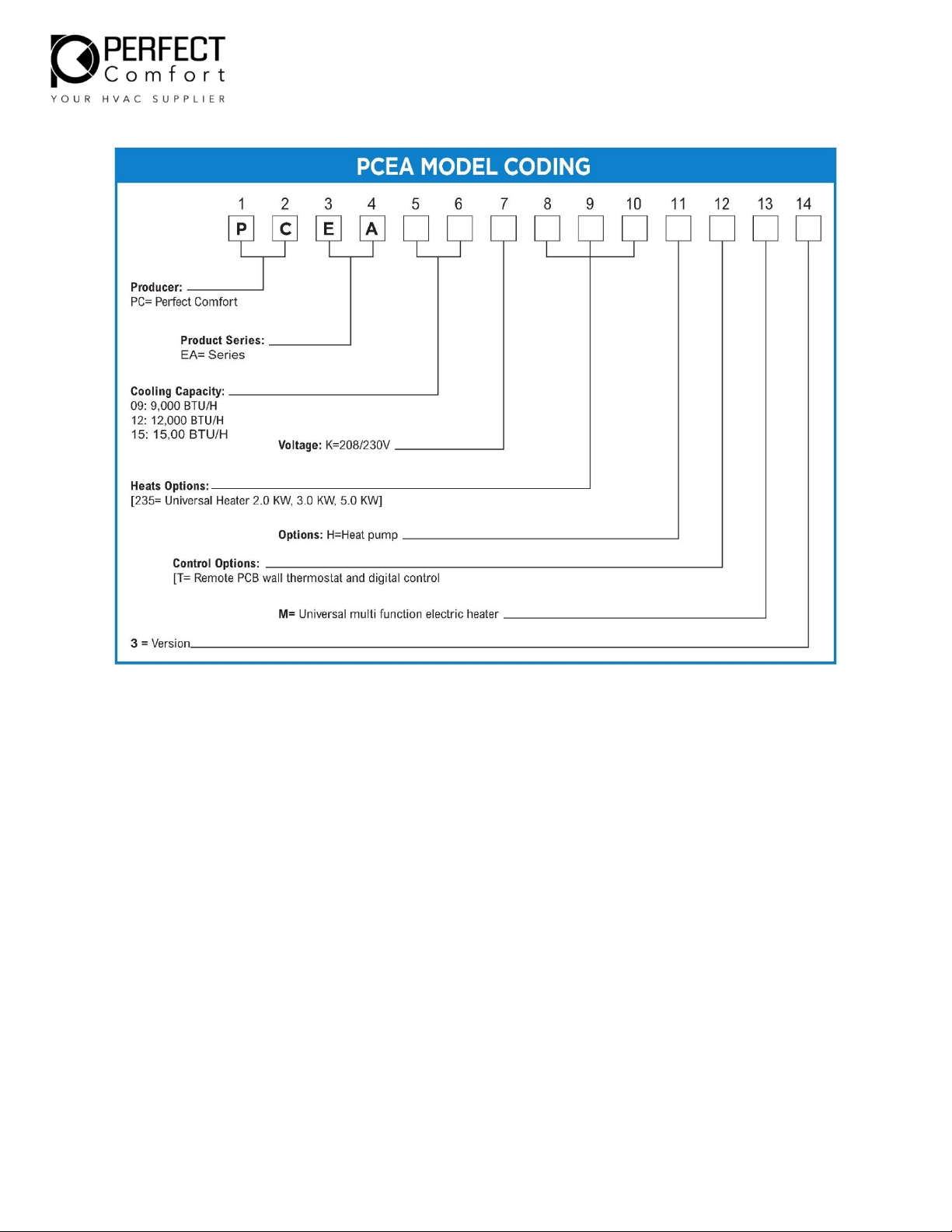
Product Description
Perfect Comfort replacement package terminal air conditioners have a cooling chassis with electric heat.
The PERFECT COMFORT PTAC unit
1. Use R410A refrigerant. This refrigerant is not affected by a phase out schedule. R410 is
environment friendly.
2. Include high-efficiency rotary compressors protected by a 6-year warranty
3. Offer three speed for evaporator fan motor, and one speed for condenser fan motor
4. Condensate removal system with dual drain hose, re- evaporation to improve efficiency
5. Heat Pump efficient operation
6. Digital control with optional thermostat hookup
7. Universal electric heat
2.0 KW heat can be obtained when 15A power cord is used at 230V. Part Number PC15UP.
3.0 KW heat can be obtained when 20A power cord is used at 230V. Part Number PC20UP.
5.0 KW heat can be obtained when 30A power cord is used at 230V. Part Number PC30UP.
PTAC units are available in nominal sizes of 9,000BTU, 12,000BTU or 15,000BTU
Standard control and components
Construction
1. 18 gauge galvanized steel and powder-coated for base pan and bulkhead, 20gauge
galvanized steel and powder-coat for construction.
2. Centrifugal evaporator fan with galvanized steel
3. Plastic fan blade for condenser
4. 20 gauge galvanized steel and powder coated for drain pan
5. Easily removable electric heater and easy access electrical box
6. Motors are thermally-protected.
7. Intelligent Control Board with digital control and optional thermostat control
(thermostat sold separately).
8. Washable filter
9. Metal protective discharge grille
Condensate removal system
1. Drain hose leads condensate to the outside base pan.
2. Slinger wheel, which is apart of the outdoor fan blade, throws condensate onto the
condenser coil during operation, where it evaporates, improving system performance.