PerfecTron ROC285B Series User manual

Version 1.0
Revision Date: Jul.22.2019
www.perfectron.com
ROC285B series
19” 1U Rack-mount
Intel® Q370 Rugged System
User’s Manual

Safety information
Electrical safety
To prevent electrical shock hazard, disconnect the power cable from the electrical outlet
before relocating the system.
When adding or removing devices to or from the system, ensure that the power cables for
the devices are unplugged before the signal cables are connected. If possible, disconnect all
power cables from the existing system before you add a device.
Before connecting or removing signal cables from the motherboard, ensure that all power
cables are unplugged.
Seek professional assistance before using an adapter or extension cord. These devices could
interrupt the grounding circuit.
Make sure that your power supply is set to the correct voltage in your area.
If you are not sure about the voltage of the electrical outlet you are using, contact your local
power company.
If the power supply is broken, do not try to fix it by yourself. Contact a qualified service
technician or your local distributor.
Operation safety
Before installing the motherboard and adding devices on it, carefully read all the manuals
that came with the package.
Before using the product, make sure all cables are correctly connected and the power cables
are not damaged. If you detect any damage, contact your dealer immediately.
To avoid short circuits, keep paper clips, screws, and staples away from connectors, slots,
sockets and circuitry.
Avoid dust, humidity, and temperature extremes. Do not place the product in any area
where it may become wet.
Place the product on a stable surface.
If you encounter any technical problems with the product, contact your local distributor
Statement
All rights reserved. No part of this publication may be reproduced in any form or by any
means, without prior written permission from the publisher.
All trademarks are the properties of the respective owners.
All product specifications are subject to change without prior notice

Revision History
Revision Date (yyyy/mm/dd) Changes
V1.0 2019/9/23 Initial release
Packing list
□19” 1U Rack-mount Intel® Q370 Fanless Rugged System
□Accessories
Item
Description Q’ty
1 Driver CD 1
2 Bracket Ear 2
3 Screw for fixing Bracket Ear M4 L:7.8mm 6
If any of the above items is damaged or missing, please contact your local distributor.
Ordering information
Model Number Description
ROC285B 1U Rackmount Fanless System with Intel® Q370, 3 x DisplayPort, 1
1 x PCIex16 slot, 90~264V AC-In, operating Temp -20 to 60°C
ROC285BB 1U Rackmount Fanless System with Intel® Q370, 3 x DisplayPort,
1 x PCIex16 slot, 90~264V Redundant AC-In, operating Temp -20 to 60°C

Table Contents
SAFETY INFORMATION ............................................................................................................................................. 1
ELECTRICAL SAFETY ....................................................................................................................................................... 1
OPERATION SAFETY ....................................................................................................................................................... 1
STATEMENT ................................................................................................................................................................. 1
REVISION HISTORY ................................................................................................................................................... 2
PACKING LIST ........................................................................................................................................................... 2
ORDERING INFORMATION ....................................................................................................................................... 2
TABLE CONTENTS ..................................................................................................................................................... 3
CHAPTER 1: PRODUCT INTRODUCTION .................................................................................................................... 4
1.1 KEY FEATURES ........................................................................................................................................................ 4
1.2 FRONT PANEL COMPONENTS ..................................................................................................................................... 5
1.3 REAR PANEL COMPONENTS ....................................................................................................................................... 5
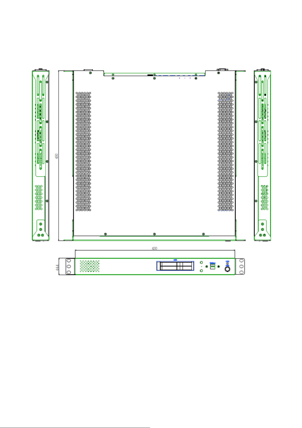
1.4 MECHANICAL DIMENSIONS ....................................................................................................................................... 6
CHAPTER 2: JUMPERS AND CONNECTORS ................................................................................................................ 7
2.1 CONNECTOR & LED PIN DEFINITIONS .......................................................................................................................... 7
LAN1 and LAN2 LED............................................................................................................................................. 7
AUDIO: LINE-OUT/MIC-IN .................................................................................................................................... 7
COM1: RS232/422/485........................................................................................................................................ 7
CHAPTER 3: GETTING STARTED ................................................................................................................................ 8
3.1 2.5" EASY SWAP SSD INSTALLATION ............................................................................................................................ 8
CHAPTER 4: AMI BIOS UTILITY ................................................................................................................................. 9
4.1 STARTING .............................................................................................................................................................. 9
4.2 NAVIGATION KEYS ................................................................................................................................................... 9
4.3 MAIN ................................................................................................................................................................ 10
4.4 ADVANCED .......................................................................................................................................................... 11
4.4.1 Trusted Computing ................................................................................................................................... 11
4.4.2 CPU Configuration .................................................................................................................................... 12
4.4.3 ACPI Setting .............................................................................................................................................. 13
4.4.4 Smart Setting ............................................................................................................................................ 13
4.4.5 F81866 Super IO Configuration ................................................................................................................. 14
4.4.6 Hardware Monitor .................................................................................................................................... 15
4.4.7 Platform Function ..................................................................................................................................... 16
4.4.8 Serial Consolr Redirection ......................................................................................................................... 17
4.4.9 NVMe Configuration ................................................................................................................................. 18
4.4.10 USB Configuration................................................................................................................................... 18
4.4.11 CSM Configuration .................................................................................................................................. 19
4.4.12 SATA Configuration ................................................................................................................................. 19
4.5 CHIPSET MENU .................................................................................................................................................... 20
4.5.1 System Agent (SA) Configuration ............................................................................................................... 20
4.5.2 PCH-IO Configuration ................................................................................................................................ 23
4.6 SECURITY MENU ................................................................................................................................................... 27
4.7 BOOT MENU ....................................................................................................................................................... 28
4.8 SAVE & EXIT ........................................................................................................................................................ 29

Chapter 1: Product Introduction
1.1 Key Features
System
CPU Type Intel® 14nm Coffee Lake-S Processor (Desktop) socket (LGA1151)
Core™ i7-8700T 2.4 GHz (12M Cache, 25W)
Core™ i5-8500T 2.1 GHz (9M Cache, 25W)
Core™ i3-8100T 3.1 GHz (6M Cache, 25W)
Chipset Intel® Q370
Memory Type 2 x SO-DIMM DDR4 2133/2400 MHz up to 64 GB
Expansion Slot 1 x Mini PCIe
1 x M.2 (Key E, 2230)with PCIex1 and USB2.0
1 x M.2 (Key M, 2242/2260/2280) with PCIex4 and SATA3 for SSD
Storage Device 2 x 2.5" Easy Swap SSD
Front I/O
Power Button 1 x (with LED indicator)
HDD LED 1
2.5" HDD/SSD Tray 2
USB 2 x USB 2.0
Rear I/O
COM 1 x RS232
DisplayPort 3 x DisplayPort (Max resolution up to 4096x2304@60Hz)
Ethernet 2 x RJ45
USB 4 x USB 3.0
Audio Mic-in, Line-out
AC-in 1 x IEC C14 Inlet
Mechanical & Environment
Power
Requirements
90V to 264V AC-in (Max Power Consumption: 200W)
ROC285B: AC-In
ROC285BB: AC-in w/Redundant
Dimension
(W x H x D)
430 x 44.4 x 450mm
(16.9” x 1.75” x 17.71”)
Operating Temp.
(ambient with air flow)
-20 to 60°C
Note: w/o any PCIe add-on card
Storage Temp. -20 to 70°C
Relative Humidity 5% to 95%, non-condensing
Compliance CE, FCC
*Specifications are subject to change without notice*

1.2 Front Panel Components
1 Power Button w/LED
2 USB 2.0 x 2
3 2.5” HDD tray x 2
4 HDD LED
1.3 Rear Panel Components
1 COM1: RS232
2 USB 3.1 x 4
3 DisplayPort x 3
4 LAN1 (Intel® I210)
5 LAN2 (Intel® I219LM)
6 Audio jack (Mic-in, Line-out)
7 PCIex16 Expansion Slot
8 IEC C14 Inlet, 90V to 264V AC-in

1.4 Mechanical Dimensions

Chapter 2: Jumpers and Connectors
2.1 Connector & LED Pin Definitions
LAN1 and LAN2 LED
AUDIO: LINE-OUT/MIC-IN
Pin
Definition
1 Line-out
2 Mic-in
COM1: RS232
Pin
RS-232
1 DCD-
2 RXD
3 TXD
4 DTR-
5 GND
6 DSR-
7 RTS-
8 CTS-
9 PWR (5V)

Chapter 3: Getting Started
This chapter provides more detailed information and let you know how to install components into
the ROC285B series embedded System.
Prior to removing the chassis cover, make sure the unit’s power is off and disconnected
from the power sources to prevent electric shock or system damage.
3.1 2.5" Easy Swap SSD installation
ROC285B series supports two 2.5" Easy Swap SSD
• Use Tri-angle security key to open keylock and pull out the 2.5” HDD tray.
• Put 2.5” SSD/HDD on the tray and make sure SSD/HDD is fixed and push the tray back.
• Use Tri-angle security key to lock the tray door.

Chapter 4: AMI BIOS UTILITY
This chapter provides users with detailed descriptions on how to set up a basic system configuration
through the AMI BIOS setup utility.
4.1 Starting
To enter the setup screens, perform the following steps:
Turn on the computer and press the <Del> key immediately.
After the <Del> key is pressed, the main BIOS setup menu displays. Other setup screens can be
accessed from the main BIOS setup menu, such as the Chipset and Power menus.
4.2 Navigation Keys
The BIOS setup/utility uses a key-based navigation system called hot keys. Most of the BIOS setup
utility hot keys can be used at any time during the setup navigation process.
Some of the hot keys are <F1>, <F10>, <Enter>, <ESC>, and <Arrow> keys.
Some of the navigation keys may differ from one screen to another.
Left/Right The Left and Right <Arrow> keys moves the cursor to select a menu.
Up/Down The Up and Down <Arrow> keys moves the cursor to select a setup
screen or sub-screen.
+− Plus/Minus
The Plus and Minus <Arrow> keys changes the field value of a
particular setup setting.
Tab The <Tab> key selects the setup fields.
F1 The <F1> key displays the General Help screen.
F10 The <F10> key saves any changes made and exits the BIOS setup
utility.
Esc The <Esc> key discards any changes made and exits the BIOS setup
utility.
Enter The <Enter> key displays a sub-screen or changes a selected or
highlighted option in each menu.

4.3 Main
The Main menu is the first screen that you will see when you enter the BIOS Setup Utility.
System Date
Use this function to change the system date.
Select System Date using the Up and Down <Arrow> keys. Enter the new values through the
keyboard. Press the Left and Right <Arrow> keys to move between fields.
The date setting must be entered in MM/DD/YY format.
System Time
Use this function to change the system time.
Select System Time using the Up and Down <Arrow> keys. Enter the new values through the
keyboard. Press the Left and Right <Arrow> keys to move between fields.
The time setting is entered in HH:MM:SS format.
Note: The time is in 24-hour format. For example, 5:30 A.M. appears as 05:30:00, and 5:30 P.M. as
17:30:00.
Access Level
Display the access level of the current user in the BIOS.

4.4 Advanced
The Advanced Menu allows you to configure your system for basic operation. Some entries are
defaults required by the system board, while others, if enabled, will improve the performance of
your system or let you set some features according to your preference. Setting incorrect field values
may cause the system to malfunction.
4.4.1 Trusted Computing
]

4.4.2 CPU Configuration

4.4.3 ACPI Setting
4.4.4 Smart Setting

4.4.5 F81866 Super IO Configuration

4.4.6 Hardware Monitor
4.4.6.1 Smart Fan Mode Configuration

4.4.7 Platform Function

4.4.8 Serial Consolr Redirection

4.4.9 NVMe Configuration
4.4.10 USB Configuration

4.4.11 CSM Configuration
4.4.12 SATA Configuration
This manual suits for next models
2
Table of contents
Other PerfecTron Industrial PC manuals