INSTALLATION INSTRUCTIONS
-05- -06--04-
TO TEST OCCUPANCY SENSORS
DIP SWITCH SETTING
TROUBLESHOOTING
WARRANTY INFORMATION
The sensors are factory preset to allow for quick installation in most applications. Verification
of proper wiring or coverage, or customizing the sensor's settings can be done using the
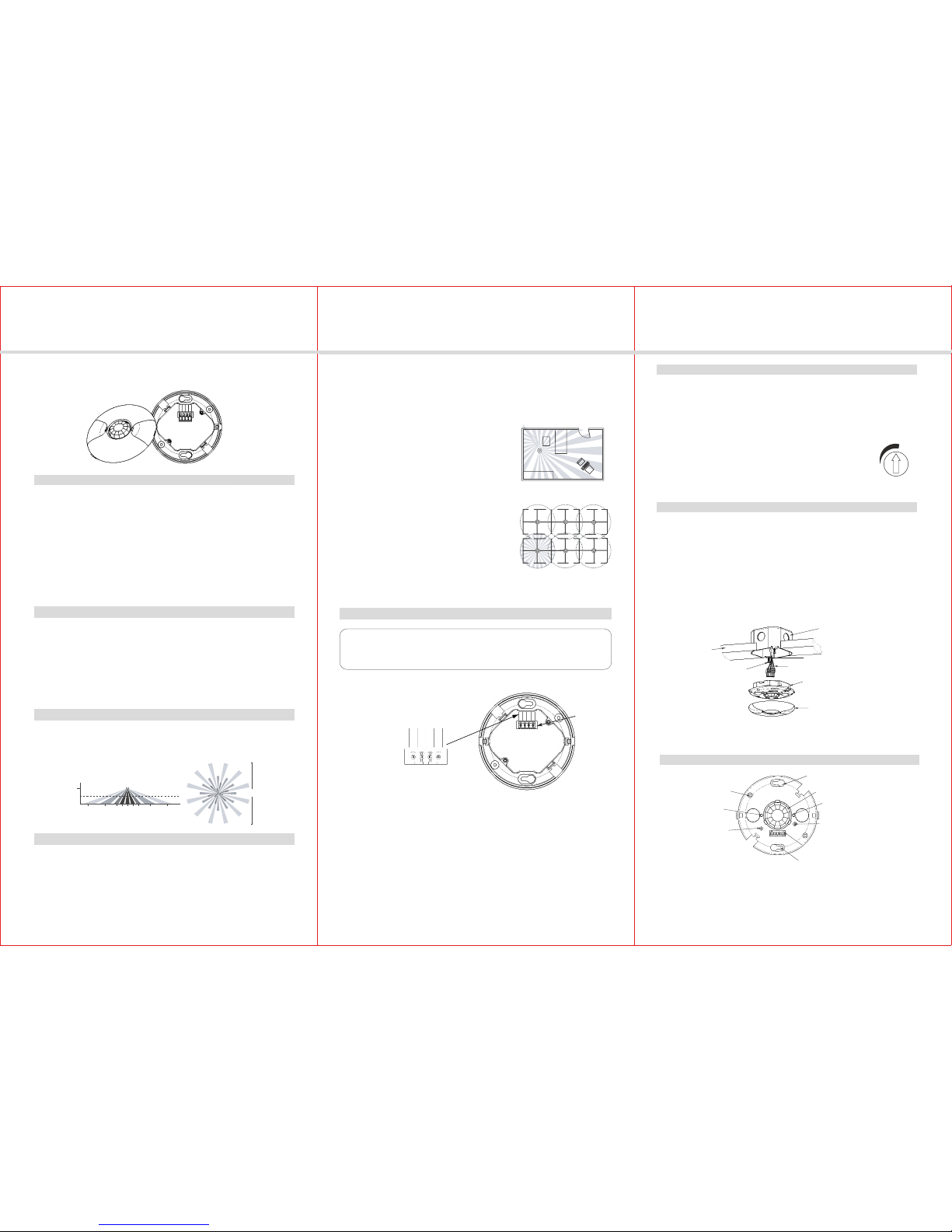
following procedures. To make adjustments, open the Front Cover with a small screwdriver.
There is a 40-second warm-up period when power is first applied.
Before making adjustments, make sure the office furniture is installed, lighting circuits are
turned on, and the HVAC systems are in the overridden/on position. VAV systems should be
set to their highest airflow. Set the DIP switches to the desired settings. See “DIP Switch
Setting”.
2. Ensure the Time Delay is set for Test Mode* using the “5 seconds/Autoset” setting.
1. Ensure the PIR Activity is enabled, red LED flashes, Hold ON mode are OFF (DIP 9 switch
OFF) and PIR Sensitivity is set to MAX (DIP switch 1 ON).
(DIP switches 2, 3 & 4 are OFF).
3. Ensure that the Light Level is at default (maximum). See the Light Level Feature section of
this document for instructions.
4. Remain still. The red LED should not flash. The green LED and load are ON, and the lights
should turn off after 5 seconds. (If not, see “Troubleshooting.”)
5. Move about the coverage area. The lights should come on.
When testing and adjustment is complete, reset DIP Switches and Light Level to the desired
settings, and replace the cover on the sensor.
* If you need to invoke the Test Mode and the DIP switches are already set for 5 seconds/
Autoset, toggle DIP switch #3 ON then back to the OFF position. This provides a 5 minute
test period. During the test period, the Time Delay is only 5 seconds.
Sensitivity Setting: Switch 1
50% , sensor's coverage is smaller, just about half of the widest range.
100% ,
the maximum range of sensor's coverage is 1200 square feet, see "coverage pattern".
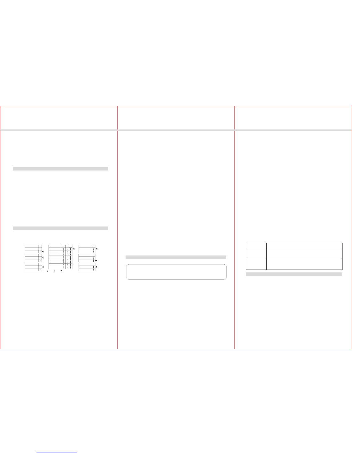
The PS-P24-CM has 9 DIP switches under the cover. They are used to set sensitivity,
time delay, walk through mode, vacancy mode, audible, visual alarm and Hold ON feature settings.
Sensitivity
50%
100%
Walk Through
Disabled
Enabled
Vacancy
Disabled
Enabled
Time Delay
5 Sec/Autoset
30 Seconds
5 Minutes
10 Minutes
15 Minutes
20 Minutes
25 Minutes
30 Minutes
Audible Alert
Disabled
Enabled
Visible Alert
Disabled
Enabled
Hold ON
Disabled
Enabled
1
5
6
7
8
9
234
=OFF =ON =Factory Setting
sensor will turn the lights off. The sensor can select the time delay using Autoset, or you can
Time Delay: Switches 2, 3, 4
The sensor will hold the lights on as long as occupancy is detected. The time delay countdown
starts when no motion is detected. After no motion is detected for the length of the time delay, the
select a fixed time delay.
Autoset records occupancy patterns and uses this history to choose an optimal time delay from
5s to 30 minutes. AutoSet behavior starts immediately and is refined continually as history is
collected.
Walk Through Mode: Switch 5
Turns the lights off three minutes after the area is initially occupied, if no motion is detected after
the first 30 seconds. If motion continues beyond the first 30 seconds, the selected time delay
applies. Only when a fixed delay is set greater than or equal to 5-minute the walk mode is effective.
Vacancy Mode: Switch 6
Manual on function is achieved by using a momentary switch. The switch connected to the sensor's
"Manual ON" and "Common". Each time the switch is pressed, the load will be reverted. The operation
of the sensor connected to manual switch depends on the DIP switch 6 setting.
Vacancy ON: In this mode, press the momentary switch again to turn on the load based on the
occupancy. This effective occupancy holds the load ON. After the time delay ends the manual
switch must be used to turn the load on, if there is no movement detected within the 30 second
period.
Automatic On: This mode, which is Vacancy Feature, uses occupancy to turn the load ON. A
manual switch provides the following additional functionality:
a. The load can be turned ON by manual switch activation and it stays on as long as occupancy is
detected. The sensor time delay operates as programmed. When the load turns OFF due to lack
of occupancy detection, the load can be turned ON again by occupancy detection or switch
activation.
b. Activating the manual switch while the load is ON turns the load OFF.
When the load is turned OFF manually, as long as the sensor continues to detect occupancy the
load stays OFF. Five minutes after the last occupancy detection, the lights stay off and the sensor
reverts to the automatic-on mode.
When the load is turned OFF manually, pressing the switch again turns the load ON and the
sensor reverts to the automatic-on mode.
Once the sensor returns to automatic-on mode, either the switch or occupancy detection can
turn the load ON.
Audible Alert: Switch 7
When this feature is turned on, 1 minute, 30 seconds, or 10 seconds before the time delay expires
you can hear "tick" from the buzzer, indicate that time delay is over.
Visible Alert: Switch 8
When this feature is turned on,1 minute delay before the time delay expires the load will flash
once to remind.
Hold ON: Switch 9
To override all sensor functions, set DIP switch 9 to the ON position. The green LED, red LED will
come on and stay on for the duration of the override.
This bypasses the light level, occupancy detection, and the manual ON functions will be invalid,
only to hold the load ON.
Lights do not turn on with occupancy, and the following condition exists:
PIR Activity LED does not flash:
NOTE: When power is initially applied to the sensor, there is a warm-up period of up to 40 seconds
before the LED is active.
CAUTION!
TURN POWER OFF AT THE CIRCUIT BREAKER BEFORE WORKING
WITH OR NEAR HIGH VOLTAGE.
2. Make sure that the PIR Sensitivity is set for Max/Autoset (DIP switch 1 ON ).
1. Check that the circuit breaker has been turned back on.
3. Check all sensor and power pack wire connections.
4. Check for 24V input to the sensor.
- If 24V is present, replace the sensor.
- If 24V is not present, check that high voltage is present to power pack. If it is, replace
power pack.
PIR Activity LED flashes:
1. If the sensor's Light Level has been turned to “ + ”, the lights connected to the Light Level
Output might be held off because of the level of ambient light in the controlled area. To test
whether the Light Level adjustment is the problem, cover the PIR lens and PIR Activity LED
(see diagram) with your hand to see if the lights turn on. If the lights turn on, the Light Level
setting was keeping the lights off (see, “Sensor Adjustment” for readjustment).
2. Check all sensor and power pack wire connections.
3. Check for 24VDC at the power pack's blue wire connection to sensor while sensor is activated.
If there is no voltage, replace the sensor. If there is voltage, replace the power pack.
Lights do not turn off automatically:
1. The sensor may be experiencing activations from outside the controlled area or from some
type of interference (see ”Unwanted Sensor Activations” below).
2. Check all sensor and power pack wire connections.
3. Disconnect power pack's blue wire:
If the lights do not turn off, replace power pack. Reconnect blue wire.
If the lights turn off, the problem may be in the sensor-to check:
Reconnect the blue wire.
Turn sensitivity and time delay to minimum and allow the sensor to time out.
If the lights turn off, the sensor is working properly (see “Sensor Adjustment” for readjust-
ment of sensor).
Unwanted Sensor Activations (LED flashes):
Possible causes
1. The PIR sensitivity may be set too high.
2. Sensor located too close to HVAC or VAV vents with heavy air flow.
Possible solutions
1. Set DIP switch 1 to OFF and ordering information see if the excess activations stop.
2. Relocate the sensor.
Power pack: 120/277VAC, 50/60Hz, 150mA, 20A ballast or
incandescent, 1HP@120/240VAC
PS-P24-CM
PS-PP3000
PIR Occupancy Sensor, low voltage,
sensor, up to 1200 square feet
Model Description
ORDERING INFORMATION
PerfectSense warrants to the original consumer purchaser and not for the benefit of anyone
else that this product at the time of its sale by PerfectSense is free of defects in materials and
workmanship under normal and proper use for five years from the purchase date.
PerfectSense’s only obligation is to correct such defects by repair or replacement, at its
option, if within such five year period the product is returned prepaid, with proof of purchase
date, and a description of the problem to PerfectSense Technologies LLC., Attn: Quality
Assurance Department 7877 College Road Suite #105, Baxter MN 56425. This warranty
excludes and there disclaimed liability for labor for removal of this product or reinstallation.
This warranty is void if this product is installed improperly or in an improper environment,
overloaded, misused, opened, abused, or altered in any manner, or is not used under normal
operating conditions or not in accordance with any labels or instructions. There are no other
or implied warranties of any kind, including merchantability and fitness for a particular
purpose, but if any implied warranty is required by the applicable jurisdiction, the duration of
any such implied warranty, including merchantability and fitness for a particular purpose, is
limited to five years. PerfectSense is not liable for incidental, indirect, special, or
consequential damages, including without limitation, damage to, or loss of use of, any
equipment, lost sales or profits or delay or failure to perform this warranty obligation. The
remedies provided herein are the exclusive remedies under this warranty, whether based on
contract, tort or otherwise.
August 2015