Perlick NS Series User manual

INSTALLATION AND OPERATION INSTRUCTIONS
CUSTOM NARROW DOOR BACK BAR CABINETS — SELF CONTAINED
Table of Contents
PREPARING THE CABINET
Specifications ........................................................2
List of Included Parts.............................................3
Tools Required ......................................................3
Plumbing................................................................3
Electrical................................................................3
Uncrating and Inspection.......................................3
Placing the Cabinet ...............................................3
Leveling the Cabinet..............................................3
Installing Casters or Legs .....................................3
Installing the Base Plate........................................3
Refrigeration and Temperature Control.................4
Cleaning the Cabinet.............................................4
Replacement Parts................................................5
Cleaning Stainless Steel .......................................6
Wiring Diagram......................................................7
8300 West Good Hope Road • Milwaukee, WI 53223 • Phone 414-353-7060 • Fax 414-353-7069
MODEL NOS.
NS Series
IMPORTANT INFORMATION
To register your product, visit our web site at
(www.perlick.com). Click on “Commercial”, then
“Service”. You will see the link to “Warranty
Registration Form”. You must complete and submit
this form or the installation date will revert back to
the ship Date.
This manual has been prepared to assist you in the
installation of your Cabinet and to acquaint you with
its operation and maintenance.
We dedicate considerable time to ensure that our
products provide the highest level of customer
satisfaction. If service is required, your dealer can
provide you with a list of qualified service agents. For
your own protection, never return merchandise for
credit without our approval.
We thank you for selecting a Perlick product and
assure you of our continuing interest in your
satisfaction.
WARNING: When lifting, the full weight of the
cabinet must be supported. Lift from the cabinet
base and not from the top. Improper lifting can
result in severe damage to the cabinet.
NS52 NS72
Form No. Z2285
Rev. 01.04.09

2
Perlick is committed to continuous improvement. Therefore, we reserve the right to change specifications without prior notice.
Sizes and Specifications
Custom Self-Contained Narrow Door Back Bar Cabinets
Form No. Z2285
Rev. 01.04.09
MODEL NOS. NS52* NS72
NUMBER OF DOORS 2 Door 3 Door
CABINET Length 52” (1321) 72” (1829)
DIMENSIONS Depth 243/4” (629) 243/4” (629)
(mm) Height 341/2” (876) 341/2” (876)
CASE CAPACITY (based on 12oz. Long Neck bottle) 12 18
CONDENSING UNIT H.P. 1/4 1/3
RUNNING LOAD –AMPS 5.5 8.1
SHIP WT. Lbs. (kg.) 340 (155) 430 (195)
INTERIOR Door pan and ceiling: High strength polystyrene. Floor pan and walls: Stainless steel. Includes pilasters,
(2) vinyl coated shelves and floor rack per door, and interior lights.
EXTERIOR Front, back, top and sides stainless steel. Bottom galvanized steel. See optional accessories for door &
grille finishes.
DOOR HINGING Stainless steel hinges with standard locations as illustrated. For special hinging specify
hinge locations starting from left to right. Field reversible.
DOOR HARDWARE Door handles: Choice of full length stainless steel, classic 6” black vinyl wrapped pull or top mounted
stainless steel pull tab. Lock finish: chrome
REFRIGERATION R-134a capillary tube-type. Aluminum fin and copper tube evaporator, epoxy coated coil. Adjustable
temperature control. Self-defrosting. Pull-out condensing unit for service and cleaning.
Compressor left, standard.
ELECTRICAL 115V, 60Hz., 1 phase AC. Furnished with 3-prong, 6 foot NEMA5-15 PC cord. Contact Perlick for other
voltage/frequency requirements.
PLUMBING Evaporator condensate is removed automatically. Optional floor drain with 3/4” NPT at right end or 1” NPS
out bottom come plugged from factory.
INSULATION Foamed-in-place polyurethane, 2” walls, 11/2” top.
OPTIONAL
ACCESSORIES &
MODIFICATIONS
34 1/2”
[876]
R19 1/2”
19 1/2”
[495]
DOOR
15 7/8”
[403]
DOOR
OPENING
4 1/4”
[107]
6 5/16”
[161]
12”
[305]
18 3/4” [476]
BACK LINER
TO INSIDE OF
DOOR SILL
NOTE “A”: 3/4” NPT DRAIN EXIT
NOTE “B” 1” DRAIN ACCESS
24 3/4”
[629]
31 1/4”
[794]
DOOR
HEIGHT 27 7/16”
[697]
DOOR
OPENING
7 3/4”
[197]
1 1/8”
[29]
“NOTE A”
“NOTE B”
56” [1422] 3 DOOR
36” [914] 2 DOOR
72” [1829] 3 DOOR
52” [1321] 2 DOOR
4 3/16”
[106]
22 3/4”
[578]
* Energy Star approved (solid door only). NOTE: This equipment is intended for the storage and display of non-potentially-hazardous bottled or canned products only.
• Leg set
• Compressor right
• Brass hardware
(classic & full length only)
• Caster sets
• Base plates
Door finishes
Black vinyl coated
Stainless steel
Painted in color of choice
Glass door with black vinyl
coated frame
Glass door with stainless
steel frame
Grille finishes
Black vinyl coated
Stainless steel
Painted in color of choice

3
Perlick is committed to continuous improvement. Therefore, we reserve the right to change specifications without prior notice.
Form No. Z2285
Rev. 01.04.09
General Information – Narrow Door Back Bar Cabinets
Parts List
■ (3) Shelves Per Door. (One may be used as a
floor rack).
■Door lock keys.
■ Shelf Clips.
Tools Required
■ #2 Phillips Screwdriver.
■ 3/8” Nut driver.
■ Power Drill or Driver (for leg installation).
Plumbing
Evaporator condensation is plumbed to a pan above
the compressor and evaporates automatically. An
interior floor drain is provided and can be plumbed
out the side (3/4” NPT), or out the bottom (1” NPS).
Electrical
The cabinet must be connected to a separately
fused power source (see electrical specification
plate) and grounded in accordance with National
and Local Electrical Codes. Caution: Do not
attempt to operate the equipment on any other
power source than that listed on the Electrical
Specification plate.
Uncrating and Inspection
Remove all crating material before operating.
Carefully inspect cabinet for hidden damage. If
damage is discovered, file your claim immediately
with the transportation company. Perlick is
not responsible for damage in transit.
Placing the Cabinet
Push the cabinet into place using rollers when
necessary. Important: Proper air flow around the
condensing unit is necessary for efficient operation.
Never obstruct the air flow in and out of the
condensing unit compartment.
Leveling the Cabinet
When the cabinet is in place, check installation with
a carpenter’s level. When perfectly level,
accumulated water will drain out. A slight pitch to
the drain side will not harm the cabinet. Water
may accumulate if cabinet is pitched to the
opposite side.
Installing Casters or Legs (Optional)
Attach casters or legs to cabinet bottom in holes
provided. Use the supplied 1/4”- 20 x 3/4”
hex head self-tapping machine screws.
Installing Base Plate (Optional)
Attach brackets and legs to cabinet bottom in holes
provided. Use the supplied 1/4”-20 x 3/4” hex head
self-tapping machine screws. Attach base plate
to brackets with the 1/4”-20 x 1/2” thumb screws
provided.
NOTE: A leg set kit must be used in conjunction
with base plates.

4
Perlick is committed to continuous improvement. Therefore, we reserve the right to change specifications without prior notice.
Form No. Z2285
Rev. 01.04.09
Preparing the Cabinet for Use – Narrow Door Back Bar Cabinets
Refrigeration andTemperature Control
The Back Bar Cabinet is equipped with a heavy-
duty refrigeration system designed to automatically
maintain a storage temperature of approximately 38
degrees F.
To Adjust the Temperature:
The temperature control is inside the cabinet on
the right-hand side of the evaporator fan panel
assembly. You will need a screwdriver to turn the
adjusting screw. Make small adjustments until the
desired temperature is achieved.
■ Colder Temperatures: Turn the adjusting screw
clockwise (to the right)
■ Warmer Temperatures: Turn the adjusting
screw counterclockwise (to the left.)
The condenser fan motor turns off and on with the
condensing unit. The evaporator fan motor runs
continuously. The fan motors are lifetime lubricated
and will require no oiling.
NOTE: Cabinet temperatures lower than 34° will not
allow for proper defrosting of the evaporator coil. If
defrosting is necessary, turn the control knob to the
OFF position until coil is defrosted.
Cleaning the Cabinet:
■ Disconnect all power prior to cleaning.
■ Use a mild detergent and water to clean the
inside and outside of the cabinet.
■ Inspect and clean the fan, evaporator coil and
light channel areas as necessary.
■ Dry thoroughly.
CAUTION: Never use a scouring pad or abrasive
cleaners.
Cleaning the Condenser:
Use a stiff brush to clean the dirt from the front
surface of the condenser. Keeping the condenser
free from dust and dirt will ensure efficient
operation.
CAUTION: Do not bend the fins while brushing the
front of the condenser.

Replacement Parts – Narrow Door Back Bar Cabinets
5
Perlick is committed to continuous improvement. Therefore, we reserve the right to change specifications without prior notice.
Form No. Z2285
Rev. 01.04.09
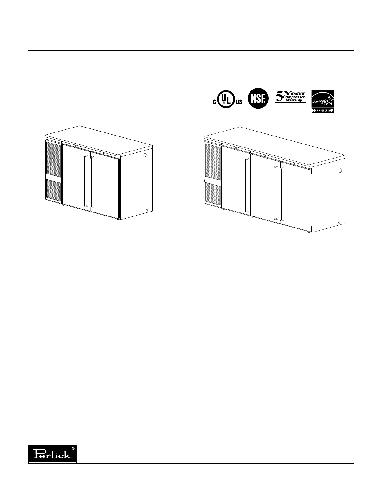
MODEL NOS. NS52 NS72
Condensing Units (BS Only)
Condensing unit 115 volt, 60 hz. C22647 C22646
Condensing unit 515301063 515301062
Compressor 513200314 513200003
Fan motor assembly 515315009 515315009
Condenser coil 15352019 15352019
Terminal board 519100088 519100088
Overload protector US-PB10HBX1 US-PB12HBX1
Relay US-PB10HBX1 US-PB12HBX1
Capacitor US-PB10HBX1 US-PB12HBX1
Evaproator Assembly
Self Contained (BS) complete 66308 65555-2
Evaporator coil (BS) &(BR) C17511-1EP C17511-2EP
Liquid & Suction line (BS) 65084 65085
Fan blade 57699 57699
Fan motor C15239A C15239A
Evaporator fan guard 65557 65557
Temperature control 61283 61283
Bulb clamp C6634 C6634
Wire harness, compressor bottom 65560 65560
Wire harness, evaporator 65561 65561
Wire harness, light jumper 65538 65539
Wire harness, mullion heater 65571 65572
Light bulb 63821 63821
Light bulb guard 65525 65525
Light socket 63484 63484
Light switch 65535 65535
Lock 63762 63762
Space, lock 63761-1 63761-1
Lock rail 65432-20SS or 65432-20 65432-20SS or 65432-20
Grille rail 65432-12SS or 65432-12 65432-12SS or 65432-12
Condenser pan 65565-1 65565-1
Condenser end panel 66215-1SS 66215-1SS
Grille, black 66210-12 66210-12
Grille, SS 66210-12SS 66210-12SS
Condenser housing back 65435-12SS 65435-12SS
Evaporator, liquid & suction line cover 65606L-1 or 65606R-1 65576-4L or 65576-4R
Evaporator pan 66311-1 65526-2
Door handle Several Options - Contact Factory
Door gasket 66237-5 66237-5
Cabinet hinge group left 66264L 66264L
Cabinet hinge group right 66264R 66264R
Hinge pin 63679-1 63679-1
End shelf kit - flat 66342-NE 66342-NE
Center shelf kit - flat — 66342-VM
Left or right shelf - flat 66355 66355
Center shelf - flat — 66356
End shelf kit - divided 66342-VE 66342-VE
Center shelf kit - divided — 66342-VM
Left or right shelf - divided 66398-1 66398-1
Center shelf - divided — 66399-1
Pilaster strip C19271-1 C19271-1
Shelf clip C15875 C15875
*Replacement door RD-NL2 RD-NL2
*Contact Perlick Milwaukee for complete door replacement. Cabinet serial no. required.

6
Perlick is committed to continuous improvement. Therefore, we reserve the right to change specifications without prior notice.
Form No. Z2285
Rev. 01.04.09
Cleaning Stainless Steel – Narrow Door Back Bar Cabinets
JOB CLEANING AGENT* COMMENTS
Routine Cleaning Soap, ammonia, detergent Apply with sponge or cloth.
Can be used on all finishes.
Fingerprints and smears Areal 20, Lac-O-Nu, Lumin Wash, Provides barrier film to minimize
O’Cedar Cream Polish fingerprints. Can be used on all finishes.
Stubborn stains and Allchem Concentrated Cleaner, Rub lightly, using dry or damp
Discolorations Samae, Twinkle, Zud Restoro, cloth in the direction of polish
Grade F or FFF Italian Pumice, lines on the stainless steel.
Whiting or Talc, Liquid Nu Steel,
Copper’s or Revere Stainless Steel
Cleaner, Lumin Cleaner, Sta-Clean,
Cameo Copper Cleaner, Allen Polish
Highlite, Penny-Brite, Copper Brite
* Use of propriety names is intended only to indicate a type of cleaner and does not constitute an endorsement.
Omission of any proprietary cleaner does not imply its inadequacy. All products should be used in strict accordance
with instructions on the package.
NOTE: Do Not Use Steel Wool or Scouring Pads to clean stainless steel.
Recommended Cleaning Agents

7
Perlick is committed to continuous improvement. Therefore, we reserve the right to change specifications without prior notice.
Form No. Z2285
Rev. 01.04.09
Reversing Door Hinge
Tools Required
■ #3 Phillips Screwdriver.
■ 1/16” Allen Wrench.
■ Flathead Screwdriver
Right Hinged Door
(as shipped from factory)
Operations to Perform on Cabinet
STEP 1:
Remove bottom hinge pin from
assembly.
STEP 2:
Carefully lift and tilt out door
assembly from the unit and
set aside.
STEP 3:
Remove lock rail from
cabinet, requires removal of
four screws.
STEP 4:
Remove top hinge pin.
Remove top and bottom
hinge brackets from the unit.
STEP 5:
Remove hinge bushing from
bottom hinge bracket and
assemble to top hinge bracket.
STEP 6:
Taking care not to scratch the
surface, remove hole plugs from
the left hinge holes.
STEP 7:
Insert hole plugs into vacant right
hinge holes.
STEP 8:
Re-assemble hinge brackets to unit. Bottom right bracket
is assembled as the top left bracket. Top right bracket is
assembled as the bottom left bracket.
STEP 9:
Re-insert top hinge pin.
STEP 10:
Re-assemble lock rail from
STEP #3
Operations to Perform on Door
STEP 11:
Remove bottom
door hinge bracket
from door assem-
bly and remove
door hinge bushing
from bracket.
Re-assemble door
hinge bracket to
previous position,
without bushing.
STEP 12:
Remove top door
hinge bracket from
door assembly and
assemble door
hinge bushing from
STEP 11 to bracket. Re-assemble door hinge bracket to
previous position with bushing attached.
STEP 13:
Door with full length SS handle:
There is no need to remove door handle. It will be
positioned correctly when door is reversed.
Door with SS pull tab or handle with wrap-
around bracket:
Remove the two screws mounting the handle and
reposition to appropriate location on the opposite
side of the door.
STEP 14:
Remove lock retainer and install on opposite end of door.
STEP 15:
What was the door top is now the door bottom. Carefully
lift the door onto the hinge brackets of the cabinet. The
two hinge bushings should meet. Reinsert the bottom
hinge pin to complete the door switching operation.
Step #12 Step #11 Step #13
Step #14
Step #6
Step #7
Remove
these screws
Top Hin
g
e Bracket
Bottom Hinge Bracket
Top Hinge Bracket
Bottom Hinge Bracket
Hin
g
e Bushin
g
65305-1
65189
65609-2
C31409-1
Not
Reversible
Handle Styles

Form No. Z2285
Rev. 01.04.09
8300 West Good Hope Road • Milwaukee, WI 53223 • Phone 414-353-7060 • Fax 414-353-7069
Perlick is committed to continuous improvement. Therefore, we reserve the right to change specifications without prior notice.
Wiring Diagram – Narrow Door Back Bar Cabinets
NS Series
This manual suits for next models
2
Table of contents
Other Perlick Indoor Furnishing manuals
Popular Indoor Furnishing manuals by other brands

Konig & Meyer
Konig & Meyer 13480 installation instructions

Walker Edison
Walker Edison W58FP18SM Assembly instructions

Rev-A-Shelf
Rev-A-Shelf 4PIL-18SC-2 installation instructions

Coaster
Coaster 800262 Assembly instructions

MAISONS DU MONDE
MAISONS DU MONDE HYPE 181324 quick start guide

Spencer
Spencer 402 user manual