PermaGreen Supreme CHEMmando Cavalry 60 A1B User manual

1
Perma-Green Supreme, Inc.
Turf CHEMmando Spray Equipment
Operator’s Manual
Cavalry Ride-on
Sprayer Spreader
table of contents
General Safety 2
Basic Operation 3
Sprayer Operation 4
Sprayer Calibration 5
Spreader Operation 6
Spreader Calibration 7
Adjustments 8
Maintenance 9
Maintenance Schedule 10
Transaxle Schematic 11
Transaxle Parts 12
Spreader and Starter Schematic 13
Pump & Wiring Schematic 14
Miscellaneous Parts, Misc 15,16,17
Introduction
This manual contains information on how to operate
the Cavalry Ride-on Sprayer/Spreader safely.
Please read it carefully before beginning operation.
If a problem should occur, or questions arise, please
consult Perma-Green Supreme, Inc.
All information in this publication is based on the
latest product information available at the time of
printing. Perma-Green Supreme, Inc. reserves the
right to make changes without notice and without
obligation.
This manual should be considered a permanent part
of the sprayer. Record the model number listed
below for ordering parts and when making technical
or warranty inquiries.
CAV 60 A1B
Direct all inquiries to:
Perma-Green Supreme, Inc.
5609 Murvihill Road
Valparaiso IN 46383
219-548-3801

A warning message alerts you to a potential hazard
that can hurt you or others. Each warning message
appears within a box like this.
WARNING!
A notice alerts you to potential hazards to your
equipment, other property, or the environment. Each
damage prevention message appears within a box like
NOTICE!
Careless operation or operator error can result in
serious bodily injury or property damage. The Cavalry
Ride-on Sprayer Spreader is only as safe as the
operator! Improper maintenance can cause injury. To
reduce the possibility of injury, read and follow all safety
instructions. Be certain that any new operator fully
understands and complies with the safety instructions
before operating the equipment.
WARNING!
Before Starting
1. Read this manual and familiarize yourself with all
the controls.
2. Practice getting on and off the machine and
operating the handle release, throttle, and brake.
3. Before starting the engine, refer to the Honda
owner’s manual for proper safety and operating
instructions.
4. Always inspect the lawn first. Mark any ridges,
ruts, holes, etc. and remove any debris or
objects that may interfere with the operation
of the Cavalry.
5. Plan your stragegy for treating the lawn prior to
beginning.
6. Before starting the engine, shift the transmission
into neutral.
To prevent loss of control and tipping
1. Operate only in daylight
2. Watch for holes or other hazards
3. Do not drive close to a drop off or other
hazard,
4. Reduce speed when making sharp turns
5. Do not operate in slippery conditions
6. Keep a firm hold on the handles
7. On hillsides, exercise extreme caution
a. Don not make sudden starts, stops or
turns
b. Do not go up and down hills
c. Treat slopes beginning at the bottom
d. Travel across the grade wherever
possible
e. Reduce speed
f. Operate as a walk behind whenever
necessary
g. Do not operate on slopes over 15
dergrees.
WARNING!
General Safety
1. Keep the hood in place. Replace it if it is
damaged.
2. Keep hands and loose clothing away from all belts
while the engine is running.
3. Wear proper clothing, shoes, and safety glasses.
4. Do not let children or untrained adults operate the
machine.
5. Do not run the engine in an enclosed area. Exhaust
fumes are hazardous and can kill.
6. When leaving the operating position, shift
transmission into neutral. Turn engine off, and if on
an incline, block the wheels.
7. Do not touch the hot engine or muffler.
8. If the equipment begins vibrating or making unusual
noises, stop immediately, check for the cause, and
repair.
SAFETY 2
Safety messages - Read Carefully

BASIC OPERATION 3
First 8 Hours of Break in
1. Test clutch disengagement. With transmission in
neutral and the motor running, check to see that the
transmission input pulley is not turning. Adjust belt
guide or clutch engagment if necessary
(see page 8).
2. Check and adjust belt tension every 2 hours during
the first day’s operation.
3. Check for loose hardware and tighten as needed.
4. Grease rear wheel bearings (2)
5. Lubricate the articulating rod ends (3) between the
sulky and spreader. Use WD 40, light oil, or coat with
grease.
6. Check tire inflation (approx. 15 psi). NOTE: All tires
are filled with diluted RV anitfreeze or water for
balast. Dispose of in sanitary sewer or septic tank or
according to local regulations.
Operating Instructions
1. Read and understand all the safety instructions prior
to attempting to operate the machine.
2. Before starting
A. Check the oil level
B. Fill thetank with 87 or higher octane gas
C. Open fuel valve
D. Shift transmission into neutral
3. Start Engine - choke as necessary by pushing and
holding the throttle lever forward. When started, slowly
pull the throttle back to the detent run position.
If the engine is warm, choking may not be necessary.
4. Shift into a low gear (reverse is farthest forward
followed by the neutral and 6 forward gears) and step
onto the sulky.
To avoid serious bodily injury and transmission
damage, the machine must be at a full stop before
shifting from reverse to forward or from forward to
WARNING!
HANDLE VIEW (Diagram 3-1)
A - Clutch 215520
B - Throttle 654120
C - Spreader on/off 432112
D - Pump Switch 344334
E - Handle Release Lever Rear Brakes
A - Brake Assembly
B - Peddle
C - Linkage Swivel
D - Return Spring
E - Articulating Joint
Gear Shift
5. To go forward, pull and hold the clutch lever.
6. To turn right, pull the right handle toward you.
Simultaneously shift your weight to the right side of the
machine. To turn left, pull the left handle bar toward
you and shift your weight to the left side of the
machine. (continued on page 4)

(continued from page 3)
7. To stop, release the clutch lever and step on the
brake pedal.
8. To back up, come to a complete stop, shift into
reverse, and pull the clutch lever.
9. To operate the machine as a walk behind, pull the
handle release lever and step backwards off the sulky.
Pull the handle down with you. NOTE: The handle
does not lock in a down position.
10. To return to a riding position, step up on the sulky,
pushing the handle forward until it locks in the up
position.
Sprayer Operation 4
Overview
Both 3 gallon tanks have common suction and return
flow lines and act as one tank. The 12 volt pump is
located under the hood. A generator driven by the
motor directly supplies the electricity to the pump.
The pump is turned on with a switch to spray and off
to stop spraying. A pressure unloader valve
automatically maintains a constant 10 psi, therefore a
constant flow. To facilitate spraying, several spray
widths can be selected with the two spray control
valves located above and between the spreader
hopper and tanks. The nozzles installed are sized to
apply the proper application rate when set to spray 9
feet, 4.5 feet, and 2.5 feet respectively.
Sprayer Operation
FRONT NOZZLES
A - broadcast nozzles 465220
B - 1/2 width (4.5’) nozzle 465128
465028C - trim (2.5’) nozzle
1 Fill tanks with water. Note both tanks are
connected together and act as one.
2 To spray up to 9 feet wide (full width broadcast),
point the handle of the right spray control valveto
SPRAY CONTROL VALVE SETTINGS
A - Broadcast = 9’ wide
B - Off
C - 1/2 Width = (4.5’)
D - Trim = (2.5’)
E - Off
F - Wand
F
the right and point the left spray control handle to
the rear. With the motor running, pull the spray
switch toggle toward the hand grip to momentarily
spray or push the toggle forward to spray
continuously.
3 To spray 4.5 feet wide (half width broadcast),
point the handle of the right spray control valve to
the left and the handle of the left spray control
valve to the rear. Operate the spray toggle switch
as before.
4 To spray 2.5 feet wide (trim width), point the
handle of the right spray control valve to the rear
and the handle of the left spray control valve to
the right. Operate the toggle switch as before.
5 To use the wand, point the handle of the right
spray control valve to the rear and the handle of
the left spray control valve to the left. Push the
toggle switch forward and use the wand like a
power back pack.

Sprayer Operation, Calibration 5
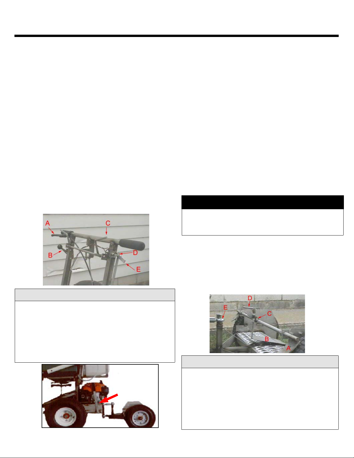
Adjusting the spray pattern
Broadcast Boom Nozzles
1) Rotate the 2 red turbo floodjet nozzles within the
red caps on the black nozzle bodies on the boom
until the spray pattern is generally forward with a
slight angle to the outside, so there is less overlap
in the center.
2) Rotate the entire nozzle body on the boom until
the spray comes out slightly less than parallel to
the ground and delivers the spray width desired.
(Up to a maximum of 9-10 feet).
Half Width Spray Nozzle (lower center
nozzle)
1) Rotate the blue extended range TJet nozzle within
the red cap until the spray pattern is level from
right to left.
2) Rotate the entire black nozzle body until the spray
pattern covers a distance that is about one half
the width of the broadcast spray boom.
Trim Nozzle (top center)
1) Rotate the green TJet nozzle within the red cap
until the spray pattern is level from right to left.
2) Rotate the entire nozzle body until the spray
pattern covers a distance of about the width of the
front of the machine.
Wand
1) Rotate the Tjet nozzle until the spray comes out at
an angle that is comfortable.
•Leaks may create a spray that can hurt you or the
environment. Use water to test the system for
leaks before adding chemicals.. Repair any leaks
immediately.
•Exposure to chemicals can cause serious bodily
injury or death. Always read and follow chemical
label directions and wear the safety equipment
mandated on the label.
•The spray may be difficult to see and be blown off
target by the wind. It is the operator’s
responsibility to apply chemicals in a safe manor.
WARNING!
Suggested Method of Spraying
& Spreading
Use a double overlap spread. Turn so that on the
next pass the fertilizer reaches approximately back
to the center of your last wheel marks.
*Refer to pages 6 and 7, for instructions
*Set the spread rate dial so that you apply 1/2 rate
with each pass.
*Follow the Accuway instructions to center or
equalize the spread pattern, and then:
1) Mark off a test course and fill tanks with water.
2) Measure the area. Ex:100’x100’=10,000 sq ft
3) Turn on your spray boom and adjust your spray
pattern to the desired width of spray.
4) Fill the tanks with water to a marked line (mark
both tanks)
5) Spray the test course at your normal speed and
with your normal overlap (determined by your
spreader settings).
6) Measure the ounces of water necessary to
refill the tanks to the marks (allow adequate
time for the tank level to equalize).
7) Divide the amount of water used by the number of
1,000 sq.ft. incriments in your test course inStep 2.
This equals your spray rate in ounces per 1000
sq ft. Locate that number in the left column of
the MIX CHART.
8) Repeat the test a number of times to insure
accuracy.
9) From your product label, find the recommended
rate of chemical to apply per 1000 sq ft. Locate
that number in the top line of the MIX CHART,
10) Read across from your spray rate number in
the left column until it intersects with your
chemical per 1000 sq ft column. That number
is the amount of chemical needed to mix 1 gallon
of spray solution.
EXAMPLE: Your calibrated spray rate is 16 oz. per
1,000 sq.ft. and your product label requires 1.5 oz. of
chemical per 1,000 sq.ft. You would need 12 oz.of
chemical to mix 1 gallon of solution.

To Spread
To avoid streaking the lawn, apply fertilizer at half rate
and spread back to approximately the center of your
wheel marks.
1) Set the rate dial and rate adjustment stop bolt (see
diagram) to the proper setting to deliver 1/2 the rate of
fertilizer with 1/2 the rate of fertilizer with each pass.
(see page 7)
2) Equalize or balance the spread pattern with the
Accuway control knob as described on page 7.
3) To begin spreading, pull the spreader control
lever towards you. You may use either hand.
4) To stop spreading push the spreader control
lever forwards.
Mix Chart/ Spreader Operation 6
SPRAY RATE .75 oz/1000 1.0 oz/1000 1.25 oz/1000 1.5 oz/1000
15 6.4 8.5 10.7 12.8
16 6 8 10 12
17 5.6 7.5 9.4 11.3
18 5.3 7.1 8.9 10.7
19 5.1 6.7 8.4 10
20 4.8 6.4 8 9.6
21 4.6 6.1 7.6 9.2
22 4.4 5.8 7.25 8.7
23 4.2 5.6 7 8.4
24 4 5.3 6.6 8
25 3.8 5.1 6.4 7.7
26 3.7 4.9 6.1 7.4
27 3.5 4.7 5.9 7.1
28 3.4 4.6 5.7 6.9
29 3.3 4.4 5.5 6.6
30 3.2 4.3 5.4 6.5
MIX CHART - ounces of chemical to make 1 gallon of spray solution
A B
Spread headers across
short ends (A and B) on
diagram. Then cover
ground as shown. SPREADER CONTROLS
A - on/off swivel nut 652510
B - control lever
C - on/off cable 05-98-0018
D - on/off sheath
E - Adjustment stop bolt
F - jamb nut
NOTICE!

Spreader Calibration 7

Clutch and Belt Adjustment 8
To avoid mis-application of product, streaking, or
other imperfection:
1) Calibrate the spreader regularly.
2) Equalize or balance the pattern regularly
3) Keep spinner blades clean.
4) Replace rotary agitator if worn or bent.
5) Keep spreader clean and dry and well
maintained (refer to page 10).
6) Test all products on non-valuable turf
prior to treating desirable turf.
7) Use a double overlap (spread back to
center) technique.
8) Never leave fertilizer in hopper -
NEVER! Empty hopper, clean, and grease
immediately after use.
9) Exercise extreme caution in windy
conditions.
NOTICE!
To avoid serious bodily injury, turn off motor and
remove the spark plug wire prior to performing any of
the maintenance described on this page.
WARNING!
To increase clutch engagement
Clutch Adjustment
A - Clutch cable ferrel
B - Jamb nut
1. Use a 12mm wrench to loosen the rear nut (B) on
the lower clutch cable ferrel (A in diagram below).
2. Tighten the forward nut to pull the clutch bell crank
arm (B) forward and tighten the rear nut.(B)
3. Test the clutch for proper operation and re-adjust
as necessary.
A. With the transaxle in neutral, start themotor.
B. Pull and release the clutch lever. NOTE:
The transaxle input pulley MUST stop turning when
the clutch lever is released (see belt guide
adjustment).
C. Shift into gear and test clutch operation.
Readjust as necessary.
Belt Guide Adjustment (see page 9)
The belt guide (C) in the diagram below helps
disengage the drive belt (D) from the motor pulley (E).
Improper adjustment will result in transmission
damage.
1. With the clutch lever guide pulled, there must be a
slight gap between the belt guide and the belt.
2. Release the clutch lever, the belt guide MUST
contact the belt and push it away from the motor drive
pulley.
To adjust:
1, With the clutch properly adjusted, loosen the bolt
holding the V belt idler pulley (F) to the bell crank
arm.
2. Pull and hold the clutch lever. Position the belt
guide so that there is a slight gap between the belt
guide and the belt. Tighten the idler pulley bolt.
3. Test and re-adjust as necessary.
Spinner Generator Belt Adjustment
1. Remove the belt by stretching it while manually
turning the pulley.
2. Using a wire cutter, cut a small section out of the
belt at the connector. NOTE: Do not damage the
connector.
3. Pull the excess off the connector and assemble the
belt and reinstall.
(see Warning, page 9)

Maintenance 9
Improper clutch and belt guide adjustment can result
in a dangerous run-on situation, premature belt wear
or transmission damage.
WARNING!
BELTS & PULLEYS (above)
A - clutch bell crank
B - Idler pulley, clutch 653610
C - clutch belt guide
D - motor drive belt 653670
E - Motor drive pulley 653550
E1 - Generator drive pulley 653542
F - generator belt 653701
G - Generator 653740
H - Idler pulley, flat drive belt 653620
I - Idler pulley, spinner 653430
654130J - clutch adjustment ferrel
FRONT END PULLEYS (preceeding column)
A - Spinner lower bearing block 652120
B - Spinner pulley 653530
C - Upper spinner belt 653780
D - Lower spinner belt 653790
E - Transmissionn input pulley 653400
F - Spinner Idler pulley 653720
G - Shifter rod
Check Oil Level
1. Locate unit on a level surface.
2. Remove hood.
3. Locate the rubber fill plug next to the shift rod as it
enters the transaxle cover.
4. With needle nose pliers or a neddle nose vise
grip, work under the lip of the plug, rocking from side
to side until the plug is removed (Illustration 1).
5. Insert diptick Part Number 35942. Insert the gauge
at a 45 degree angle. Check for
approximately 1/2 inch of oil when inserted. This is
16 ounces of EP90 gear oil (Illustration 2).
6. Reinstall the plug by lubricating it with WD40 oil or
spray lubricant. An installation tool can be made by
using a tool shown in Illustration 3.

MAINTENANCE 10
Break in Daily Weekly Monthly Scheduled Maintenance Procedure
X X Check engine oil level
X X Oil or grease articulating pivot joints
X Visual safety inspection of articulating joint area,
looking for loose bolts, bending, or cracking of welds
and metal braces
X X Check all hardware for tightness
X Grease rear wheel bearings
every 2 hrs X Check belt tension
1st 20 hrs every 50 hrs Change engine oil (increase frequency in dusty
conditions)
every 50 hrs Clean air filter (increase frequency in dusty
conditions)
X Lubricate spinner bearings
X Lubricate clutch bell crank pivot
every 300 hrs Clean and adjust spark plug
X Grease spinner idler pulley
X Oil Spinner shaft lower bearing block
X Grease handle drop down latch mechanism
Dry cleaning (prefered)
Use compressed air to remove fertilizer and residue from the machine. Then wipe with an oily rag. Pay particular
attention to components under the hood.
Wet cleaning
When water is used, blow dry the spreader completely. Pay particular attention to drying the components under
the hood and motor. NOTE: Good “dry cleaning” is preferable to a poor “wet cleaning”.
Keep the machine dry and clean. Fertilizer and water
form and acid solution which will corode the mild steel
and aluminum components such as the transaxle, motor
block, pulleys, and articulating joints.
NOTICE!
Revised 4/99

Transaxle Schematic 11

PEERLESS TRANSAXLE Model MST-206-511c 12
Ref. Part # Description Qty
1 772147 Transaxle cover 1
2 780086A Needle Bearing 5/8” 2
3 770128 Transaxle Case 1
4 776395 Countershaft 1
5 776409 Output Shaft 1
6 778364 Spur Gear (38 teeth) 1
6A 778369 Spur Gear (15 teeth) 1
7 778330 Spur Gear (11 teeth) 1
8 792180 Shift Key 2
8A 792047 Woodruff Key #9 1
9 784352 Shift Collar 1
10 784379 Shift Rod & Fork 1
11 778334 Bevel Gear (30 teeth) 1
12 778309 Input Bevel Pinion (13 teeth) 1
13 778368 Bevel Gear (13 teeth)(incl 14) 2
14 778368 Bevel Pinion (13 teeth)(incl 13) 2
15 778370 Ring Gear (43 teeth) 1
17 786188 Drive Pin 1
18 786102 Spacer 1.130 1
20 792077A Ball 5/16” Dia 1
21 792078 Set Screw 3/8-16x3/8” 1
22 792079 Spring 1
25 792073A Screw 1/4-20x1-1/4” 17
25A 792177 Screw 1/4-20x1-3/8” 2
26 792125 Retaining Ring (pkg of 2) 4
27 792035 Retaining Ring 1
28 788040 Retaining Ring 1
29 780072 Thrust Washer .627 ID 5
29A 780160 Thrust Washer .563 ID 1
29B 780051 Thrust Washer .762 ID 3
30 780108 Cup Washer 1.127 ID 5
31 780001 Washer (.056 wide) (Use as needed) 2
31A 780195 Flat Washer (.062 wide) 2
32 788083 Oil Seal 5/8” 1
34 780194 Bushing 9/16” ID 2
35 780193 Flanged Bushing 5/8” ID 2
35A 780197 Flanged Bushing 3/4” 2
Ref. Part # Description Qty
47 774943 Axle (12-7/16” long) 1
48 774837 Axle (17” long) 1
49 778356 Spur Gear (29 teeth) 1
50/83 778338 Spur Gear (27 teeth) 1
51 778354 Spur Gear (23 teeth) 1
52 778352 Spur Gear (19 teeth) 1
53 778350 Spur Gear (16 teeth) 1
54 778346 Spur Gear (15 teeth) 1
56 778355 Spur Gear (11 teeth) 1
57 778337 Spur Gear (13 teeth) 1
58 788353 Spur Gear (17 teeth) 1
59 778351 Spur Gear (21 teeth) 1
60 778349 Spur Gear (24 teeth) 1
61 778345 Spur Gear (25 teeth) 1
65 780189 Flat Washer .563 ID 1
66 776442 Input Shaft 1
67 776396 Shifter & Brake Shaft 1
69 792170 Retaining Ring 1
70 786187 Spacer .890 1
71 788069 Seal 1
71A 792162 1/2” Washer 1
71B 788092 “O” Ring .426 ID 1
76 780090 Flat Washer 1.128 ID 1
77 788078A Inverted Retaining Ring 1
79 792144 Spring 1
82 778333 Bevel & Spur Gear (30 & 13 teeth) 1
85 792154 Oil Fill Plug 1
87 788089A Oil Seal 9/16” 1
150 788093A Liquid Gasket RTV Silicone 1
157 788088A Oil Seal 3/4” 2
180 730229A Gear Oil 80W90 1

Spyker Hopper, Starter 13
1 Hopper, Plastic 05-94-0054-5
2 Cover 05-94-0058
3 Screen Holder 05-98-0019
4 Screen SS-96-0002
5 Adjustment Screw 05-94-0045
6 Jamb Nut 05-94-0087
7 Rate Gate SS-94-0003
8 Gate Guide 05-94-0042
9 Diffuser 05-94-0043
10 Gate Guide 05-94-0042
11 Dial Mount SS-97-0005
12 Dial SS-94-0006
13 1/4-20x1/2 Screw 99-10-0205
14 Rate Gate Linkage SS-94-0002
15 Rotary Agitator SS-96-0003
16 Spinner Cam 05-94-0019
17 Spinner SS-94-0012
18 Felt Washer SS-92-0002
19 Hopper Bearing SS-94-0007
20 Roll Pin 1/8x7/8 SS-90-0002
21 Spinner Shaft 05-97-0021
23 On/Off Cable 05-98-0018
24 Cable Jamb Nut 05-91-0009
Description # Part Number
1. Starter Assembly 1 28400-ZG9-802
2. Housing Assembly 1 28402-ZG9-802
3. Pulley/Spring Assy. 1 28415-ZG9-802
4. Pin, Center 1 28419-ZG9-802
5. Plate A, Friction 1 28431-ZG9-802
6. Plate B, Friction 1 28432-ZG9-802
7. Spring, Friction 1 28441-ZG9-802
8. Retainer 1 28444-ZG9-802
9. Handle 1 28461-ZE6-T02
10. Rope, Recoil Starter 1 28462-ZG9-802
11. Handle, Reinforc... 1 28463-ZE6-T02
12. Ratchet, Starter 2 28485-ZE6-T02
2 28486-ZE6-T0213. Spring, Dog

14
PLUMBING PARTS
A - 3 gal tank 204942
A1 - 3 gal tank lid 204943
B - in-tank strainer 451090
C - Pump 442072
D - QJ Nozzle cap 1/4 fpt 466446
E - QJ nozzle gasket 466626
F - 10 psi unloader 442427
G - Spray control valve, 3 way 480022
H - 1/4 tee 476022
I - QJ nozzle body, 8 psi 466441
J - 50 mesh strainer 464724
K - Nozzle, TF2VP 465220
L - QJ nozzle cap, red 466622
M - Boom arm, right 474321
N - Boom arm, left 474322
O - Nozzle, XR11003VS 465128
P - Nozzle, XR80015VS 465028
Q - Wand 372027
R - TJ nozzle cap 463819
S - 1/4 clear braid hose 363220
362210T - 3/8 id x 1/2 od tubing
WIRING
A - Pulley, Generator 653530
B - Bushing, Generator pulley 652024
C = Generator 653740
D - Quick connect plug
E - Quick connect plug
F - Jumper wire
G - Switch, SPDT mon..on/off/on 344324
H - Pump, cavalry 442070
I - Fuse holder 342430
342440J - Fuse, 7.5 amp mini

Tires
13/500x6 Tire, Rim, Hub
654620
13/500x6 2P TR
654810
13/500x6 Tube
654930
R64DN Rim 654680
417-5/8 BB Hub
654710
Plumbing
1/4mpt x 1/4 hose barb
452220
1/4fpt x 1/4 hose barb
454002
1/4hb x 3/8hb elbow 454016
3/8hb x 3/8hb elbow 456317
1/4mpt x 1/4hb elbow
454022
1/4mpt x 3/8hb elbow
454023
50 mesh strainer
464724
1/4 hose clamp
481238
3/8 hose clamp
481242
3 Gallon Tank
204942
3 Gallon Tank Lid
204943
Tank Strainer
451090
Spray Control 3 way Valve
480022
Nozzle Body, 8 psi 466441
Pressure Relief Valve
PARTS 15
Bearings, Pulleys, Belts
Articulating 3/4 Rod End-female
652470
Articulating 3/4 Rod end-male
652471
Spinner Pillow Block
652220
Spinner Idler Bushing
652120
1/4 Tie Rod End
652475
1/4 Urethane Belting
653700
1/4 Urethane Belting connector
653702
Generator Bushing 652022
Spinner Pulley Bushing
652038
Pulley, Spinner Idler assembley
653720
Pulley, Idler Bushing
652024
Pulley, Transaxle input
653730
Electrical
Generator 653740
Fuse, 7.5 amp mini 342440
SPST momentary on/off/on
Hardware
Spring, Brake Pull
654502
Spring, Return
654504
Brake Lever 654180
Clutch Lever 215520
Motor, 5.5hp Honda Vertical
449026
Cable, Clutch/Brake 654130
Grips, Foam 654190
Woodruff key, Motor shaft
651610
Cotter Pin 651600
5/8 Shaft Collar, sintered

Honda Engine Distributors 16

SUGGESTED CAVALRY PARTS INVENTORY PACKAGE
ONE EACH PER PACKAGE
PART # DESCRIPTION PRICE EA
653701 Generator Belt 5.30
653780 Upper Spinner Belt 6.95
653790 Lower Spinner Belt 7.95
653670 Drive V Belt 14.79
653610 Bell Crank V idler Pulley 8.75
653620 Flat idler Pulley 8.75
432112 Hopper Control Cable 12.00
654130 Clutch Cable 10.00
215520 Clutch Lever 13.00
465220 Turbo Floodjet Nozzle 1.94
466622 Nozzle Cap & Gasket 1.39
464724 50 Mesh Strainer .70
466441 Nozzle Body 8.37
449036 Honda Starter Kit 25.00
654148 Cable stop nut .50
654506 Link shift, square hole 3.00
432142 Spyker agitator wire 1.20
432128 Spyker diffuser 4.80
432122 Spyker Rate gate diff guide (2) 1.82 ea
432055 Spyker rate gate linkage .50
432052 Spyker dial mount 2.38
432054 Spyker dial, plastic 2.24
432057 Spyker jamb nut .76
432126 Spyker adjustment screw assy 5.84
TOTAL 129.99
17

Perma-Green Supreme Inc hereby warrants to the original purchaser that products
manufactured by Perma-Green Supreme Inc. will be free from defects in material and
workmanship FOR A PERIOD OF (1) ONE YEAR FROM THE DATE OF PURCHASE,
EXCEPT AS NOTED BELOW.
PROTECTION PLAN
The Company will provide the replacement parts found to be defective. Such replacement will be free of charge to the
purchaser for (1) one-year from the date of purchase.
This Warranty is subject to the following exceptions and limitations:
PURCHASER RESPONSIBILITIES
Maintenance & minor adjustments per owners manual
Notification of need for warranty service
Transportation to/from place of warranty repair
PURCHASED PARTS WARRANTY
90 Days on purchased components i.e., (any plastic and electrical components, wire harness, etc.)
30 Days on parts and normal wear items i.e., (belts and rubber components, bearings, cables, controls, clutches, etc.)
ENGINES, ENGINE ACCESSORIES, & PEERLESS PRODUCTS
Covered only by manufacturer's warranty
EXCLUSIONS
No warranty is extended to any equipment, which has been altered, misused, misassembled, improperly adjusted,
neglected, or damaged by accident.
No warranty is extended on any parts that are not genuine Perma-Green Supreme Inc. parts.
Perma-Green Supreme, Inc. reserves the right to incorporate any changes in design into its products without obligation to
make such changes on products previously manufactured.
DISCLAIMER OF FURTHER WARRANTY
This manual suits for next models
1
Table of contents
Other PermaGreen Supreme Spreader manuals
Popular Spreader manuals by other brands

SnowEx
SnowEx SP-85 Owner's manual and installation instructions

TurfEx
TurfEx TS-85 Owner's/operator's manual

Pik Rite
Pik Rite Hydra-Pull HP-500 Operation and parts manual

H&S
H&S 5134 Operator's manual

Equalizer International
Equalizer International SG13TE Operator's instruction manual

Agri-Fab
Agri-Fab 45-0324 owner's manual