PERSTA 990 ST User manual

High pressure strainer
990 ST/990 SF
Operating instructions
Read the instructions prior to performing any task!

Pers-29961-DE, 2, en_GB
Translation of the original operating instructions
© Stahl-Armaturen PERSTA GmbH 2014
Stahl-Armaturen PERSTA GmbH
Mülheimer Str. 18
59581 Warstein-Belecke
Telephone: +49 2902 762-900
Fax: +49 2902 767-03
Email: [email protected]
Internet: www.persta.com
20.05.2021High pressure strainer 990 ST/990 SF2

This manual enables safe and efficient handling of the high pres-
sure valve.
The manual is a component of the high pressure valve and must
be kept in the vicinity of the high pressure valve where it is avail-
able to personnel at all times.
The personnel must have carefully read and understood this
manual before performing any tasks. The basic prerequisite for
safe work is compliance with all the specified safety notices and
instructions.
In addition, the local occupational safety regulations and general
safety regulations must be complied with for the high pressure
valve’s area of use.
The illustrations in this manual are provided as examples only and
may deviate from the actual version.
Although the size and pressure ratings of the valve
types vary, the information in these instructions
applies generally to all valves, provided nothing to
the contrary is specified.
This manual applies to the following versions of the series 990
ST/990 SF of the high pressure strainer:
Designation Series Nominal diameter
(DN) [mm]
Pressure rate Class*
High pressure strainer 990 ST 10–65 PN 500 £ 3200
High pressure strainer 990 SF 80–250 PD 25/40 £ 2500
*Assignment number in the pipe construction
nIgnition hazard assessment GA004
nConnection diagram provided
nRisk analysis according to Pressure Equipment Directive
nRisk analysis as per the Machinery Directive
nTechnical data sheet
nBolt tightening torques according to the website:
www.persta.com
nAnd other documents included in the delivery
Information about the operating
manual
Scope of the document
Other applicable documents
Supplemental directives
20.05.2021 High pressure strainer 990 ST/990 SF 3

Mülheimer Str. 18
59581 Warstein, Germany
Phone: +49 2902 762-900
Fax: +49 2902 767-03
e-mail: [email protected]
Tab. 1: Revision overview
Revision number Change/supplement Date
1 Updates to chapter
“
Intended
use”.
05/05/2021
Customer Service - Stahl-Arma-
turen PERSTA GmbH
Supplemental directives
20.05.2021High pressure strainer 990 ST/990 SF4

Table of contents
1 Overview.............................................................................. 7
2 Safety................................................................................. 11
2.1 Symbols in this manual............................................... 11
2.2 Intended use............................................................... 13
2.3 Safety signs................................................................ 14
2.4 Residual risks............................................................. 15
2.4.1 Basic dangers at the workplace............................... 15
2.4.2 Mechanical hazards................................................. 16
2.4.3 Thermal dangers...................................................... 16
2.4.4 Hazards due to hazardous substances and oper-
ating materials......................................................... 17
2.5 Behaviour in the event of an emergency.................... 18
2.6 Responsibility of the operating company.................... 18
2.7 Personnel requirements.............................................. 20
2.8 Personal protective equipment................................... 22
2.9 Spare parts................................................................. 23
2.10 Environmental protection.......................................... 24
3 Functional description..................................................... 25
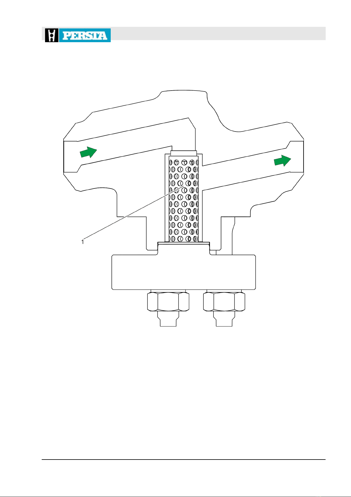
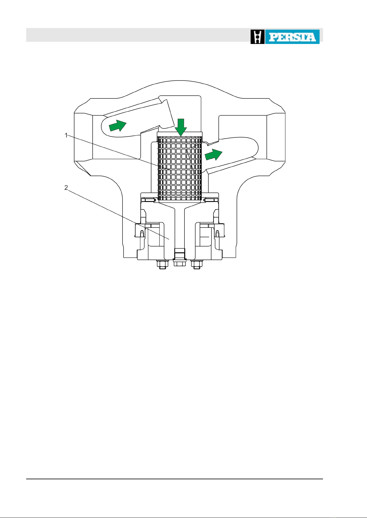
3.1 Mode of operation of the high pressure strainer......... 25
3.2 External seals............................................................. 26
3.2.1 High pressure strainer 990 ST................................. 26
3.2.2 High pressure strainer 990 SF................................. 27
3.3 Screen cylinder........................................................... 28
3.3.1 High pressure strainer 990 ST................................. 28
3.3.2 High pressure strainer 990 SF................................. 28
3.4 Connections................................................................ 29
4 Transport and storage...................................................... 31
4.1 Safety instructions for transport and storage.............. 31
4.2 Transport of packages................................................ 32
4.3 Storage of the valve.................................................... 32
4.4 Storage of spare parts................................................ 33
5 Installation......................................................................... 35
5.1 Safety notices for installation...................................... 35
5.2 Before the installation................................................. 36
5.3 Installing the valve...................................................... 36
5.4 After the installation.................................................... 37
5.4.1 Pickling the valve..................................................... 38
5.4.2 Painting the valve.................................................... 38
5.4.3 Executing the system pressure test and leak test... 38
5.4.4 Applying thermal insulation...................................... 39
6 Commissioning................................................................. 41
6.1 Safety notices for commissioning............................... 41
Table of contents
20.05.2021 High pressure strainer 990 ST/990 SF 5

6.2 Prior to commissioning............................................... 43
6.3 Executing the commissioning process........................ 43
7 Maintenance...................................................................... 45
7.1 Safety instructions for maintenance............................ 45
7.2 Maintenance schedule................................................ 49
7.3 Maintenance tasks...................................................... 49
7.3.1 Visually checking the valve...................................... 49
7.3.2 Cleaning the screen cylinder................................... 50
7.3.3 Replacing the gasket ring........................................ 52
7.3.4 Replacing the screen cylinder.................................. 59
7.3.5 Executing final tests on the sealed pressure sealing
bonnet...................................................................... 63
8 Faults and fault correction............................................... 65
8.1 Safety notices for fault correction............................... 65
8.2 Fault table................................................................... 67
9 Dismantling, disposal....................................................... 69
9.1 Safety notice for dismantling and disposal................. 69
9.2 Dismantling................................................................. 71
9.3 Disposal...................................................................... 72
10 Index................................................................................... 73
Table of contents
20.05.2021High pressure strainer 990 ST/990 SF6

1 Overview
Fig. 1: High pressure strainer 990 ST
High pressure strainer 990 ST
Overview
20.05.2021 High pressure strainer 990 ST/990 SF 7

Fig. 2: High pressure strainer 990 SF
The valve designated as high pressure strainer is designed for
installation in pipes.
By using the high pressure strainer, foreign objects in the pumping
medium are retained in the screen (Fig. 1/1, Fig. 2/1).
The fineness of filtration of the screen can be increased or reduced
depending on the mesh width of the screen.
Depending on its type, the high pressure strainer is supplied with a
pressure sealing bonnet (Fig. 2/2).
The following tools are required for the tasks described in the oper-
ating manual:
Forklift
Forklift with sufficient load-bearing capacity for transport of valves.
Hoist
Hoist with sufficient load-bearing capacity for transporting valves
and components.
Pin puncher
Mandrel-like tool for punching out the segment rings.
High pressure strainer 990 SF
Brief description - high pressure
strainer
Tools
Overview
20.05.2021High pressure strainer 990 ST/990 SF8

Sling gear
Functional and approved gear for attaching valves and compo-
nents on the hoist.
Overview
20.05.2021 High pressure strainer 990 ST/990 SF 9

Overview
20.05.2021High pressure strainer 990 ST/990 SF10

2 Safety
2.1 Symbols in this manual
Safety instructions are indicated by symbols in this manual. The
safety instructions are introduced by signal words that indicate the
scope of the hazard.
DANGER!
This combination of symbol and signal word indi-
cates a hazardous situation that, if not avoided, will
result in death or serious injury.
WARNING!
This combination of symbol and signal word indi-
cates a potentially hazardous situation that, if not
avoided, may result in death or serious injury.
CAUTION!
This combination of symbol and signal word indi-
cates a potentially hazardous situation that, if not
avoided, may result in minor or moderate injury.
NOTICE!
This combination of symbol and signal word indi-
cates a potentially hazardous situation that, if not
avoided, may result in damage to property.
ENVIRONMENT!
This combination of symbol and signal word indi-
cates potential hazards for the environment.
Safety instructions may refer to specific, individual instructions.
Such safety instructions are integrated into the specific instruction,
so that the flow of reading is not interrupted during performance of
the task. The signal words described above are used.
Safety instructions
Safety instructions in specific
instructions
Safety
Symbols in this manual
20.05.2021 High pressure strainer 990 ST/990 SF 11

Example:
1. Loosen the bolt.
2.
CAUTION!
Risk of getting trapped by the cover!
Close the cover carefully.
3. Tighten the bolt.
The following symbols are used in the safety instructions to indi-
cate special hazards:
Warning signs Type of danger
Warning – danger zone.
This symbol indicates useful tips and recommen-
dations as well as information on efficient and
trouble-free operation.
The following symbols are used throughout these instructions to
highlight specific instructions, results, lists, references and other
elements:
Symbol Explanation
Step-by-step instructions
ðResults of an action
References to sections of these operating
instructions and other applicable docu-
ments
Lists without a defined sequence
Special safety instructions
Tips and recommendations
Additional symbols
Safety
Symbols in this manual
20.05.2021High pressure strainer 990 ST/990 SF12

2.2 Intended use
Valves of the specified series are designed for installation in
pipes under the following conditions:
nUpright installation of the valve.
nOperation of the valve with liquid or gaseous media, without
particularly corrosive, chemical or abrasive influences.
nTemperature change speeds of maximum 6 K/min (6°C/min).
nMaximum number of 1000 load cycles between a depressur-
ised state and the maximum permissible pressure PS.
nAny number of load cycles at pressure fluctuations of up to
10 % of the maximum permissible pressure PS.
nGenerally used flow rates depending on the type of medium
and the application for which the valve is used.
nOperation of the valve without additional external influences,
such as pipe forces, vibrations, wind loads, earthquakes, cor-
rosive environments, fires, traffic loads, decomposition pres-
sures of unstable fluids.
nOperation of the valve only within the limits specified on the
rating plate (
Ä
“Rating plate” on page 14).
nIf the valve is operated in the creep range, the valve is
designed for a maximum operating time of 100,000 h. The
valve must be replaced afterwards.
nNo temperature increases were considered. In case of use in
the hot vapour area, temperature increases must be consid-
ered according to the regulations of the operating company.
nThe test pressure for a recurring test must not exceed the
maximum permitted pressure PS multiplied by 1.3.
nThe valve may only be operated if internal pressure loading is
predominantly dormant. Additional loads (e.g. stationary
thermal stress, unsteady pressure and temperature loads in
case of alternating loads or pipe loads) were not considered.
Intended use includes compliance with all the information con-
tained in this manual.
Any use that deviates from the intended use or any other form of
use constitutes misuse.
Safety
Intended use
20.05.2021 High pressure strainer 990 ST/990 SF 13

WARNING!
Danger in the event of misuse!
Misuse of the valve can cause dangerous situa-
tions.
– Connect the pipes so that they are free of ten-
sion.
– Pay attention to the correct installation position
of the valve.
– Do not exceed the number of permitted load
cycles (
Ä
Chapter 2.2 “Intended use”
on page 13).
– Do not use valves as an anchor point.
– Never operate valves at temperatures near or
below the freezing point of the pipeline medium.
2.3 Safety signs
The following symbols and instruction signs are in the work area.
These symbols and instruction signs refer to the immediate vicinity
in which they are affixed.
WARNING!
Danger if signs are illegible!
Over time, stickers and signs can become fouled
or can become illegible in some other manner, so
that dangers are not recognised and necessary
operating instructions cannot be complied with.
This results in a danger of injury.
– Keep all safety, warning, and operating instruc-
tions that are affixed to the device in legible con-
dition.
– Replace damaged signs or stickers immediately.
The rating plate is on the valve. Depending on the version, the fol-
lowing information is on the rating plate:
nConfirmation number
nArticle number
nYear of manufacture
nNominal diameter
nNominal pressure/design data
Misuse
Rating plate
Safety
Safety signs
20.05.2021High pressure strainer 990 ST/990 SF14

The flow direction is marked with an arrow on the valve (Fig. 3/1).
Additional markings (e.g. max. temperature limits) are available on
customer request.
2.4 Residual risks
The valve has been developed and manufactured to the state-of-
the-art and in accordance with generally accepted rules of safety.
Nevertheless residual risks remain that require careful handling.
The residual risks and the resulting behaviours and measures are
listed below.
2.4.1 Basic dangers at the workplace
DANGER!
Life-threatening danger due to failure to
comply with the rules of behaviour specified
for hazardous areas!
Depending on the version the valve can be used in
hazardous areas. There is life-threatening danger
if the rules of behaviour are not complied with
within these areas.
– Ensure that tasks on the valve can be executed
at the installation site.
Flow direction arrow
Fig. 3: Flow direction arrow
Customer-specific markings
Hazardous areas
Safety
Residual risks > Basic dangers at the workplace
20.05.2021 High pressure strainer 990 ST/990 SF 15

CAUTION!
Danger of injury due to tripping up!
There is a danger of fall injuries in the area of use
of the valve.
– Install cable and connection lines in such a
manner that there are no trip hazards.
2.4.2 Mechanical hazards
WARNING!
Risk of injury due to the heavy weight of the
valve!
The heavy weight of the valve, and of its compo-
nents, can result in severe injuries.
– Transport valves with a suitable hoist or forklift.
– If possible, lift valves via the bonnet.
– Use approved and functional sling gear.
– Safeguard valves and components from falling
over.
2.4.3 Thermal dangers
WARNING!
Danger of injury due to high/low temperatures!
Depending on the insert of the valve or of the pipe,
injuries can occur due to the high or low tempera-
ture of the components.
– When working on components or activating final
control equipment, wear protective equipment:
Protective gloves, protective goggles.
– Prior to performing tasks on these components,
allow them to cool down/warm up to ambient
temperature.
– Have the protective insulation provided by the
operating company attached.
Trip hazard
Heavy weight
Thermal dangers
Safety
Residual risks > Thermal dangers
20.05.2021High pressure strainer 990 ST/990 SF16

WARNING!
Danger of injury due to pipes shattering at
freezing temperatures!
As a result of pipes shattering at freezing tempera-
tures, severe injuries can be caused by fluid under
high pressure.
– Ensure that the valve is completely empty
before it is taken out of service.
– Never operate valves at temperatures close to,
or below the freezing point of the pumping
medium.
2.4.4 Hazards due to hazardous substances and operating materials
WARNING!
Pumping medium is a health hazard!
Contact with the pumping medium can have health
implications.
– Handle pumping medium in accordance with the
instructions in the manufacturer’s safety data
sheet.
– Wear protective equipment: Protective gloves,
safety footwear, protective goggles, protective
work clothing.
– Soak up escaped pumping medium without
delay and dispose of it in an environmentally
responsible manner.
WARNING!
Pickling medium is a health hazard!
Direct contact with the pickling medium used can
have health implications.
– Handle pickling medium in accordance with the
instructions in the manufacturer’s safety data
sheet.
– Wear protective equipment: Protective gloves,
safety footwear, protective goggles, protective
work clothing.
– Soak up escaped pickling medium without delay
and dispose of it in an environmentally respon-
sible manner.
Danger of freezing
Harmful pumping medium
Pickling medium
Safety
Residual risks > Hazards due to hazardous substances and operating materials
20.05.2021 High pressure strainer 990 ST/990 SF 17

WARNING!
Anticorrosive is a health hazard!
Direct contact with the anticorrosive used can have
health implications.
– Handle anticorrosive in accordance with the
instructions in the manufacturer’s safety data
sheet.
– Wear protective equipment: Protective gloves,
safety footwear, protective goggles, protective
work clothing.
– Soak up escaped anticorrosive without delay
and dispose of it in an environmentally respon-
sible manner.
NOTICE!
Damage of sealing surfaces and slide faces
due to the metallic processing of sealing sur-
faces and slide faces!
The metallic processing of sealing surfaces and
slide faces and valve parts can result in material
damage and malfunctions of the valve.
– Sealing surfaces and slide faces of gaskets
must not be
– scratched with a scraper,
– processed with wire brushes.
– Sealing surfaces and slide faces must be
– pulled off with emery cloth,
– processed with suitable abrasive tools or
– scraped off with plastic tools/wooden tools.
2.5 Behaviour in the event of an emergency
1. Shut off the pipe sections affected.
2. Comply with the plant regulations.
2.6 Responsibility of the operating company
The operating company is the company that operates the valve for
commercial or economic purposes itself or that provides it to a third
party for use, and that, during operation, bears the legal product
responsibility for protection of the user, personnel or third parties.
Anticorrosive
Damage of sealing surfaces and
slide faces
Operating company
Safety
Responsibility of the operating company
20.05.2021High pressure strainer 990 ST/990 SF18

The valve is used commercially. The operating company of the
valve is therefore subject to the legal occupational health and
safety obligations.
In addition to the safety instructions in this manual, the local occu-
pational health and safety, accident prevention and environmental
protection regulations that apply to the valve’s area of application
must be observed.
In this regard, the following applies in particular:
nThe operating company is responsible for the installation and
operation of the valve in the pipe.
nThe operating company must ensure that any dangerous situa-
tions caused by the operating conditions are avoided by instal-
ling additional safety systems.
nThe operating company must obtain information about the appli-
cable occupational health and safety regulations and, in a
hazard assessment, identify the additional hazards that may
exist at the installation site of the valve due to the specific
working conditions. The operating company must integrate this
information into operating instructions for the operation of the
valve.
nThe operating company must ensure that the operating instruc-
tions it has drawn up comply with the currently applicable legis-
lation throughout the operating period of the valve and, if neces-
sary, adapt the operating instructions.
nThe operating company must clearly define and assign the
responsibilities for installation, operation, fault correction, main-
tenance and cleaning.
nAfter the installation, the operating company must ensure the
proper pickling of the valve.
nThe operating company must provide equipment that ensures
the safe transition of the valve into a depressurised state.
nThe operating company must provide equipment that can com-
pletely drain the pipe sections in which the valve is installed as
well as the valve itself.
nThe operating company must ensure that all personnel who are
to handle the valve have read and understood this manual. In
addition, the operating company must train the personnel and
inform them of the hazards at regular intervals.
nThe operating company must provide the required protective
equipment for the personnel and instruct the personnel that
wearing the required protective equipment is compulsory.
nThe operating company must install additional protective
devices around the valve if contact with the valve can result in
injuries due to the medium in the pipe system.
The operating company is also responsible for keeping the valve in
proper working order at all times. Therefore, the following applies:
nThe operating company must ensure that the maintenance inter-
vals described in these instructions are complied with.
In the case of valves with different pipe connections on the inlet
and outlet ends, the operating company must ensure that when
opening the valve the respective pipe connection is not exposed to
impermissibly high pressure or an impermissibly high temperature.
Obligations of the operating com-
pany
Safety
Responsibility of the operating company
20.05.2021 High pressure strainer 990 ST/990 SF 19

2.7 Personnel requirements
WARNING!
Danger of injury due to inadequate personnel
qualification!
If unqualified personnel perform tasks on the
machine or are present in the danger zone, dan-
gers occur that can cause severe injury and signifi-
cant material damage.
– Only have activities performed by personnel
who are qualified to perform these activities.
– Keep unqualified personnel away from the
danger zones.
In this manual the qualifications of personnel for the various activity
areas are cited below:
Disposal contractor
A disposal contractor is a company qualified in accordance with
local regulations to collect, transport, store, handle, recycle or dis-
pose of waste and recyclables.
Forklift truck driver
The forklift truck driver has demonstrated to the operator their skills
in driving industrial trucks controlled by a sitting or standing oper-
ator and has been assigned to do this by the operator in writing.
Industrial mechanic (high pressure valves)
Based on their specialised training, skills, experience and knowl-
edge of the applicable standards and provisions, the industrial
mechanic is able to carry out the work assigned to them on instal-
lations and valves in the high pressure area and to independently
identify potential hazards and avoid them.
They have been instructed by the operator on how to handle the
plant and receive regular training.
The industrial mechanic is capable of maintaining and repairing
installations and valves in the high pressure area independently.
Pipeline engineer
Based on their specialised training, skills, experience and knowl-
edge of the applicable standards and provisions, the pipeline engi-
neer is able to carry out the work assigned to them and to inde-
pendently identify potential hazards and avoid them.
The pipeline engineer is able to install valves safely and properly in
the pipework.
Trained person (hoist)
The trained person (hoist) has been instructed, and can provide
evidence of this, by the operator on how to handle the hoist and
sling gear and the potential hazards associated with improper
behaviour.
Safety
Personnel requirements
20.05.2021High pressure strainer 990 ST/990 SF20
This manual suits for next models
1
Table of contents
Popular Industrial Equipment manuals by other brands

Isotech
Isotech HYDRA 798 User maintenance manual/handbook

Delta
Delta 46-461 instruction manual

Alfalaval
Alfalaval Toftejorg SaniJet 25 instruction manual

AirVac
AirVac DRS27 user manual

Cold Jet
Cold Jet Aero C100 Operator's manual

Johnson & Starley
Johnson & Starley AQUAIR 80 UNIVERSAL Installation, commissioning & servicing instructions

woodmizer
woodmizer LubeMizer manual

Lafferty
Lafferty VC-1016 Installation & operation instructions

COMPTROL
COMPTROL 36 instruction manual

Energy Absorption
Energy Absorption Safe-Stop 180 TMA 9181 Installation and operation manual

EGAmaster
EGAmaster ROSCAMATIC 100-4 operating instructions

ABB
ABB HT844020 Operation manual