Pertronic PS2 Quick start guide

PERTRONIC INDUSTRIES LTD
INSTALLATION NOTE
PS2 SOUNDER
Pertronic Industries Ltd 1 of 4 0301-PS2 Sounder Issue7 Oct 2002
Overview
The PS2 Sounder is one of a range of sounders manufactured by Pertronic Industries. The PS2
generates the evacuation and alert tones as specified by AS2220. The PS2 can also be used to
generate an alert signal acceptable to NZS4512:1997 (Amendment Two) by giving an
evacuation tone sweep every 15 seconds.
The PS2 has a maximum sound pressure level of 98dBA with a sound distribution pattern shown
below. The sound level may be adjusted by the volume control.
The PS2 is normally connected to the monitored bell or sounder circuit of a fire alarm panel and
to the LED drive output of a conventional or analogue addressable detector. The PS2 will sound
the evacuation tone when the detector is in alarm. If the bell circuit is reversed when the detector
is normal, the evacuation tone or alert tone will be sounded—depending on the state of the
ALERT IN terminal or jumper J3 of the PS2.
The PS2 may also be powered from the analogue addressable loop. In this case, the PS2 will
sound the evacuation tone when the detector is in alarm.
The PS2 may be mounted in a standard single-gang electrical flush-box fitting and is supplied
with a protective plastic cover for installation and building construction use.
Specification
Dimensions: 117mm (height)x 74mm (width), 12mm (depth above flush-box)
Designed to fit into a standard flush-box fitting.
Colour Options: Red or White.
Sound Level Output: Sound pressure level at 1m (3dB) Alert, Evacuation: 95dBA (12V)
98dBA (24V)
Power Requirements: BELL IN terminal (Supplied from the bell circuit or analogue loop):
Operating Voltage 9.5V to 30Vdc
Quiescent current (non alarm) 1.2A (12V, 24V)
Operating current (alarm state) 8mA average, 12mA peak (12V)
14mA average, 22mA peak (24V).
Controls: DETECTOR IN, DETECTOR OUT for detector activation (Evacuation).
Connect the detector LED output to the corresponding +/- terminals.
J4 for conventional or analogue addressable detectors:
Insert link for conventional detectors.
Remove link for analogue addressable detector.
ALERT IN, ALERT OUT for externally operated AS2220 tone control:
Open circuit for Evacuation on Bell reversal,
0V for Alert on Bell reversal.
J3 for internally operated AS2220 tone control:
Insert link for Alert on Bell reversal.
Remove link for Evacuation on Bell reversal.
Volume Control pcb-mounted potentiometer to adjust sound output
level. 20dB range.
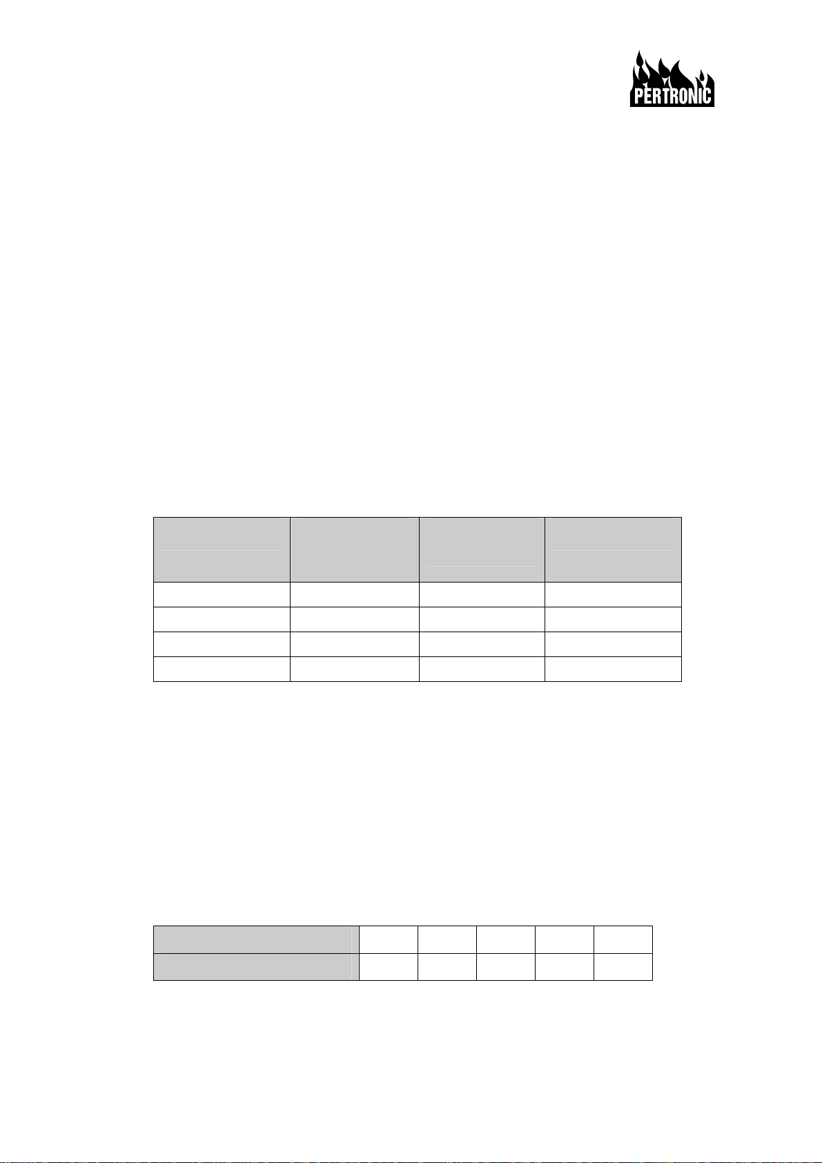
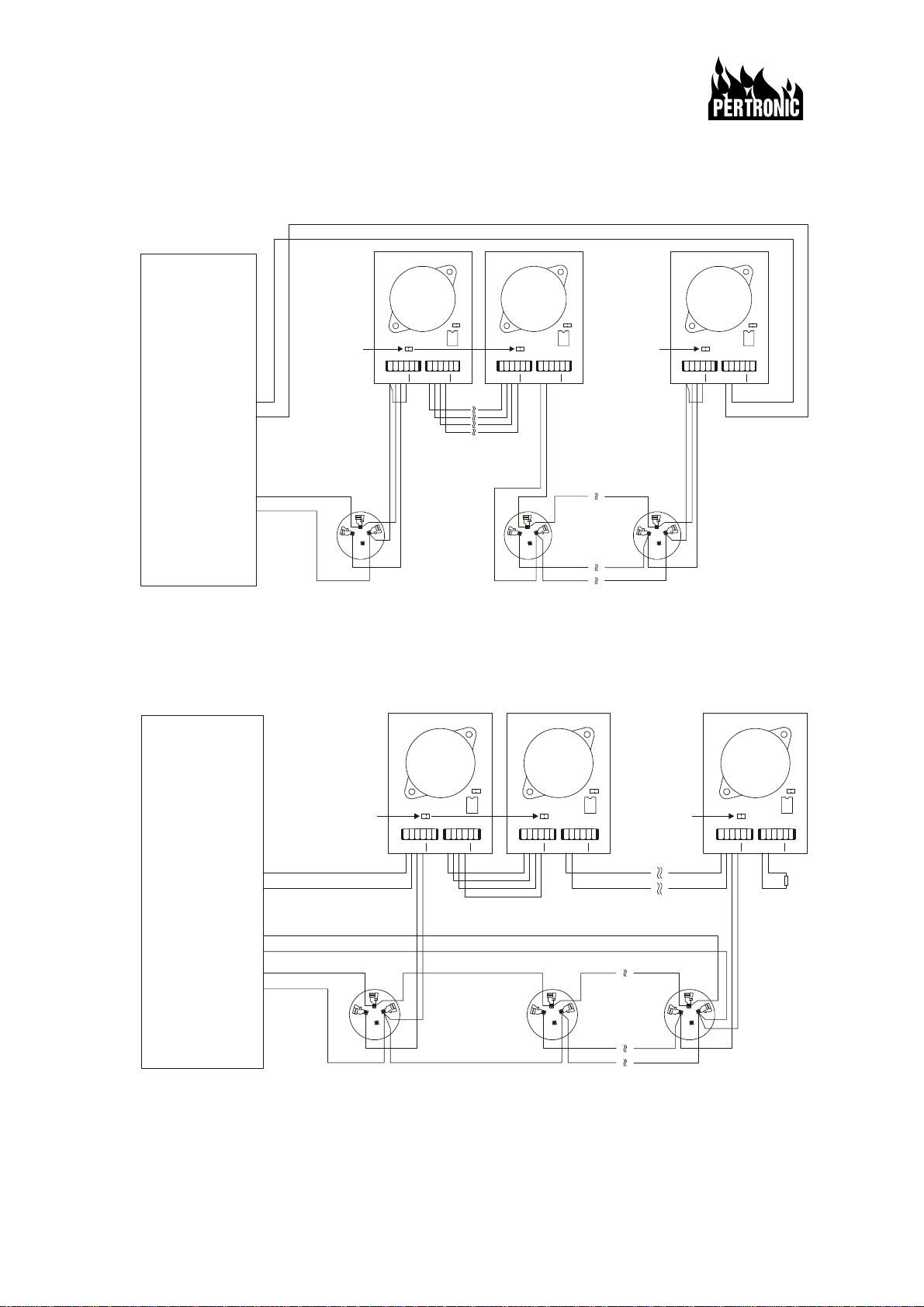
Multiple Operation: Up to 5 PS2 sounders may be controlled by the LED output of one
detector.
NOTE: J4 must be REMOVED for ANALOGUE detectors
J4 must be FITTED for CONVENTIONAL detectors

Pertronic Industries Ltd 2 of 4 0301-PS2 Sounder Issue7 Oct 2002
Operation
When the PS2 is connected only to the analogue addressable loop (no bells circuit—refer to
figure 1), only the evacuation tone is available. This is sounded when the connected detector or
detectors are in alarm.
When the panel bells or zonal bell driver are connected with the analogue addressable loop
connection (refer to figure 2), both evacuation and alert tones can be generated by the sounder.
This depends on the state of the ALERT IN terminal and on whether the connected detector or
detectors are in alarm. The table shows the effect of the inputs on the tone generated by the
PS2.
Figure 3 shows the configuration for conventional circuit operation. In this case the bells circuit
must be connected.
The ALERT IN (or ALERT OUT) terminal is connected directly or through a relay contact to the
battery negative or 0V to enable the alert tone when the bell circuit is reversed (no detector
alarm). (The ALERT IN and ALERT OUT terminals are physically connected together on the PS2
pcb). These terminals may be connected to other PS2 sounders in order to simultaneously
enable or disable the alert option.
The internal link, J3, may be used to permanently select the alert mode instead of externally
wiring via the terminals. Refer to figure 5 for the location of J3.
Up to 5 detectors may be connected in parallel to the Detector IN terminal to activate the PS2
from different detectors. Similarly, one detector can be wired to up to 5 PS2 sounders to activate
multiple sounders from one detector. These arrangements are shown in the figures.
PS2 Operation
Panel Bell Circuit Detector IN
(insert J4 for
conventional)
ALERT IN (or J3
inserted) Tone Generated
Monitor mode Normal Open None
Don’t care Active Don’t care Evacuate
Active Normal Open Evacuate
Active Normal 0V (inserted) Alert
Some bell driver circuits can provide a pulsed signal to the PS2 to give an alternative alert signal
using the evacuation tone. The sequence is: 3.75 seconds – evacuation tone (one cycle)
12 seconds – silence
3.75 seconds – evacuation tone
12 seconds – silence, (repeated).
This alternative alert signal complies with NZ4512.
Mixing Sounder Types
PS2 sounders may be connected to a group of PSB sounders so that the detector alarm can be
broadcast in near locations where there are no sounder bases.
Because of electrical loading, there are limitations to the number and type of sounder that may
be connected together. These limits are shown in the table:
Limits to the number of PS2s that may be connected to groups of PSBs
Up to 5 PS2s 4 PS2s 2 PS2s 2 PS2s 2 PS2s
May be connected to a group of 1 PSB 2 PSBs 3 PSBs 4 PSBs 5 PSBs
Note that the PS2s will not sound synchronously with the PSBs.

Pertronic Industries Ltd 3 of 4 0301-PS2 Sounder Issue7 Oct 2002
Connection Diagrams
Fig 1 F100 & F120 Loop Powered – Local Only
Fig 2 F100 & F120 – Local & Global Sounder Operation
Fire Alarm Panel
F100 & F120
Analogue
Loop In
J3
J4
Bell
IN
Det
IN
Alert
IN
Bell
OUT
Det
OUT
Alert
OUT
0V
+ - + - + - + -
0V
J3
J4
Bell
IN
Det
IN
Alert
IN
Bell
OUT
Det
OUT
Alert
OUT
0V
+ - + - + - + -
0V
+-
Multiple detectors may
operate up to 5 sounders
One detector may
operate up to 5 sounders
J4 removed
for analogue
detectors
J4 removed
for analogue
detectors
Analogue
Loop Out
3
2(+) 1(-)
3
2(+) 1(-) 3
2(+) 1(-)
+-
J3
J4
Bell
IN
Det
IN
Alert
IN
Bell
OUT
Det
OUT
Alert
OUT
0V
+ - + - + - + -
0V
System Sensor
B501 Detector
Base
or Pertronic PSB
Pertronic
PS2 Sounder
Analogue
Loop In
Analogue
Loop Out
+-
+-
Multiple detectors may
operate up to 5 sounders
One detector may
operate up to 5 sounders
3
2(+) 1(-)
3
2(+) 1(-) 3
2(+) 1(-)
+-
10k
EOL
Fire Alarm Panel
F100 & F120
J3
J4
Bell
IN
Det
IN
Alert
IN
Bell
OUT
Det
OUT
Alert
OUT
0V
+ - + - + - + -
0V
J3
J4
Bell
IN
Det
IN
Alert
IN
Bell
OUT
Det
OUT
Alert
OUT
0V
+ - + - + - + -
0V
J4 removed
for analogue
detectors
J4 removed
for analogue
detectors
J3
J4
Bell
IN
Det
IN
Alert
IN
Bell
OUT
Det
OUT
Alert
OUT
0V
+ - + - + - + -
0V
Pertronic
PS2 Sounder
System Sensor
B501 Detector
Base
or Pertronic PSB
Sounder Output
or other Sounder
Driver Board

Pertronic Industries Ltd 4 of 4 0301-PS2 Sounder Issue7 Oct 2002
Fig 3 Conventional Detector Operation
Fig 4 Connector Layout
Bell
IN
Det
IN
Alert
IN
Bell
OUT
Det
OUT
Alert
OUT
0V
+ - + - + - + -
0V
Fig 5 J3 / J4 Location
J4 must be REMOVED for
ANALOGUE detectors *
J4 must be FITTED for
CONVENTIONAL detectors
*J4 fitted with an analogue detector may
cause a bell fault.
Fig 6 AS2220 tone
characteristics
J3
J4
J3 inserted
for alert mode
0V
Fire Alarm Panel
10k
EOL
+-
To next
Detector
or EOL
123
4
Multiple detectors may
operate up to 5 sounders
One detector may
operate up to 5 sounders
To next
Detector
or EOL
123
4123
4
Circuit
M
+
Circuit
Close for Alert tone
on bell reversal
J4 fitted for
conventional
detectors
System
Sensor
B401
Detector Base
J4 fitted for
conventional
detectors
J3
J4
Bell
IN
Det
IN
Alert
IN
Bell
OUT
Det
OUT
Alert
OUT
0V
+ - + - + - + -
0V
J3
J4
Bell
IN
Det
IN
Alert
IN
Bell
OUT
Det
OUT
Alert
OUT
0V
+ - + - + - + -
0V
J3
J4
Bell
IN
Det
IN
Alert
IN
Bell
OUT
Det
OUT
Alert
OUT
0V
+ - + - + - + -
0V
Pertronic
PS2 Sounder
M
+
+
M
+
M
Sounder Output
or other Sounder
Driver Board
Other Pertronic Marine Equipment manuals
Popular Marine Equipment manuals by other brands

E2S
E2S D2xS2F Series instruction manual

System Sensor
System Sensor B200S-LF Installation and maintenance instructions

Simrad
Simrad PI32 datasheet

Scanstrut
Scanstrut Scanpod Deck Pod installation instructions

Veratron
Veratron LINK UP Series operating instructions

Yacht Sentinel
Yacht Sentinel YS PRO user manual