HESA MINISTILE Series User manual

Sirene elettroniche da interno
Serie MINISTILE
Manuale Installazione
DT02997_HE1223R00
2
Caratteristiche:
La sirena da interno MINISTILE è concepita per la segnalazione di allarme acustico (acustico
e visivo nella versione MINISTILE-BL). Dispone di due ingressi per attivare due suoni diversi,
di un trimmer e due DIP Switch che permettono la regolazione dell’intensità sonora per i sin-
goli ingressi. Ha inoltre un ingresso per comandare liberamente l’attenuazione del suono. Un
LED ad alta intensità è disponibile per segnalazioni ausiliarie indipendenti dall’allarme (solo
MINISTILE-BL).
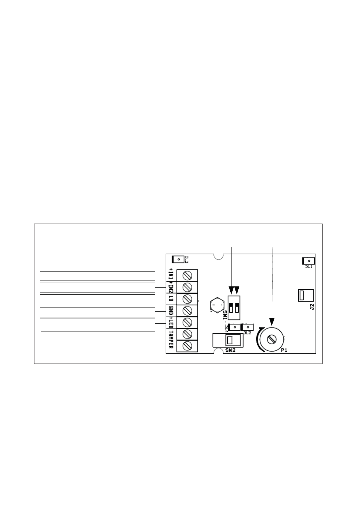
Collegamento:
Collegare l’uscita positiva della centrale, con almeno 55mA (80mA per MINISTILE-BL) ero-
gabili e limitata a 250mA, a uno dei morsetti positivi (+IN1 e/o +IN2), in base al morsetto col-
legato la sirena farà un tipo di suono e il negativo al morsetto GND come in Fig. 1.
Per regolare l’intensità sonora, da 80dB a 103dB, ruotare il trimmer P1 in senso orario.
Se si vuole comandare dalla centrale anche l’attenuazione, ad es. per segnalare un preal-
larme, collegare un’uscita ausiliaria della centrale al morsetto LO, quando il morsetto è por-
tato ad una tensione positiva l’intensità sonora diminuisce di circa 10dB. Per settare gli
ingressi IN1 e IN2 attenuati di circa 10 dB senza comando LO impostare i dip switch1 (per
+IN2) e/o 2 (per +IN1) in ON.
Quando al morsetto +LED viene fornita una tensione positiva il led DL2 a bordo della sirena
si accende fisso (solo MINISTILE-BL).
Montaggio:
La sirena deve essere installata da personale qualificato all’interno degli edifici tenendo in
considerazione tutte le norme riguardanti l’installazione rispettando distanze e altezze per
la miglior resa visiva e acustica della stessa.
Fissare la MINISTILE a muro attraverso le 4 asole nel fondo della sirena utilizzando 4
tasselli da 5 mm.
Per il collegamento dei cavi utilizzare un giunto (tubo scatola) nel caso di un impianto con
tubi o canaline esterni.
In
g
resso sirena: +13,8 Vc.c.
Ingresso bitonale: +13,8 Vc.c.
Ingresso attenuazione: +13,8 Vc.c.
Alimentazione: Ne
g
ativo
Comando LED DL2: +13,8 Vc.c.
Colle
g
are alla linea Tamper
a
centrale
Trimmer di
Re
g
olazione Volume
DIP di attenuazione
Suono 2 e 1
* Solo MINISTILE-BL Figura 1
*

3
Frequenze:
Morsettiera:
Caratteristiche tecniche:
Morsetto Suono Frequenza
min. max
+IN1 Sirena standard, andamento trapezoidale 2550Hz - 2850Hz
+IN2 Pulsante bitonale 2350Hz - 2960Hz
Morsetto Funzione Parametri
+IN1 Ingresso comando suono
sirena standard
MINISTILE:
I assorbita con volume medio 55mA
I assorbita con volume al massimo 105mA
MINISTILE-BL:
I assorbita con volume medio 80mA
I assorbita con volume al massimo 130mA
+IN2 Ingresso comando suono
bitonale
MINISTILE:
I assorbita con volume medio 55mA
I assorbita con volume al massimo 105mA
MINISTILE-BL:
I assorbita con volume medio 80mA
I assorbita con volume al massimo 130mA
LO Ingresso comando d
attenuazione suono I MAX assorbita 2mA
GND Alimentazione negativa –
+LED (solo MINISTILE-BL)
Comando LED DL2 I MAX assorbita 10mA
TAMPER Ingresso a contatti puliti
normalmente chiuso –
Tensione nominale di alimentazione (Vn) 13,8 Vc.c (da 10 Vc.c. a 14 Vc.c.)
Assorbimento massimo con Vn vedi tabella sopra
Potenza 2,4 W
Potenza sonora SPL @ 1m 98 dB
Frequenza suono Vedi tabella
Grado Sicurezza Grado 3
Conforme alla Norme EN50131-4
Grado di Protezione IP4X
Classe ambientale II
Temperatura di funzionamento da -25 °C a +50°C
Dimensione 159x114x52 mm
DT02997_HE1223R00
MANUTENZIONE PERIODICA
Si raccomanda di provare la sirena ogni settimana, e di fare effettuare
la manutenzione periodica da un installatore professionista
Questa apparecchiatura deve essere installata da un tecnico
professionalmente qualificato per le installazioni di impianti di sicurezza.
Dichiarazione di conformità:
Hesa S.p.A., Via Triboniano, 25 - 20156 MILANO dichiara che le sirene autoalimentate Serie MINISTILE sono
conformi ai requisiti essenziali richiesti dalla normativa comunitaria:
CE 2014/30; CE 214/35; UE 2011/65
Sono stati applicati i seguenti documenti normativi:
EN 60950-1+A12:2011+A2:2013
EN 50130-4:2012+A1:2014
EN 61000-6-3:2011+AC1:2012
EN 50581:2012
5
PRODUCT DESCRIPTION:
-).)34),% ", indoor sounder is a device conceived for both acoustic and visual notice in alarm installations.
Technical features: two inputs to activate two different sounds, trimmer, two dipswitches enabling sound pressure
adjustment for the various inputs, input for sound softening control, high-intensity independent LED flashing
unit for optical signalizations.
TECHNICAL FEATURES:
Power supply
13.8 Vdc (from 10 Vdc to 14 Vdc)
Max consumption with Vn
See CHART 2
Power
2.4 W
Sound pressure SPL @ 1m
See DIAGRAM 1
Sound frequency
See CHART 1
Working condition
From -25°C to +50°C
Environmental class
Class II
IP degree
IP4x
Standards compliance
EN50131-4:2009
T031:2014
Security
3
Size (HxWxD)
159x113x53
Weight
180 gr
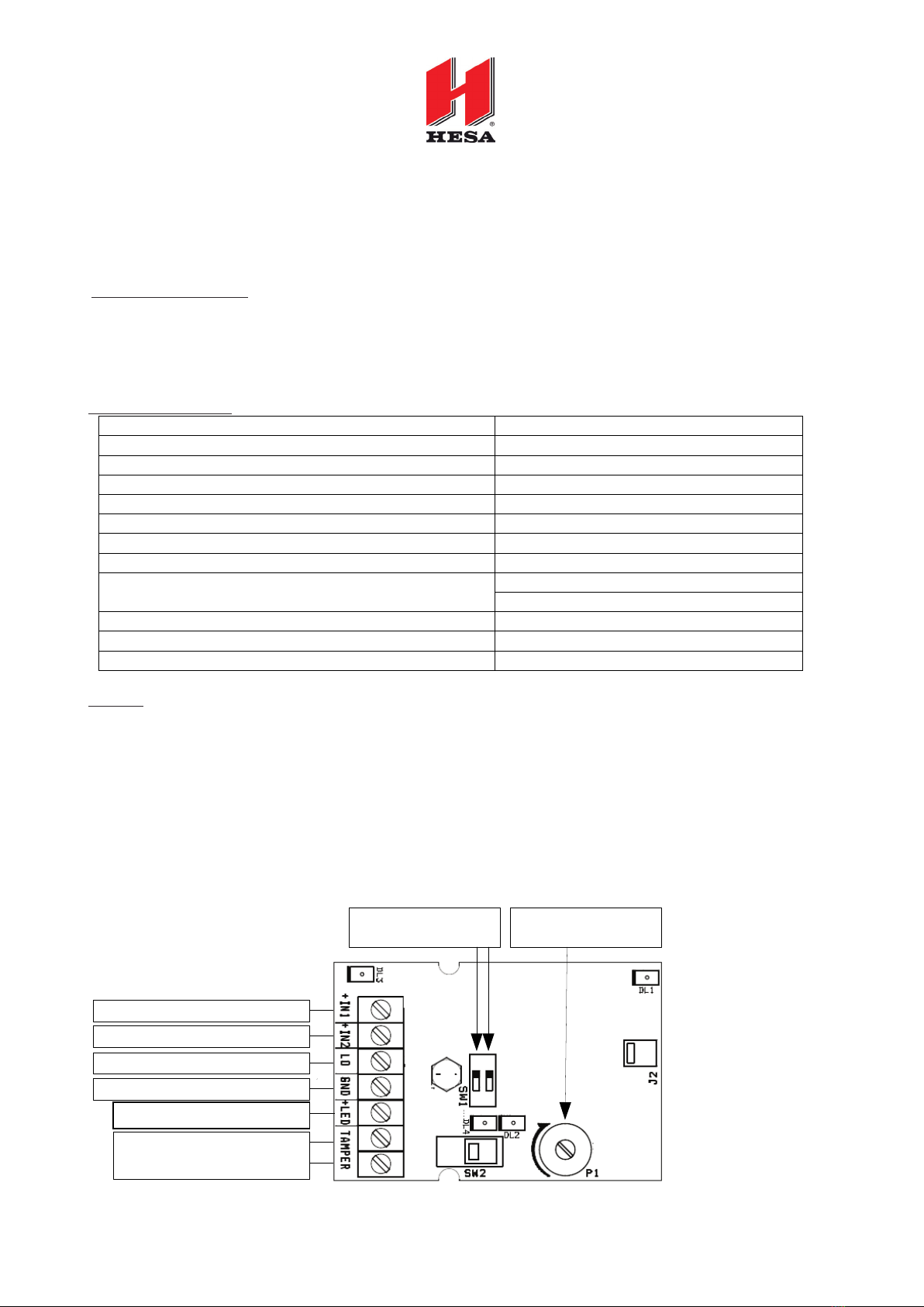
WIRING:
As shown in Pict. 1, connect the negative to GND terminal and the positive output of the control panel (delivering min.
80mA and limited to 250mA) to one of the positive terminals (+IN1 and/or +IN2). According to the terminal connected,
the sounder produces a sound type.
To adjust the sound pressure (from 80 dB to MAX), rotate P1 trimmer clockwise.
To control the sound softening directly from the control panel (e.g. to notify a pre-alarm), connect an auxiliary output
of the control panel to LO terminal: when the terminal is brought to a positive voltage, the sound pressure decreases
of around 10 dB. For IN1 and IN2 inputs already to be softened of around 10 dB (without LO command), set dipswitch
1 (in case of +IN2) and/or dipswitch 2 (in case of +IN1) in ON position.
When the terminal +LED is brought to a positive voltage, the led DL2 on the sounder flashes steadily.
SOUNDER INPUT: +13.8 Vdc
BI-TONE INPUT: +13.8 Vdc
INPUT FOR SOUND SOFTENING: +13.8 Vdc
POWER SUPPLY: NEGATIVE
CONNECT TO THE TAMPER
LINE OF THE CONTROL PANEL
TRIMMER FOR VOLUME
ADJUSTMENT
DIPSWITCHES 2 AND 1
FOR SOUND SOFTENING
LED DL2 INPUT: +13.8 Vdc
Pict.1
-).)34),%",(%",
INDOOR SOUNDER
INSTALLATION MANUAL

6
Diagram 1
MOUNTING:
Attention: the sounder must be installed by qualified staff, in indoor location, keeping into consideration all related
norms and measures and respecting proper distances and installation heights to the purpose of obtaining the best
acoustic and optical notice results from the device.
1. Remove the cover and fix the sounder on the wall through the 4 fixing holes located on the sounder base (see Pict.
2) and using 4 5-mm wall plugs;
2. For the wiring: use a joint in case of installation with external pipes.
3. Once connection has been performed, close the sounder by screwing the closing screw through the hole located
in the front part of the sounder, as shown in Pict. 3.
Tab. 1
CHART 1: SOUND PRESSURE AND FREQUENCIES
TERMINAL
SOUND
FREQUENCY
min. max.
+IN1
Standard sounder, trapezoidal type
2550Hz - 2850Hz
+IN2
Bi-tone pulsed
2350Hz - 2960Hz
-).)34),%",
Angle
dB (A) @1m
15°
92.0
45°
90.7
75°
97.1
105°
96.8
135°
90.3
165°
92.2
Pict.3
Hole for fixing screw
Fixing holes for
anti-removal tamper
Fixing holes
Pict.2
97.1
7
Page 3 of 4
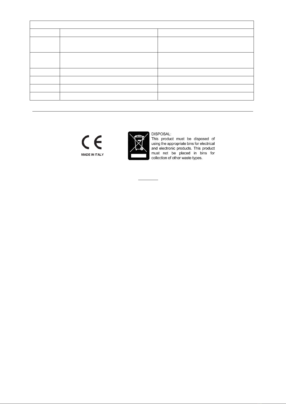
CHART 2: TERMINAL BLOCK
TERMINAL
FUNCTION
PARAMETRES
+IN1
Input for standard sound
consumed with medium volume 80mA
consumed with max volume 130mA
+IN2
Input for bi-tone sound
consumed with medium volume 80mA
consumed with max volume 130mA
LO
Input for sound softening control
MAX consumed 2mA
GND
Negative power supply
-
+LED
DL2 LED input
MAX consumed 10mA
TAMPER
Dry-contact NC input
-
Attention: give power supply to the sounder using a control panel output with SELV voltage and limited power!
Warranty:
All Venitem products have 2 years warranty. With the aim of improving design and quality of its products, Venitem
reserves the right to modify them without prior notice. All defective products have to be returned to the supplier.

8
DT02997_HE1223R00
This manual suits for next models
1
Table of contents
Languages:


