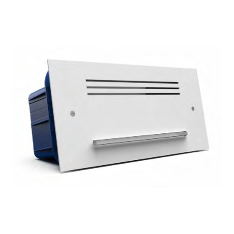
Venitem MINI DOGE User manual

IT
EN
MINI DOGE
MANUALE TECNICO
TECHNICAL MANUAL

2
AVVERTENZA
Pressione sonora elevata, rischi di
danni all’udito.
Rischio di esplosione se la batteria è
sostituita con un tipo errato.
ISTRUZIONI DI SICUREZZA IMPORTANTI
Leggere attentamente questa sezione e conservarla
WARNING
High sound pressure, risk of
hearing loss.
Explosion risk if the battery is
replaced with a wrong type.
IMPORTANT SAFETY INSTRUCTIONS
Read the following section carefully and store it

MANUALE TECNICO
3
DESCRIZIONE
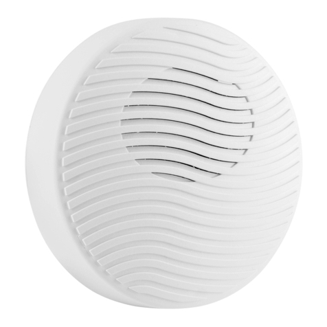
MOD. MINI DOGE: Avvisatore acustico di allarme, evacuazione e controllo per uso in ambienti
riparati dalle intemperie.
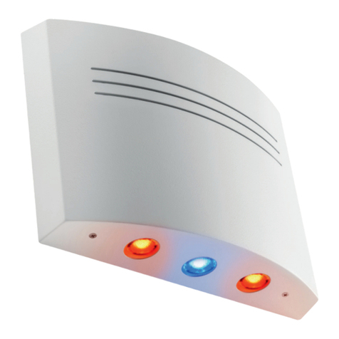
MOD. MINI DOGE L: Come Mini Doge con in più LED BLU di stato impianto e LED Flash di
allarme.
MOD. MINI DOGE A: Avvisatore acustico di allarme autoalimentato, evacuazione e controllo
per uso in ambienti riparati dalle intemperie.
MOD. MINI DOGE AL: Come Mini Doge A con in più LED BLU di stato impianto e LED Flash di
allarme.
LED ANOMALIE
(Versione A-AL)
VOLUME
DIP SWITCH
M1
1
M2
2
M3
3
M4
4
M5
5
M6
6+
M7
7–
M8 M9 M10
OUT
ANM
T
A
M
P
E
R
RT1
DL1
DL3
SW2
DL2
LD1
SW1
J1
+
–
P1
Inserire qui il cacciavite
per aprire la sirena
Fig. 2
Fig. 1
Asole per il fissaggio
Asola per tamper a
strappo dalla parete
Foro viti di chiusura
MONTAGGIO:
La sirena deve essere installata da personale qualificato all’interno degli edifici tenendo in
considerazione tutte le norme riguardanti l’installazione rispettando distanze e altezze per la
miglior resa visiva e acustica della stessa.
Per aprire la sirena svitare la vite, inserire un cacciavite nel foro segnalato dalla freccia nella
fig.2 e sollevare il coperchio. Fissare la sirena a muro attraverso le 4 asole nel fondo della sire-
na utilizzando 4 tasselli da 5 mm (ved. Fig.1).
Per il collegamento dei cavi utilizzare un giunto (tubo scatola) nel caso di un impianto con tubi
o canaline esterni.

4
MINI DOGE / MINI DOGE L
COLLEGAMENTO MORSETTI
MORSETTO COLLEGAMENTO
1Comando (positivo = Attivo) del LED di segnalazione impianto allarme
acceso / spento (Versione L)
2Comando (positivo = Attivo) indipendente del lampeggiante di allarme
(vedi DIP 1) (Versione L)
3Comando (positivo = Attivo) suono 1 (DIP 4 = OFF) - suono 4 (DIP 4 = ON)
3 & 4 Comando (positivo = Attivo) suono 7 (DIP 4 = OFF) - suono 4 (DIP 4 = ON)
4Comando (positivo = Attivo) suono 2 (DIP 4 = OFF) - suono 5 (DIP 4 = ON)
4 & 5 Comando (positivo = Attivo) suono 8 (DIP 4 = OFF) - suono 5 (DIP 4 = ON)
5Comando (positivo = Attivo) suono 3 (DIP 4 = OFF) - suono 6 (DIP 4 = ON)
6Morsetto libero
70 Vcc – Massa
8Tamper (connettere alla linea tamper della centrale)
9Tamper (connettere alla linea tamper della centrale)
NB: Alimentare la sirena utilizzando un’uscita della centrale con tensione SELV e potenza
limitata.
SETTAGGIO DIP-SWITCH
DIP 1 – SELEZIONE LAMPEGGIANTE (Versione L)
OFF Il lampeggiante segue il comando di allarme (da fabbrica)
ON Il lampeggiante segue l’ingresso di comando lampeggiante separato - Morsetto 2
DIP 2 – OFF (NON MODIFICARE)
DIP 3 – OFF (NON MODIFICARE)
DIP 4 – SELEZIONE SUONI
OFF
Suono 1 Allarme modulato morsetto 3
Suono 2 Allarme Venitem modulato morsetto 4
Suono 3 Preallarme attenuato intermittente morsetto 5
Sound 7 Allarme modulato morsetti 3 + 4
Sound 8 Allarme impulsi rapidi morsetti 4 + 5
(da fabbrica)
ON
Suono 4 Evacuazione Bitonale di allarme Immediato morsetto 3 o 3 + 4
Suono 5 Evacuazione Continuo di allarme frequenza fissa morsetto 4 o 4 + 5
Suono 6 Evacuazione Intermittente di preallarme morsetto 5

MANUALE TECNICO
5
Tensione nominale 13,8 Vcc
Tensione minima 10 Vcc
Tensione massima 16 Vcc
Assorbimento max in allarme 170 mA (350 mA picco) +/-10 mA
Assorbimento max in preallarme 80 mA (100 mA picco) +/-10 mA
Assorbimento e potenza suono regolabili Assorbimento da 20 mA a 170 mA
Assorbimento massimo lampeggianti
morsetti 1, 2 (Versione L) 12 mA
CARATTERISTICHE TECNICHE
TABELLA SUONI
SUONO MODULAZIONE LIMITI DI MODULAZIONE (Hz)
Suono 1 Trapezoidale (CERTIFICATO) 1.200 – 2.300
Suono 2 Sale - scende 1.800 – 3.900
Suono 3 Impulsata (attenuata) 1.600
Suono 4 Due toni 1.800 – 3.800
Suono 5 Continuo 1.600
Suono 6 Impulsata 1.800
Suono 7 Sale - Stabile - Scende - Stabile 1.400- 1.600
Suono 8 Impulsata veloce 1.800
96,3 dB
DIAGRAMMA 1
MINI DOGE - MINI DOGE L
SUONO 1
Angolo dB (A) @ 1 m
15° 93,7
45° 92,2
75° 96,0
105° 96,3
135° 92,3
165° 94,2
DIP 5 – SELEZIONE TEMPORIZZAZIONE SUONO
OFF Durata allarme segue il comando (da fabbrica)
ON Durata suono di allarme 8 minuti mentre il lampeggiante (solo versione L) segue il
comando
REGOLAZIONE VOLUME E CORRENTE ASSORBITA
Ruotare il trimmer P1 per impostare la potenza e la corrente assorbita.
6
COLLEGAMENTO MORSETTI
MORSETTO COLLEGAMENTO
1Comando (negativo = Attivo) del LED di segnalazione impianto allarme
acceso / spento (Versione AL)
2Comando (positivo = Attivo) indipendente del lampeggiante di allarme
(vedi DIP 1) (Versione AL)
3Comando suono 1 (DIP 4 = OFF) - suono 4 (DIP 4 = ON)
Vedi impostazione DIP2 e DIP3 per tipo di comando
3 & 4 Comando suono 7 (DIP 4 = OFF) - suono 4 (DIP 4 = ON)
Vedi impostazione DIP2 e DIP3 per tipo di comando
4Comando suono 2 (DIP 4 = OFF) - suono 5 (DIP 4 = ON)
Vedi impostazione DIP2 e DIP3 per tipo di comando
4 & 5 Comando suono 8 (DIP 4 = OFF) - suono 5 (DIP 4 = ON)
Vedi impostazione DIP2 e DIP3 per tipo di comando
5Comando suono 3 (DIP 4 = OFF) - suono 6 (DIP 4 = ON)
Vedi impostazione DIP2 e DIP3 per tipo di comando
6+12 Vcc - Alimentazione e ricarica
70 Vcc – Massa
8Tamper (connettere alla linea di allarme tamper della centrale)
9Tamper (connettere alla linea di allarme tamper della centrale)
10 Uscita anomalia. Nessuna anomalia = 0 Vcc; anomalia = libero
N.B. Nel caso di collegamento con comando a mancare collegare al positivo o negativo
(vedi DIP2) tutti i morsetti di comando.
MINI DOGE A / MINI DOGE AL
Livello massimo SPL @ 1 m Vedi diagramma 1
8 suoni 3 Modulati, 3 impulsati, 1 bitonale, 1
continuo
Temporizzazione Allarme Infinito o 8 minuti
Doppio tamper con micro-switch Antiapertura e antistrappo
Condizioni ambientali -25 °C / +50 °C
Classe ambientale II
Grado di sicurezza 3
Grado di protezione IP4x
Conforme
alla Norma
Ente certificatore
(IMQ-SISTEMI DI SICUREZZA)
T031:2017 + A1:2018
EN50131-4:2019
Dimensioni (HxLxP) 155x100x53 mm
Peso 240 gr

MANUALE TECNICO
7
TABELLA SUONI
SUONO MODULAZIONE LIMITI DI MODULAZIONE (Hz)
Suono 1 Trapezoidale (CERTIFICATO) 1.200 – 2.300
Suono 2 Sale - scende 1.800 – 3.900
Suono 3 Impulsata (attenuata) 1.600
Suono 4 Due toni 1.800 – 3.800
Suono 5 Continuo 1.600
Suono 6 Impulsata 1.800
Suono 7 Sale - Stabile - Scende - Stabile 1.400- 1.600
Suono 8 Impulsata veloce 1.800
SETTAGGIO DIP-SWITCH
DIP 1 – SELEZIONE LAMPEGGIANTE (Versione AL)
OFF Il lampeggiante segue il comando di allarme (da fabbrica)
ON Il lampeggiante segue l’ingresso di comando lampeggiante separato - Morsetto 2
DIP 2 – SELEZIONE COMANDO POSITIVO / NEGATIVO
OFF Comando positivo - Morsetti 3, 4, 5 (da fabbrica)
ON Comando negativo - Morsetti 3, 4, 5
DIP 3 – SELEZIONE COMANDO A MANCARE / A DARE
OFF Comando a dare - Morsetti 3, 4, 5
ON Comando a mancare - Morsetti 3, 4, 5 (da fabbrica)
DIP 4 – SELEZIONE SUONI
OFF
Suono 1 Allarme modulato morsetto 3
Suono 2 Allarme Venitem modulato morsetto 4
Suono 3 Preallarme attenuato intermittente morsetto 5
Sound 7 Allarme modulato morsetti 3 + 4
Sound 8 Allarme impulsi rapidi morsetti 4 + 5
(da fabbrica)
ON
Suono 4 Evacuazione Bitonale di allarme Immediato morsetto 3 o 3 + 4
Suono 5 Evacuazione Continuo di allarme frequenza fissa morsetto 4 o 4 + 5
Suono 6 Evacuazione Intermittente di preallarme morsetto 5
DIP 5 – SELEZIONE TEMPORIZZAZIONE SUONO
OFF Durata allarme segue il comando (da fabbrica)
ON Durata suono di allarme 8 minuti mentre il lampeggiante (solo versione AL) segue il
comando
REGOLAZIONE VOLUME E CORRENTE ASSORBITA
Ruotare il trimmer P1 per impostare la potenza e la corrente assorbita.
8
TABELLA ANOMALIE
ANOMALIA LED ROSSO
LD1 USCITA OUT ANM
Mancanza corrente di ricarica (Vcc ricarica < 10 Vcc)
(test ogni 10s) 2 LAMPEGGI APERTO
Batteria sconnessa (test ogni 12 ore) 3 LAMPEGGI APERTO
Batteria scarica (V batteria < 6,5 Vcc) (test ogni 10 s) 4 LAMPEGGI APERTO
Batteria deteriorata (< 6,5 Vcc) – non mantiene la
carica (test ogni 12 ore) 5 LAMPEGGI APERTO
Nessuna anomalia OFF 0 Vcc
Per resettare l’anomalia rimuovere la causa dell’anomalia, attendere 10 secondi e dare un
comando su un morsetto di ingresso (2, 3, 4, 5).
Per far ripartire il test anomalie, levare completamente l’alimentazione alla sirena scollegando
il pacco batterie e il morsetto di ricarica.
NB: Alimentare la sirena utilizzando un’uscita della centrale con tensione SELV e potenza
limitata.
100,6 dB
DIAGRAMMA 2
MINI DOGE A/AL
SUONO 1
Angolo dB (A) @ 1 m
15° 97,4
45° 96,8
75° 100,6
105° 100,4
135° 97,6
165° 99,1

MANUALE TECNICO
9
Tensione nominale 13,8 Vcc
Tensione minima 10 Vcc
Tensione massima 16 Vcc
Assorbimento ricarica batteria 40 mA
Assorbimento max in allarme 170 mA (350 mA picco) +/-10 mA
Assorbimento max in preallarme 80 mA (100 mA picco) +/-10 mA
Assorbimento e potenza suono regolabili Assorbimento da 20 mA a 170 mA
Assorbimento massimo lampeggianti
morsetti 1, 2 (Versione AL) 12 mA
Livello massimo SPL @ 1 m Vedi diagramma 2
8 suoni 3 Modulati, 3 impulsati, 1 bitonale, 1
continuo
Temporizzazione Allarme Infinito o 8 minuti
Doppio tamper con micro-switch Antiapertura e antistrappo
Condizioni ambientali -25 °C / +50 °C
Classe ambientale II
Grado di sicurezza 3
Grado di protezione IP4x
Batteria (Ni-Mh) 8,4 Vcc 700 mA o 8,4 Vcc 800 mA
Conforme
alla Norma
Ente certificatore
(IMQ-SISTEMI DI SICUREZZA)
T031:2017 + A1:2018
EN50131-4:2019
Dimensioni (HxLxP) 155x100x53 mm
Peso 328 gr
Certificato per il Belgio
Conforme alla norma T031
MADE IN ITALY
GARANZIA
Tutti i prodotti Venitem sono garantiti contro i difetti di fabbricazione o di materiale. Nell’intento
di migliorare il design e la qualità dei propri prodotti la ditta Venitem si riserva di modificare il
prodotto senza alcun preavviso. Tutti i prodotti guasti o difettosi vanno resi al proprio fornitore.
CARATTERISTICHE TECNICHE

10
AVVERTENZA
Pressione sonora elevata, rischi di
danni all’udito.
Rischio di esplosione se la batteria è
sostituita con un tipo errato.
ISTRUZIONI DI SICUREZZA IMPORTANTI
Leggere attentamente questa sezione e conservarla
WARNING
High sound pressure, risk of
hearing loss.
Explosion risk if the battery is
replaced with a wrong type.
IMPORTANT SAFETY INSTRUCTIONS
Read the following section carefully and store it

TECHNICAL MANUAL
11
DESCRIPTION
MOD. MINI DOGE: device conceived for acoustic notice in alarm, evacuation and monitoring
systems – usage in covered locations properly protected against bad weather conditions.
MOD. MINI DOGE L: features as per Mini Doge, with BLUE LED flashing unit (serving both as
optical notice and as system status ON/OFF notice).
MOD. MINI DOGE A: self-supplied device conceived for acoustic notice in alarm, evacuation
and monitoring systems – usage in covered locations properly protected against bad weather
conditions.
MOD. MINI DOGE AL: features as per Mini Doge A, with BLUE LED flashing unit (serving both
as optical notice and as system status ON/OFF notice).
ANOMALY LED
(A-AL MODELS)
VOLUME
DIP-SWITCHES
M1
1
M2
2
M3
3
M4
4
M5
5
M6
6+
M7
7–
M8 M9 M10
OUT
ANM
T
A
M
P
E
R
RT1
DL1
DL3
SW2
DL2
LD1
SW1
J1
+
–
P1
Insert the screwdriver here
to open the sounder
Pict. 2
Pict. 1
Fixing holes
Hole for anti-removal
tamper
Screw hole
MOUNTING:
The sounder must be installed by qualified staff, in indoor locations, keeping into consideration
all related norms and measures and respecting proper distances and installation heights to
the purpose of obtaining the best acoustic and optical notice results from the device.
To open the sounder, unscrew the closing screw, insert a screwdriver in the hole as shown by
the arrow in Pict. 2 and take off the cover. Fix the siren on the wall through the 4 fixing holes
located on the sounder base (see Pict. 1) using 4 5-mm wall plugs.
For the wiring: use a joint in case of installation with external pipes.

12
MINI DOGE / MINI DOGE L
TERMINAL CONNECTIONS
TERMINAL CONNECTION
1Trigger (positive = activated) of the LED devoted to the notice of the alarm system status
(alarm system armed/disarmed) - on L Model only
2Independent trigger of the LED flashing unit for alarm optical notice (positive = activated)
- see DIP 1, L Model only
3Sound 1 (positive = activated) command (DIP 4 = OFF) - sound 4 command (DIP 4 = ON)
3 & 4 Sound 7 (positive = activated) command (DIP 4 = OFF) - sound 4 command (DIP 4 = ON)
4Sound 2 (positive = activated) command (DIP 4 = OFF) - sound 5 command (DIP 4 = ON)
4 & 5 Sound 8 (positive = activated) command (DIP 4 = OFF) - sound 5 command (DIP 4 = ON)
5Sound 3 (positive = activated) command (DIP 4 = OFF) - sound 6 command (DIP 4 = ON)
6Free terminal
70 Vdc – Ground
8Tamper (connect to the tamper line coming from the control panel)
9Tamper (connect to the tamper line coming from the control panel)
ATTENTION: give power supply to the sounder using a control panel output with SELV
voltage and limited power.
DIP-SWITCHES SETTING
DIP 1 – FLASHING UNIT SELECTION (L model)
OFF The flashing unit follows the alarm trigger (default setting)
ON The flashing unit follows the separated flashing unit trigger - terminal no. 2
DIP 2 – OFF (DO NOT MODIFY)
DIP 3 – OFF (DO NOT MODIFY)
DIP 4 – SOUND SELECTION
OFF
Sound 1 Modulated alarm – terminal no. 3
Sound 2 Venitem modulated alarm – terminal no. 4
Sound 3 Pre-alarm softened intermittent – terminal no. 5
Sound 7 Modulated alarm – terminals no. 3 and 4
Sound 8 Pulsed fast alarm – terminals no. 4 and 5
(default setting)
ON
Sound 4 Bi-tone immediate evacuation alarm – terminal no. 3 or 3 + 4
Sound 5 Fixed frequency continuous evacuation alarm– terminal no. 4 or 4 + 5
Sound 6 Pulsed intermittent pre-alarm sound for evacuation – terminal no. 5

TECHNICAL MANUAL
13
SOUND CHART
SOUND MODULATION MODULATION LIMITS (Hz)
Sound 1 Trapezoidal (CERTIFIED) 1,200 – 2,300
Sound 2 Increasing – decreasing 1,800 – 3,900
Sound 3 Pulsed (softened) 1,600
Sound 4 Two tones 1,800 – 3,800
Sound 5 Continuous 1,600
Sound 6 Pulsed 1,800
Sound 7 Increasing-Stable-Decreasing-Stable 1,400 – 1,600
Sound 8 Pulsed fast 1,800
96.3 dB
DIAGRAM 1
MINI DOGE - MINI DOGE L
SOUND 1
Angle dB (A) @ 1 m
15° 93.7
45° 92.2
75° 96.0
105° 96.3
135° 92.3
165° 94.2
DIP 5 – SOUND TIMING SELECTION
OFF The alarm duration follows the trigger (default setting)
ON Acoustic notice lasts 8 minutes, the flashing unit (L model only) follows the trigger
SOUND PRESSURE AND POWER CONSUMPTION ADJUSTMENT
Turn P1 TRIMMER to adjust the acoustic power and the power consumption of the device.

14
TECHNICAL FEATURES
Power supply 13.8 Vdc
Minimum supply voltage 10 Vdc
Maximum supply voltage 16 Vdc
Max consumption in alarm 170 mA (350 mA max) +/-10 mA
Max consumption in pre-alarm 80 mA (100 mA max) +/-10 mA
Settable consumption and sound power Consumption from 20 mA to 170 mA
Max LED Flashing Unit consumption
Terminals 1, 2 (L models only) 12 mA
Max audio level SPL @1 m See diagram 1
8 sounds 3 modulated, 3 intermittent, 1 bi-tone, 1
continuous
Available timings Infinite or 8 minutes
Double micro-switch tamper Anti-opening and anti-removal
Working condition From -25 °C to +50 °C
Environmental class II
Security Grade 3
IP degree IP4x
Standards
compliance
Certifying body
(IMQ-SISTEMI DI SICUREZZA)
T031:2017 + A1:2018
EN50131-4:2019
Size (HxWxD) 155x100x53 mm
Weight 240 gr

TECHNICAL MANUAL
15
MINI DOGE A / MINI DOGE AL
TERMINAL CONNECTIONS
TERMINAL CONNECTION
1Trigger (negative = activated) of the LED devoted to the notice of the alarm system
status (alarm system armed/disarmed) - on AL model only
2Independent command trigger of the LED flashing unit for alarm optical notice
(positive = activated) - see DIP 1, AL model only
3Sound 1 command (DIP 4 = OFF) - sound 4 command (DIP 4 = ON)
See DIP 2 and DIP 3 settings for trigger selection
3 & 4 Sound 7 command (DIP 4 = OFF) - sound 4 command (DIP 4 = ON)
See DIP 2 and DIP 3 settings for trigger selection
4Sound 2 command (DIP 4 = OFF) - sound 5 command (DIP 4 = ON)
See DIP 2 and DIP 3 settings for trigger selection
4 & 5 Sound 8 command (DIP 4 = OFF) - sound 5 command (DIP 4 = ON)
See DIP 2 and DIP 3 settings for trigger selection
5Sound 3 command (DIP 4 = OFF) - sound 6 command (DIP 4 = ON)
See DIP 2 and DIP 3 settings for trigger selection
6+12 Vdc - Power supply and recharge
70 Vdc – Ground
8Tamper (connect to the tamper line coming from the control panel)
9Tamper (connect to the tamper line coming from the control panel)
10 Anomaly output. No anomalies = 0 Vdc; anomaly = free
ATTENTION: in case of connection using a missing command, connect all input terminals
to the positive or the negative (see DIP2).
DIP-SWITCHES SETTING
DIP 1 – FLASHING UNIT SELECTION (AL model)
OFF The flashing unit follows the alarm trigger (default setting)
ON The flashing unit follows the separated flashing unit trigger - terminal no. 2
DIP 2 – TRIGGER POLARITY SELECTION
OFF Positive trigger (default setting) – terminals no. 3, 4, 5
ON Negative trigger – terminal no. 3, 4, 5
DIP 3 – MISSING / GIVING TRIGGER SELECTION
OFF Giving trigger – terminals no. 3, 4, 5
ON Missing trigger (default setting) – terminal no. 3, 4, 5

16
DIP 4 – SOUND SELECTION
OFF
Sound 1 Modulated alarm – terminal no. 3
Sound 2 Venitem modulated alarm – terminal no. 4
Sound 3 Pre-alarm softened intermittent – terminal no. 5
Sound 7 Modulated alarm – terminals no. 3 and 4
Sound 8 Pulsed fast alarm – terminals no. 4 and 5
(default setting)
ON
Sound 4 Bi-tone immediate evacuation alarm – terminal no. 3 or 3 + 4
Sound 5 Fixed frequency continuous evacuation alarm – terminal no. 4
Sound 6 Pulsed intermittent pre-alarm sound for evacuation – terminal no. 5
DIP 5 – SOUND TIMING SELECTION
OFF The alarm duration follows the trigger (default setting)
ON Acoustic notice lasts 8 minutes, the flashing unit (AL model only) follows the trigger
SOUND PRESSURE AND POWER CONSUMPTION ADJUSTMENT
Turn P1 TRIMMER to adjust the acoustic power and the power consumption of the device.
SOUND CHART
SOUND MODULATION MODULATION LIMITS (Hz)
Sound 1 Trapezoidal (CERTIFIED) 1,200 – 2,300
Sound 2 Increasing – decreasing 1,800 – 3,900
Sound 3 Pulsed (softened) 1,600
Sound 4 Two tones 1,800 – 3,800
Sound 5 Continuous 1,600
Sound 6 Pulsed 1,800
Sound 7 Increasing-Stable-Decreasing-Stable 1,400- 1,600
Sound 8 Pulsed fast 1,800

TECHNICAL MANUAL
17
100.6 dB
DIAGRAM 2
MINI DOGE A/AL
SOUND 1
Angle dB (A) @ 1 m
15° 97.4
45° 96.8
75° 100.6
105° 100.4
135° 97.6
165° 99.1
ANOMALIES CHART
ANOMALY LD1 RED
LED
OUT ANM
OUTPUT
No recharge current (recharge Vdc < 10 Vdc) (test every 10 s) 2 FLASHES OPEN
Battery is disconnected (test every 12 hours) 3 FLASHES OPEN
Low voltage battery (battery Vdc < 6.5 Vdc) (test every 10 s) 4 FLASHES OPEN
Battery exhausted (< 6.5 Vdc) – not keeping the charge
(test every 12 hours) 5 FLASHES OPEN
No anomalies OFF 0 Vdc
To reset anomalies to zero, first remove the anomaly cause, then wait 10 seconds and give a
command to one of the input terminals (2, 3, 4, 5).
To rerun the anomaly test, take away the sounder power supply by disconnecting the battery
pack and the recharge terminal.
ATTENTION: give power supply to the sounder using a control panel output with SELV
voltage and limited power.

18
TECHNICAL FEATURES
Power supply 13.8 Vdc
Minimum supply voltage 10 Vdc
Maximum supply voltage 16 Vdc
Battery recharge consumption 40 mA
Max consumption in alarm 170 mA (350 mA max) +/-10 mA
Max consumption in pre-alarm 80 mA (100 mA max) +/-10 mA
Settable consumption and sound power Consumption from 20 mA to 170 mA
Max LED Flashing Unit consumption
Terminals 1, 2 (AL models only) 12 mA
Max audio level SPL @1 m See diagram 2
8 sounds 3 modulated, 3 intermittent, 1 bi-tone, 1
continuous
Available timings Infinite or 8 minutes
Double micro-switch tamper Anti-opening and anti-removal
Working condition From -25 °C to +50 °C
Environmental class II
Security Grade 3
IP degree IP4x
Battery (Ni-Mh) 8.4 Vdc 700 mA or 8.4 Vdc 800 mA
Standards
compliance
Certifying body
(IMQ-SISTEMI DI SICUREZZA)
T031:2017 + A1:2018
EN50131-4:2019
Size (HxWxD) 155x100x53 mm
Weight 328 gr
MADE IN ITALY
WARRANTY
All Venitem products are covered against factory and material defects. With the aim of improving
design and quality of its products, Venitem reserves the right to modify them without prior
notice. All defective products have to be returned to the supplier.
Certified for Belgium
Compliant to T031 standards

TECHNICAL MANUAL
19

Sede legale e operativa / Headquarters:
Via del Lavoro, 10 30030 Salzano (VE) - Italy
Tel. +39.041.5740374 - Fax +39.041.5740388
MA-SI-MIDO-02-03
AZIENDA CERTIFICATA
This manual suits for next models
2
Table of contents
Languages:
Other Venitem Marine Equipment manuals

Venitem
Venitem RIO L User manual

Venitem
Venitem TRIADE F24 User manual

Venitem
Venitem ONDA User manual

Venitem
Venitem DOGE EV12 User manual

Venitem
Venitem HEMA L User manual

Venitem
Venitem SP200 User manual

Venitem
Venitem DOGE EV12 User manual

Venitem
Venitem MINI MARINA L User manual

Venitem
Venitem GIUDECCA User manual

Venitem
Venitem RIALTO L Guide