Metasys SS12ADA Series Reference guide

Fire Initiating Devices and Notification Appliances Technical Manual 408
Notification Appliances Section
Technical Bulletin
Issue Date 1095
© 1995 Johnson Controls, Inc. 1
Code No. LIT-408275
Introduction Page 3
●
General Description 3
Installation Procedures 11
●
General Information 11
●
Mounting 11
●
Wiring Installation Guidelines 19
●
Limitations 21
SS12/24ADA Series Strobes and
MASS12/24ADA Series Sounder/Strobes

2 Notification Appliances—SS12/24ADA Series Strobes and MASS12/24ADA Series Sounder/Strobes
Notification Appliances—SS12/24ADA Series Strobes and MASS12/24ADA Series Sounder/Strobes 3
Introduction
This document contains important information about installing and
operating SS12/24ADA series strobes and MASS12/24ADA series
sounder/strobes. These strobes and sounder/strobes are manufactured by
System Sensor for use with Johnson Controls systems. The strobes are
UL 1971 Listed for signaling devices for the hearing impaired. The
strobes were tested by UL and those models that produce 75 candela (cd)
meet the Americans with Disabilities Act (ADA) requirements of 75 cd of
light output on axis.
These instructions apply to the SS12/24ADA series strobes and
MASS12/24ADA series sounder/strobes for mounting, wiring, and
installation. Follow only those instructions that apply to the model you
are installing. If you install this strobe for someone else to use, you must
leave a copy of this document with the user.
Before you install any SS12/24ADA series strobes and MASS12/24ADA
series sounder/strobes, read and be familiar with:
●applicable National Fire Protection Association (NFPA) standards,
local codes, and the requirements of the authority having jurisdiction.
●or, for non-United States installations, applicable codes and standards
specific to the country and locality of installation.
Failure to follow these directions may result in failure of the device to
report an alarm or trouble condition. Johnson Controls is not responsible
for devices that have been improperly installed, tested, or maintained by
others.
!
CAUTION: Equipment hazard. Do not use in potentially
explosive atmospheres. Do not leave unused
wires exposed.
The Multi-Alertsounder and signaling strobe are compatible with DC
line supervision and are intended to be connected to the alarm Notification
Appliance Circuit (NAC) of a UL Listed Fire Alarm Control Panel
(FACP). The strobes and sounder/strobes operate on full-wave rectified,
filtered, regulated DC voltages as well as unfiltered, unregulated DC for
power supplies UL Listed for fire alarm applications.
The strobes produce one flash per second (nominal) with continuous
nominal voltage applied.
General
Description
4 Notification Appliances—SS12/24ADA Series Strobes and MASS12/24ADA Series Sounder/Strobes
Note: The strobe cannot operate from coded power supplies, which
produce interrupted power. The strobe must have an uninterrupted
source of power in order to operate correctly.
4 in. s
q
.
dimen
TOP
MASS12/24ADA Series
3-3/4 in. 1-11/32 in.
5-3/32 in.
4 in. s
q
.2-3/4 in. 1/4 in.
TOP
3 in.
SS12/24ADA Series
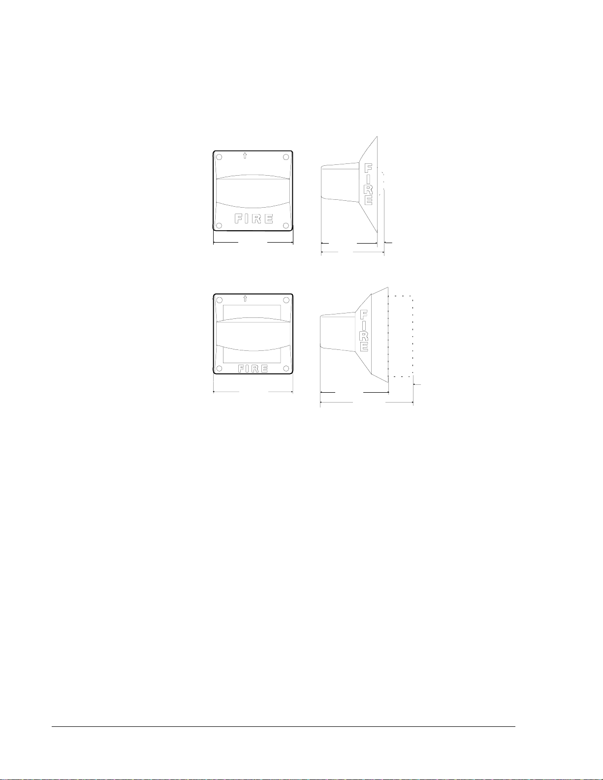
Figure 1: Dimensions
Notification Appliances—SS12/24ADA Series Strobes and MASS12/24ADA Series Sounder/Strobes 5
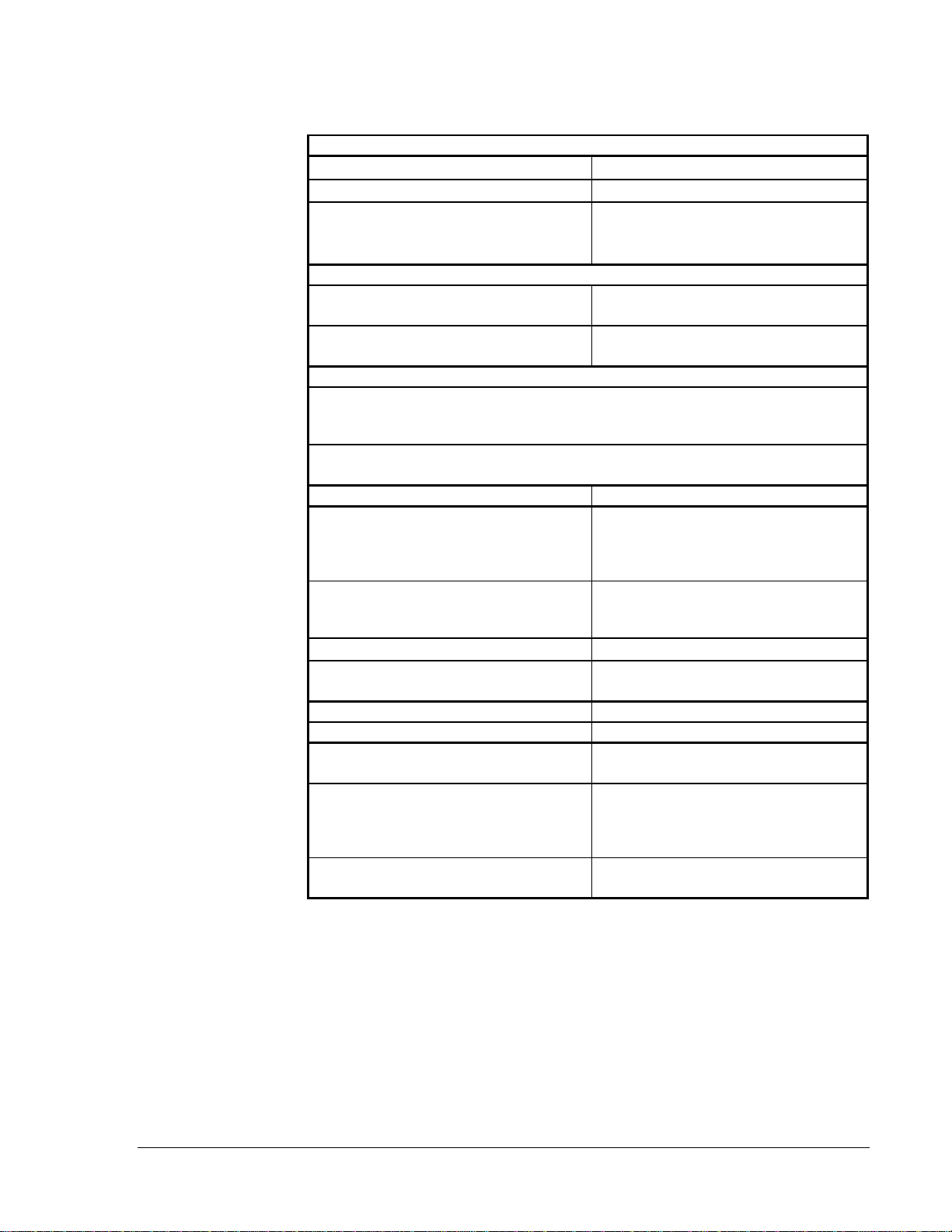
Table 1: SS12/24ADA and MASS12/24ADA Series Specifications
Mechanical
Input Terminals 12 to 18 AWG (3.31 to 0.82 mm2)
Dimensions 4 in. (101 mm) square
Front of backbox to front of unit
Front of backbox to back of unit
SS12/24ADA MASS12/24ADA
2-3/4 in. (70 mm) 3-3/4 in. (95.3 mm)
1/4 in. (6.4 mm) 1-11/32 in. (34.1 mm)
Electrical
Supply Voltage Range 10.5-17 VDC or
20-30 VDC
Operating Temperature Range 32 to 120°F (0 to 49°C); 98% maximum RH
-31 to 151°F (-35 to 66°C) MA12/24D only*
Strobe Light Ratings
The signaling strobe is rated for 0 to 49°C, and is not suitable for outdoor use.
All strobes are UL 1971 Listed. Models with outputs of 75 candela (cd) are suitable for use
in locations requiring compliance with ADA requirements.
* The MA12/24D sounder is suitable for outdoor applications when used with a WBB
weatherproof backbox.
Model Rated Light Output
SS2415ADA,
SS1215ADA,
MASS2415ADA,
MASS1215ADA,
15 cd (Figure 1)
SS121575ADA, SS241575ADA,
SS2475ADA, MASS121575ADA,
MASS241575ADA, MASS2475ADA
75 cd (Figure 1)
SS24110ADA, MASS2475ADA 110 cd (Figure 1)
SS241575ADA, SS121575ADA
MASS241575ADA, MASS121575ADA 75 cd measured at 0°viewing angle
(Figure 1)
Design Strobe Flash Rate 1 Hz
Accessories Description
BB-D 4 in. x 4 in. x 2-3/4 in. Flush Mount Deep
Backbox
MP-F, Used with SSADA models
MPF2 (RED), MPF2B (Beige)
Used with the MASSADA models
6 in. x 6 in. x 1/4 in. Flush Mounting Plate
MP-SF 6 in. x 6 in. x 1/4 in. Semi-flush Mounting
Plate

6 Notification Appliances—SS12/24ADA Series Strobes and MASS12/24ADA Series Sounder/Strobes
UL 1971 requires a polar light distribution pattern to enhance the
likelihood of alerting hearing impaired individuals throughout an area.
Figure 2 illustrates the way the standard measures light intensity, both
horizontally and vertically.
Figure 2: Vertical and Horizontal Light Dispersion
Any one of the eight sounds can be selected on the electronic sounder by
removing or adding clips to the tone selection tabs. The sound selected
determines the sound power output and the maximum current per device
as shown in the table below.
Light Distribution
lightdis.drw
Wall Mount Horizontal Light Distribution
Wall
Li
g
ht
90
45
0
-90
-45
Zero Axis
Wall
Floor
0
5
10
15
20
25
90
85 80 75 70
65 60
55 50
45 40 35 30
Wall Mount Vertical Light Distribution
De
g
rees
Percent
of Rated
Li
g
ht Output
100
90
65
48
34
27
22
18
16
15
13
12
12
12
0
5-30
35
40
45
50
55
60
65
70
75
80
85
90
De
g
rees
Percent
of Rated
Li
g
ht Output
100
90
75
55
45
40
35
35
30
30
25
25
0
5-25
30-45
50
55
60
65
70
75
80
85
90
Sound Output
Notification Appliances—SS12/24ADA Series Strobes and MASS12/24ADA Series Sounder/Strobes 7
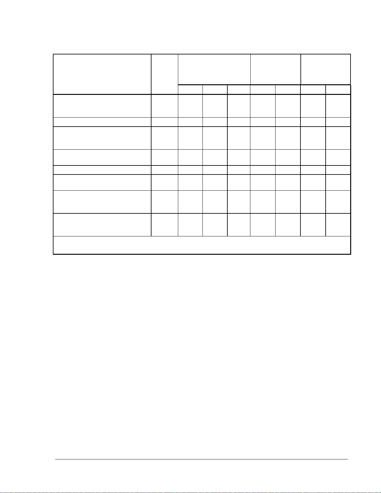
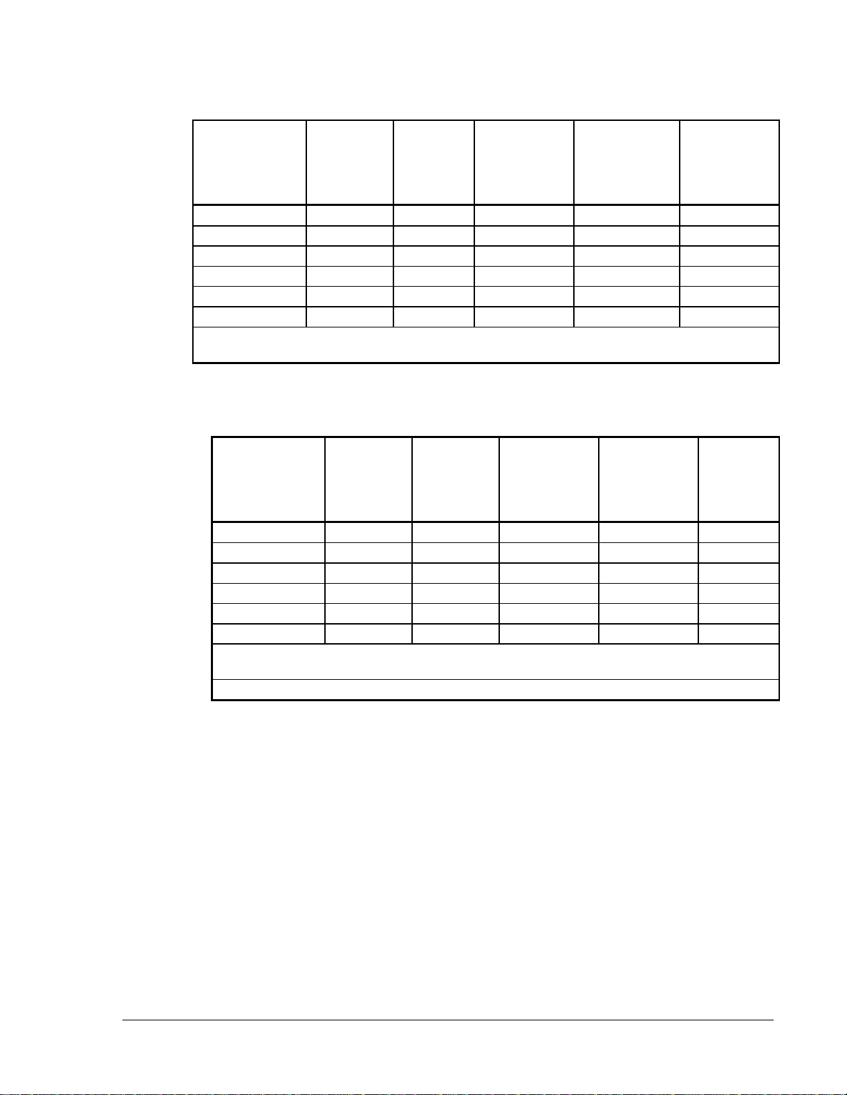
Table 2: Sound Output and Current Ratings for the MA12/24D
Sound (Hz)
Tone Description Clips on
Tabs Current (mA) Output (dBA)
in Anechoic
Chamber*
Output (dBA)
in UL
Reverberant
Room**
12V 24V 30V 12V 24V 12V 24V
Slow Whoop
800-1200 Hz Sweep in 5.0 sec/
Repeat
ABC 17 40 54 85 92 79 85
800 Hz Continuous BC 16 37 48 87 93 79 85
800/1000 Hz Alternating
800 Hz in 0.25 sec/1000 Hz in
0.25 sec/Repeat
AC 17 37 48 85 92 79 85
2400 Hz Interrupted
0.25 sec ON/0.25 sec OFF/Repeat AB 25 54 67 89 90 79 85
2400 Hz Continuous C 25556985948288
1200 Hz Interrupted
0.5 sec On/0.25 sec OFF/Repeat B 14324185917582
Swept Frequency
1200-600 Hz Sweep in 1.0 sec/
Repeat
A 16385185927985
Fast Warble
600-1200 Hz Sweep in 0.125 sec/
Repeat
none 16 37 49 85 92 79 85
* Anechoic dBA is measured on-axis in a non-reflective (free field) test room using fast meter response.
** Reverberant dBA is a minimum UL rating based on sound power measurements in a reverberant test room.
Note: The 1200 Hz interrupted tone may be used for private or public
mode in the fire alarm service when used with a 24 volt power
supply. It may be used only in the private mode when used with a
12 volt power supply.
All models can be powered using full-wave rectified, unfiltered
(unregulated) power supplies. However, if the power supply is
unregulated, the notification appliance must be compatibility listed for use
with the fire alarm system. In addition, follow the guidelines listed below:
●Under no circumstances can SS24ADA or MASS24ADA series
devices input voltage exceed 33 VDC or be less than 16 VDC peak
when using a regulated power supply. When using an unregulated
power supply, the range is 16-33 VRMS.
●Under no circumstances can the MA12/24D input voltage exceed
33 VDC or be less than 9.6 VDC.
●Under no circumstances can a SS12ADA or MASS12ADA series
device input voltage exceed 18.7 VDC or be less than 8.5 VDC for a
regulated power supply. When using an unregulated power supply,
the range is 8.5-18.7 VRMS.
8 Notification Appliances—SS12/24ADA Series Strobes and MASS12/24ADA Series Sounder/Strobes
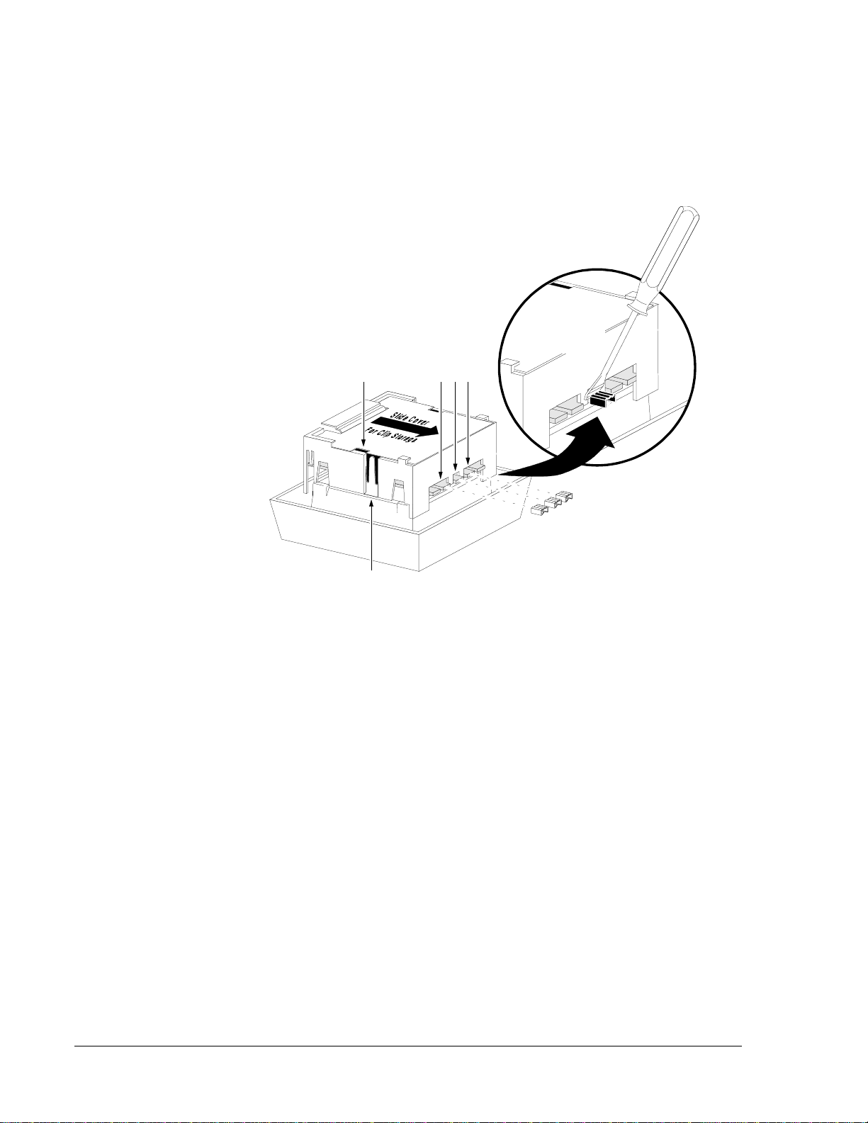
For tab clip removal and storage (Figure 3):
●Use a small bladed screwdriver to remove the clips.
●Slide the cover back to align the cover slot with the clip storage post
to store unused clips.
Remove or add clips
to select desired tone.
soundrex
Cover
Slot
A
BC
Tone
Selection Tabs
Clip
Stora
g
e
Use a small
screwdriver
to remove clips.
Figure 3: Tab Clip Removal and Storage
There may be applications where it is desirable to drive the sounder and
strobe as independent devices. The MASS12/24ADA series
sounder/strobes are easily configured for this capability. The diagram of
the terminal connection for this application is shown in Figure 13.
Independent strobe operation in an audibly-coded system requires a
separate uncoded power supply for the strobe.
Selecting Desired
Tone
Notification Appliances—SS12/24ADA Series Strobes and MASS12/24ADA Series Sounder/Strobes 9
Table 3: Operating Current from Regulated Supply
Model Number* Supply
Voltage
Range
Average
Operating
Current
(mA)
Peak Current
(mA)
20/30 VDC
Peak Current
(mA)
10.5/17 VDC
Inrush
Current
(mA in
Excess of
Peak)
SS24110ADA 20-30 VDC 210 470/500 – 0
SS2475ADA 20-30 VDC 170 385/400 – 0
SS2415ADA 20-30 VDC 75 160/180 – 0
SS1215ADA 10.5-17 VDC 170 – 360/380 0
SS241575ADA 20-30 VDC 93 210/220 – 0
SS121575ADA 10.5-17 VDC 225 – 510/560 0
* Units are available in either red or beige finish. To order red, use the model numbers listed in the table.
Add “B” suffix to end for beige.
Table 4: Operating Current from Full-Wave Rectified Unfiltered Supply
Model Number* Supply
Voltage
Range
Average
Operating
Current
(mA RMS)
Peak Current
(mA)
20/30 VDC
Peak Current
(mA)
10.5/17 VDC
Inrush
Current**
(Amperes
in Excess
of Peak)
SS24110ADA 20-30 VDC 245 400/500 – 0.080
SS2475ADA 20-30 VDC 200 320/370 – 0.040
SS2415ADA 20-30 VDC 90 275/290 – 0.020
SS1215ADA 10.5-17 VDC 200 – 330/380 0.020
SS241575ADA 20-30 VDC 120 275/290 – 1.00
SS121575ADA 10.5-17 VDC 270 – 500/530 0.030
* Units are available in either red or beige finish. To order red, use the model numbers listed in the
table. Add “B” suffix to end for beige.
** Inrush current duration is less than 20 microseconds (0.00002 seconds).
Note: Inrush current refers to current that exceeds the nominal voltage
when the strobe is first turned on. Once the strobe is turned on, it
flashes one flash per second. Peak current indicates the current
rising above the nominal voltage right after each strobe flash.

10 Notification Appliances—SS12/24ADA Series Strobes and MASS12/24ADA Series Sounder/Strobes

Notification Appliances—SS12/24ADA Series Strobes and MASS12/24ADA Series Sounder/Strobes 11
Installation Procedures
This section contains installation information for SS12/24ADA series
strobes and MASS12/24ADA series sounder/strobes. Mounting
instructions and wiring information are provided.
Installation procedures must conform to all applicable codes and the
requirements of the authority having jurisdiction.
For strobe placement, read and be familiar with:
●NFPA 72-National Fire Alarm Code, Chapter 6 (1993)
Both slotted-head and Phillips-head screws are supplied with the
speaker/strobe.
●Use the slotted-head screws to mount the device or combination of
devices on the electrical box.
●Use the Phillips-head screws in the two remaining holes when only a
speaker is being installed.
Note: The rated output of the sounder is specified at ten feet. It cannot be
assumed that the output will meet the NFPA standard of 15 dB
over ambient noise at all locations within a room. Additional
sounders may be needed to ensure that the sound output level
complies with NFPA requirements.
Strobe and sounder/strobe combination are designed for wall mounting
only.
●The sounder is 1-1/4 inches deep.
●Backboxes must be 4 inches square by at least 1-1/2 inches deep.
●2-1/8 inches deep backbox is recommended.
All strobes must be mounted where the top of the lens is 24 inches below
ceilings or as required by the authority having jurisdiction.
For mounting the sounder/strobe, note the following figures:
●Surface Mount (Figure 6)
●Semi-flush Mount (Figures 7 and 10)
General
Information
Strobe Placement
Mounting
General
Sounder/Strobe
Combination
Mounting
12 Notification Appliances—SS12/24ADA Series Strobes and MASS12/24ADA Series Sounder/Strobes
For mounting the sounder, note the following figures:
●Surface Mount (Figure 4)
●Semi-flush Mount (Figures 7 and 10)
●Flush Mount (Figure 9)
Flush mounting requires the use of the deep backbox (Part No. BB-D) or
4 inches square by 2-3/4 inches deep backbox.
1. Determine which of the two device holes will be used to attach the
device to the box.
2. Mount the flush plate to the sounder using the other two holes with
two 1-inch Phillips-head screws and two square nuts.
For mounting the sounder/strobe, note the following figures:
●Surface Mount (Figure 5)
●Semi-flush Mount (Figure 8)
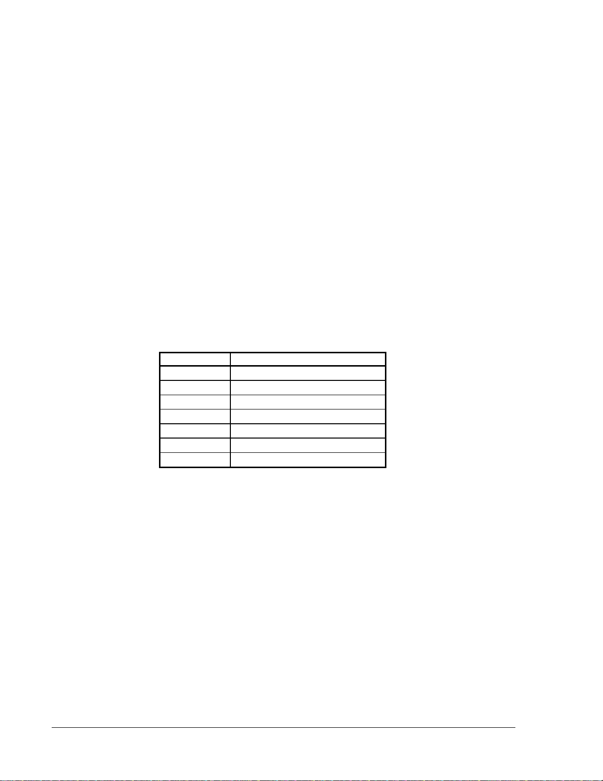
Table 5: Screw Types for Figures
Letter Screw Type
A8-32 x 1-7/16 inch Slot
BNo. 8 Sheet Metal Phillips-head
C8-32 x 1 inch Phillips-head
DNo. 8 Square Nut
E8-32 x 5/8 inch Slot
F8-32 x 2-3/4 inch Slot
G6-32 x 5/8 inch Slot
Sounder
Mounting
Strobe Mounting
Mounting Figures
Notification Appliances—SS12/24ADA Series Strobes and MASS12/24ADA Series Sounder/Strobes 13
Standard
4 inch S
q
uare
x 2-1/8 inch
Backbox
MA-12/24D
surmount
A
B
B
A
Figure 4: Sounder Surface Mount
1. Complete the field wiring as described in the Wiring Installation
Guidelines section of this technical bulletin (Figure 11).
2. Screw the sounder to the box with Type A screws.
3. Fill the remaining holes with Type B screws.
TOP
Standard
4 inch S
q
uare
x 2-1/8 inch
Backbox
surmont3
A
B
A
B
Si
g
nal Strobe
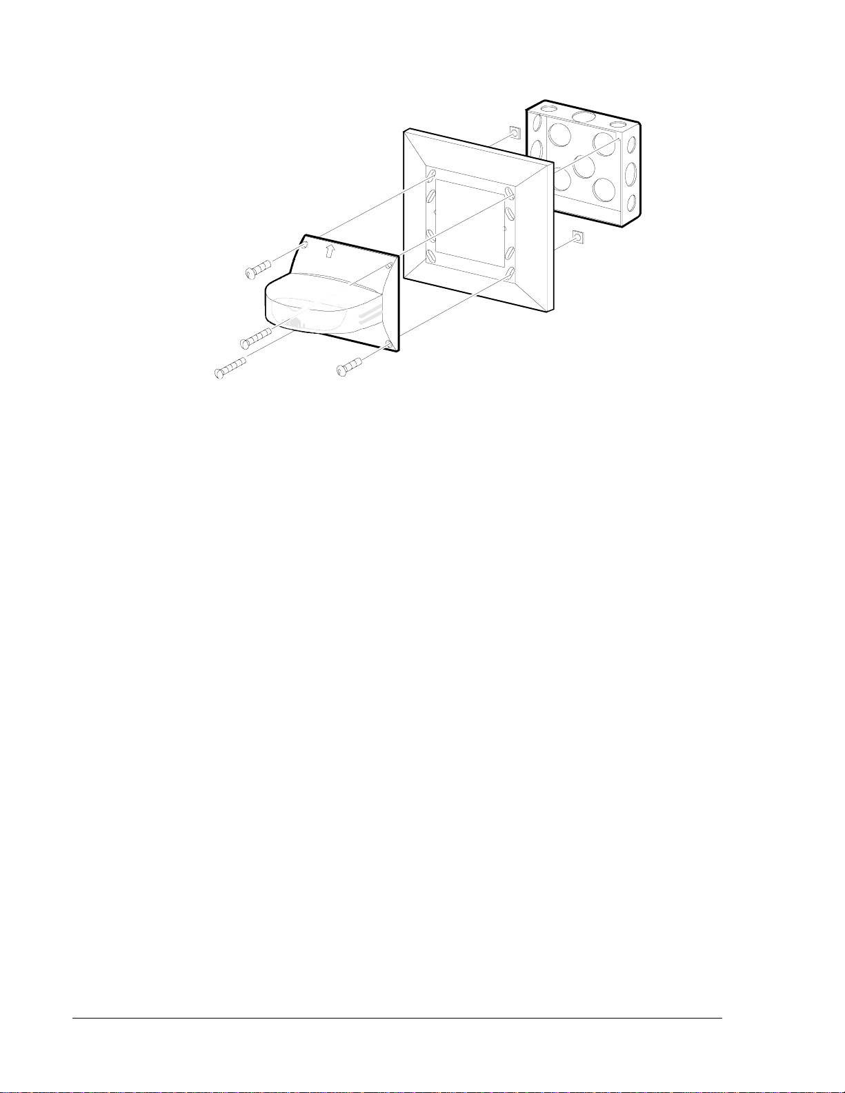
Figure 5: Strobe Surface Mount
1. Complete the field wiring as described in the Wiring Installation
Guidelines section of this technical bulletin (Figure 13).
2. Screw the strobe to the box with Type A screws.
3. Fill the remaining holes with Type B screws.

14 Notification Appliances—SS12/24ADA Series Strobes and MASS12/24ADA Series Sounder/Strobes
Figure 6: Sounder/Strobe Surface Mount
1. Complete the field wiring as described in the Wiring Installation
Guidelines section of this technical bulletin (Figures 12 and 14).
2. Screw the sounder/strobe to the box with Type A screws.
3. Fill the remaining holes with Type B screws.
Standard
4 inch S
q
uare
x 2-1/8 inch
Backbox
surmon2a
A
B
A
B
D
Si
g
nal Strobe/Sounder
TOP

Notification Appliances—SS12/24ADA Series Strobes and MASS12/24ADA Series Sounder/Strobes 15
Figure 7: Sounder or Sounder/Strobe Semi-Flush Mount
1. Add Type D nuts to the plate.
2. Screw the plate to the box with Type E screws.
3. Complete the field wiring as described in the Wiring Installation
Guidelines section of this technical bulletin (Figures 11-14).
4. Screw the sounder or sounder/strobe to the plate with Type A screws.
5. Fill the remaining holes with Type B screws.
A
B
A
B
Standard
4 inch S
q
uare
x 2-1/8 inch
Backbox
Si
g
nal Strobe/Sounder
surmont1
MP-SF
B
B
E
E
D
D
16 Notification Appliances—SS12/24ADA Series Strobes and MASS12/24ADA Series Sounder/Strobes
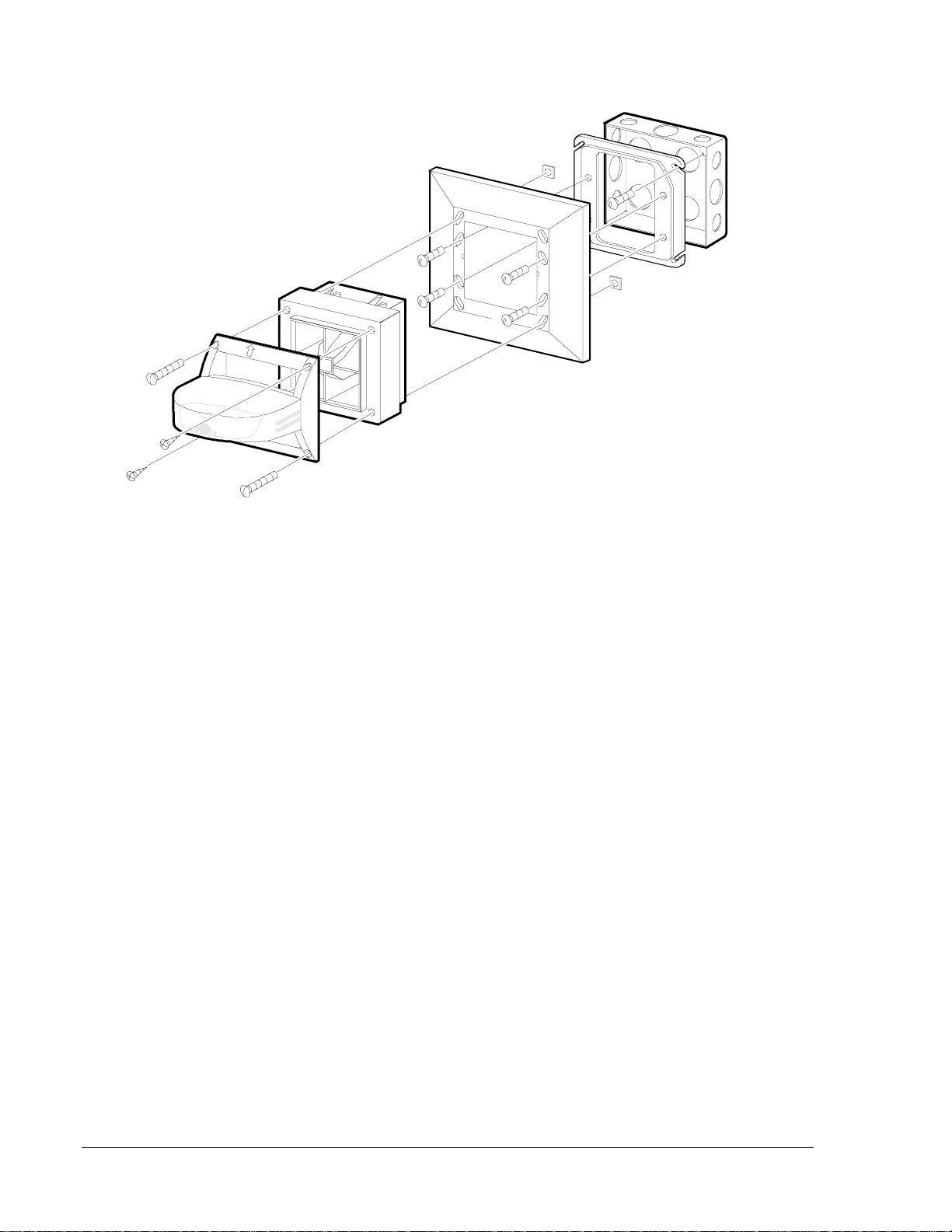
Figure 8: Strobe Semi-Flush Mount
1. Add Type D nuts to the plate.
2. Screw the strobe to the plate with Type C screws.
3. Complete the field wiring as described in the Wiring Installation
Guidelines section of this technical bulletin (Figure 13).
4. Screw the strobe-plate to the box with Type A screws.
D
D
A
TOP
A
Standard
4 inch S
q
uare
x 2-1/8 inch
Backbox
Si
g
nal Strobe
surmon11
MP-SF
C
C

Notification Appliances—SS12/24ADA Series Strobes and MASS12/24ADA Series Sounder/Strobes 17
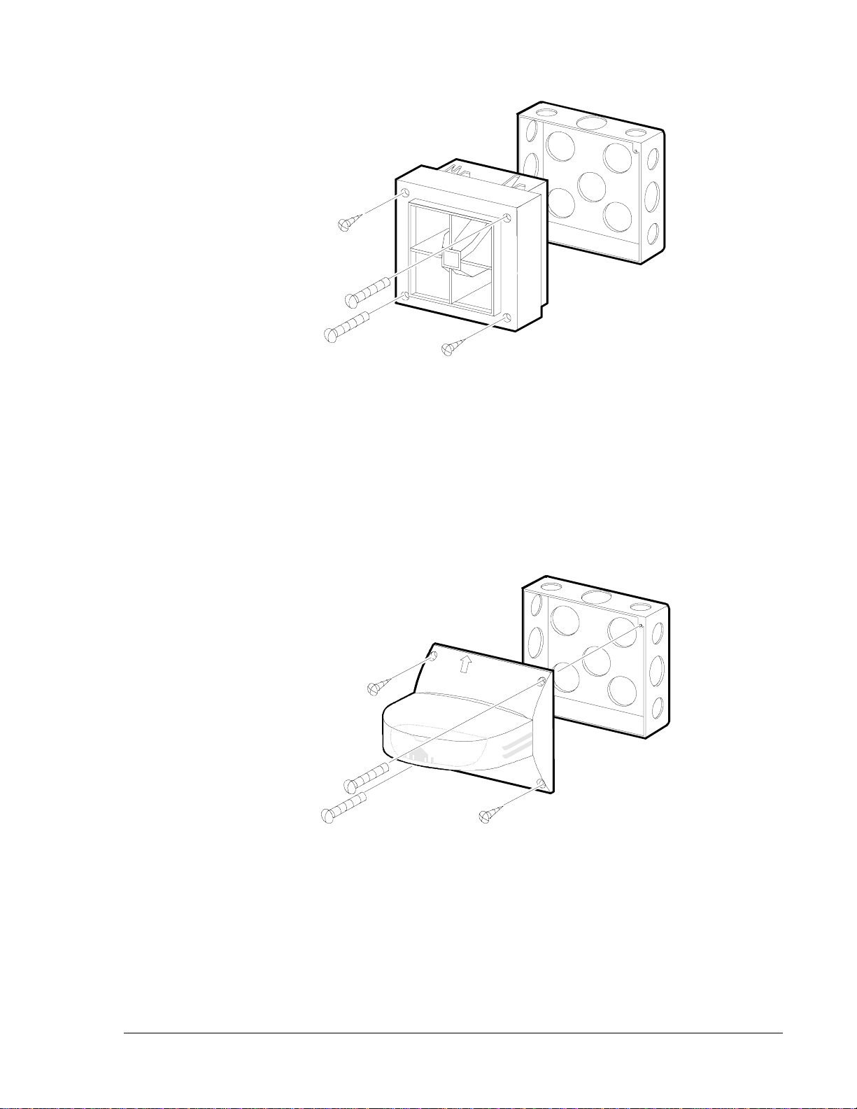
Figure 9: Sounder Flush Mount (Deep Box Required)
1. Add Type D nuts to the plate.
2. Complete the field wiring as described in the Wiring Installation
Guidelines section of this technical bulletin (Figure 11).
3. Screw the plate-sounder to the box with Type F screws.
BB-D
4 inch S
q
uare
x 2-3/4 inch
Deep Backbox
MA-12/24D
surmon12
MPF2
D
F
C
F
C
18 Notification Appliances—SS12/24ADA Series Strobes and MASS12/24ADA Series Sounder/Strobes
Figure 10: Sounder or Sounder/Strobe Semi-Flush Mount with Plaster Ring
1. The plaster ring should be properly mounted to the electrical box with
the screws supplied in the box.
2. Add Type D nuts to the plate.
3. Screw the plate to the plaster ring with Type G screws.
4. Complete the field wiring as described in the Wiring Installation
Guidelines section of this technical bulletin (Figures 11-14).
5. Screw the sounder/strobe to the plate with Type A screws.
6. To mount the sounder, fill the remaining holes with Type B screws.
7. To add the strobe to the sounder, add two Type D nuts to the sounder,
and replace Type B screws with Type C screws.
Standard
4 inch S
q
uare
x 2-1/8 inch
Backbox
surmont9
MP-SF
B
A
A
G
G
GPlaster
Rin
g
D
D
G
AC
B
A
B
TOP
Si
g
nal Strobe/Sounder

Notification Appliances—SS12/24ADA Series Strobes and MASS12/24ADA Series Sounder/Strobes 19
Note: Do not loop the Notification Appliance Circuit (NAC) wires under
the terminal screw. Wires connecting the device to the panel must
be broken at the device terminal connection in order to maintain
electrical supervision.
(
-
)
In/Out
Strobe
Onl
y
(
-
)
In/Out
(
+
)
In/Out
Strobe
Onl
y
(
+
)
In/Out
To Next
Device
or
End-of-Line
(
EOL
)
-
VDC
+
VDC
From Panel
or Previous
Device
highint1
Figure 11: Wiring the Multi-Alert Sounder
To Next
Device
or
End-of-Line
(
EOL
)
- VDC
+ VDC
From Panel
or Previous
Device
highin9
Note: Use uncoded suppl
y
onl
y
.
(
-
)
In/Out
Strobe
Onl
y
(
-
)
In/Out
(
+
)
In/Out
Strobe
Onl
y
(
+
)
In/Out
Figure 12: Wiring the Multi-Alert Sounder and Strobe
Operating in Tandem
Wiring
Installation
Guidelines
Wiring Diagrams

20 Notification Appliances—SS12/24ADA Series Strobes and MASS12/24ADA Series Sounder/Strobes
From Uncoded DC Power Suppl
y
.....
To Next Device
In
Out
In
Out
From Uncoded DC Power Suppl
y
.....
To Next Device
highin12
Floor Down
Ceilin
g
Up
Figure 13: Wiring the Strobe
To Next
Device
or
End-of-Line
(
EOL
)
-
VDC
Strobe
+ VDC
-
VDC
Sounder
+
VDC
From Panel
or Previous
Device
hi
g
hin10
Noncoded.....
Suppl
y
.....
Can be.....
Coded.....
Suppl
y
.....
CAUTION: Break off the Printed Circuit Board
(
PCB
)
tabs.
(
-
)
In/Out
Strobe
Onl
y
(
-
)
In/Out
(
+
)
In/Out
Strobe
Onl
y
(
+
)
In/Out
!
Figure 14: Wiring the Multi-Alert Sounder and Strobe
Operating Independently
This manual suits for next models
9
Table of contents
Other Metasys Marine Equipment manuals

Popular Marine Equipment manuals by other brands


Global Fire Equipment
Global Fire Equipment VALKYRIE A IP65 quick start guide

Furuno
Furuno FSV-25 MARK-2 installation manual

AML Oceanographic
AML Oceanographic AML-3 user manual

Kongsberg
Kongsberg HiPAP 502 instruction manual

Kongsberg
Kongsberg EA640 installation manual

E2S
E2S D1xS2HDC024-S instruction manual


