Pfaff 333-712/02 Guide

ADJUSTMENT MANUAL
296-12-19 289/002
adjustment Manual engl. 10.15
This instruction manual applies to machines
from the serial number 7 262 019 and
software version 0435/002 onwards.
333-712/02

Reprinting, reproduction and/or translation of PFAFF adjustment manuals
(including parts thereof) is only permitted with our prior agreement and
citation of the source.
PFAFF Industriesysteme
und Maschinen GmbH
Hans-Geiger-Str. 12 - IG Nord
D-67661 Kaiserslautern

Table of Contents
Contents ..................................................................................Page
13 Adjustment ....................................................................................................................... 5
13.01 Tools, gauges and other accessories .................................................................................... 5
13.02 Abbreviations ......................................................................................................................... 5
13.03 Explanation of symbols.......................................................................................................... 5
13.04 Adjusting basic machine ........................................................................................................ 6
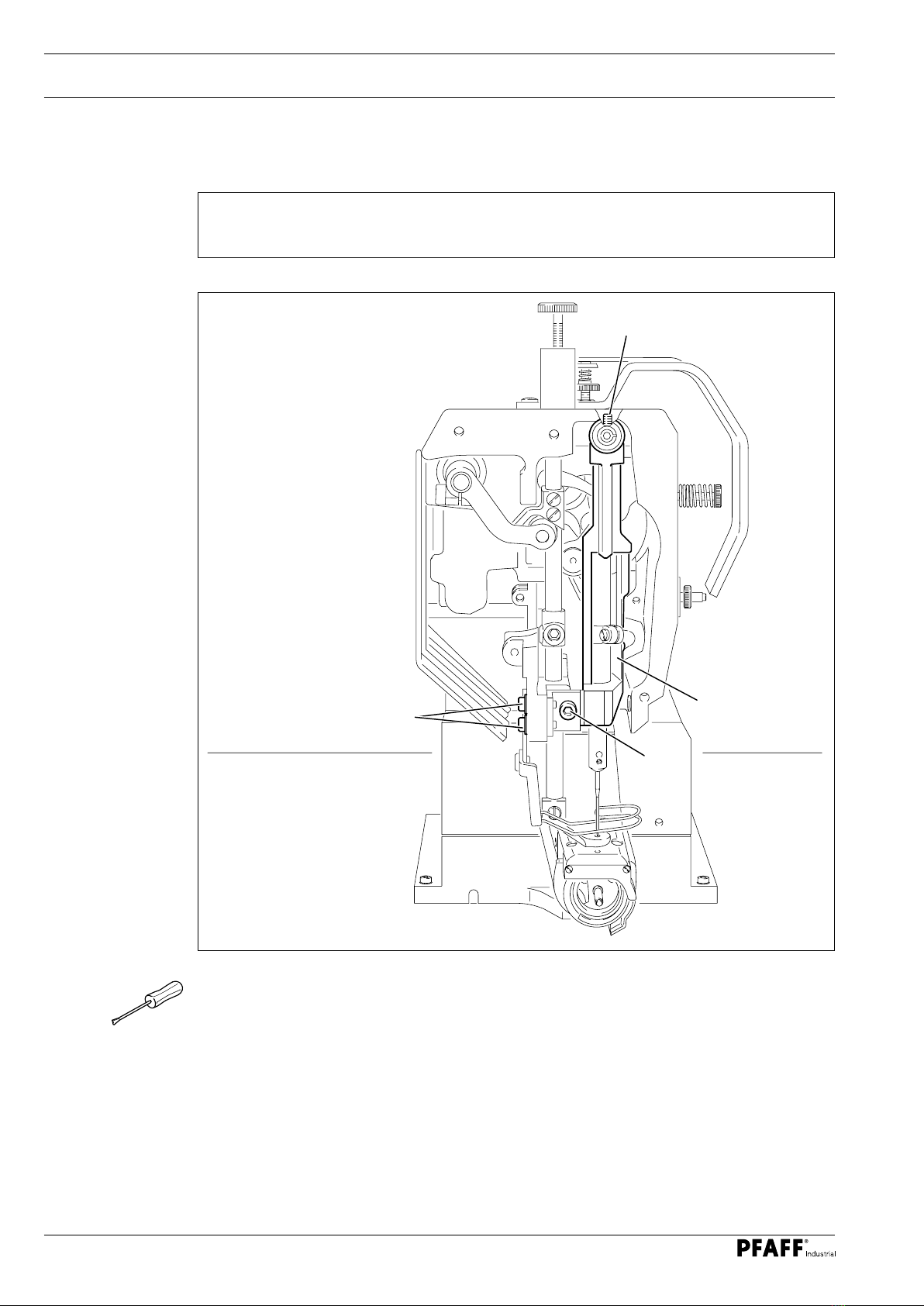
13.04.01 Needle position to needle hole .............................................................................................. 6
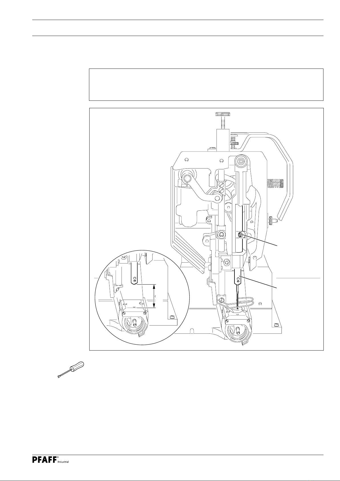
13.04.02 Needle height (pre-calibrating) ............................................................................................... 7
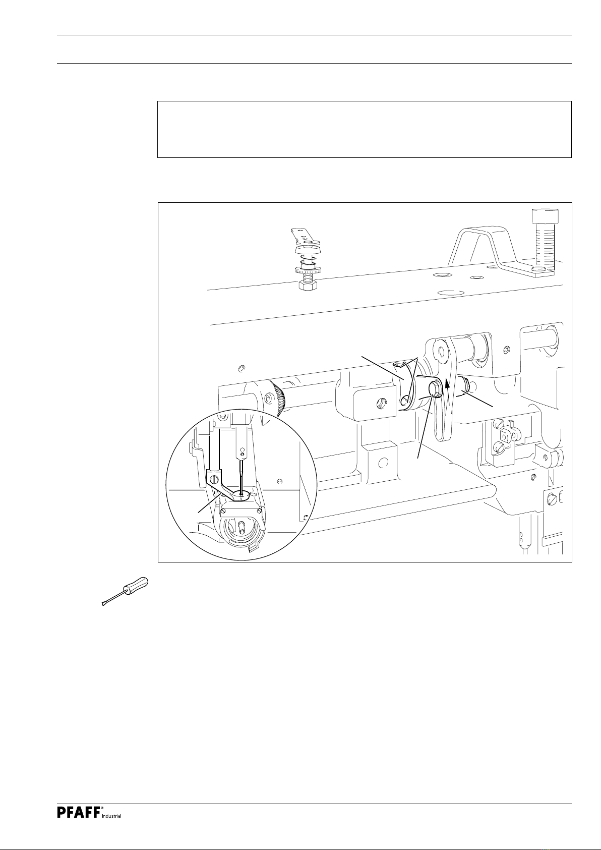
13.04.03 Hook-to-needle clearance, needle bar rise, needle height and needle guard ........................ 8
13.04.04 Presser stroke movement ..................................................................................................... 9
13.04.05 Presser stroke...................................................................................................................... 10
13.04.06 Needle thread tension release............................................................................................. 11
13.04.07 Switching off the needle thread tension release ................................................................. 12
13.04.08 Thread check spring............................................................................................................. 13
13.04.09 Bobbin winder...................................................................................................................... 14
13.04.10 Presser foot pressure .......................................................................................................... 15
13.05 Adjusting thread trimmer -900/51 .................................................................................... 16
13.05.01 Control cam (pre-calibrating) ................................................................................................ 16
13.05.02 Tripping lever height ............................................................................................................ 17
13.05.03 Feed regulator pin................................................................................................................ 18
13.05.04 Engaging solenoid................................................................................................................ 19
13.05.05 Feed regulator pin height..................................................................................................... 20
13.05.06 Front turning point of thread catcher ................................................................................... 21
13.05.07 Aligning thread catcher laterally........................................................................................... 22

Table of Contents
Contents ..................................................................................Page
13.05.08 Control cam (pre-calibrating) ................................................................................................ 23
13.05.09 Blade.................................................................................................................................... 24
13.05.10 Test cut................................................................................................................................ 25
13.06 Parameter settings ............................................................................................................. 26
13.07 Internet update of control P40 CD ...................................................................................... 26
14 Circuit Diagrams .......................................................................................................... 27

Adjustment
5
13 Adjustment
Observe and comply with all instructions in the operating manual's chapter
1 Safety! In particular make sure that all safety covers are installed again
correctly after making adjustments, see chapter 1.06 Operating manual
hazard information!
Unless otherwise stated, the machine must be disconnected from the electric
supplies before all adjustment work!
Risk of injury due to accidental machine start-up!
Notes on adjustment
All adjustments in this manual are based on a fully assembled machine and may only be car-
ried out by technical staff trained for this purpose. Machine covers, which have to be re-
moved and replaced to carry out checks and adjustments, are not mentioned in the text.
The order of the following chapters corresponds to the most logical work sequence for ma-
chines that have to be completely adjusted. Both the preceding and following chapters must
be observed if only specific individual work steps are carried out. Screws and nuts indicated
in brackets () are fastenings for machine parts, which must be loosened before any adjust-
ment and tightened again afterwards.
13.01 Tools, gauges and other accessories
O1 set of screwdrivers with blade widths from 2 to 10 mm
O1 set of wrenches with jaw widths from 7 to 14 mm
O1 set of Allen keys from 2 to 6 mm
O1 metal ruler (order no. 08-880 218-00)
ONeedle rise gauge (order no. 61-111 600-01)
OScrew clamp (order no. 61-111 600-35)
13.02 Abbreviations
t.d.c. = top dead centre
b.d.c. = bottom dead centre
13.03 Explanation of symbols
Activities to be performed or important information in this adjustment manual are empha-
sised by symbols. The symbols used have the following meaning:
Note, information
Maintenance, repairs, adjustment, service work
(only to be carried out by technical staff)

Adjustment
6
Fig. 13 - 01
2
1
13.04 Adjusting basic machine
13.04.01 Needle position to needle hole
Rule
The needle should pierce the centre of the needle hole exactly.
OLoosen the screws 1, 2 and 3.
OMove the needle directly over the needle hole by turning the handwheel.
OMove the needle bar frame 4 according to the rule.
OTighten the screws 1, 2 and 3.
4
3

Adjustment
7
Fig. 13 - 02
13.04.02 Needle height (pre-calibrating)
Rule
When the needle bar is in b.d.c., the clearance between the needle bar and stitch platen
should be 23 mm.
OAdjust the needle bar 1 (screw 2) without twisting according to the rule.
1
2
23 mm

Adjustment
8
13.04.03 Hook-to-needle clearance, needle bar rise, needle height and needle guard
Rule
With the needle rise positioned 1.8 mm after b.d.c. of the needle bar:
1. the hook point should be at the needle midpoint and have a clearance of 0.05 to
0.1 mm to the needle.
2. the upper edge of the eye of the needle should be 0.8 mm under the tip of the hook.
OLoosen screws 1 and 2 (screw 2 is located on the back of the machine).
OMove the needle bar to b.d.c. and slide the 1.8 mm thick feeler gauge with its cutout
tightly under the lower needle bar bearing. Move the screw clamp so that it touches the
feeler gauge and tighten it.
ORemove the feeler gauge and turn the handwheel in the direction of rotation until the
screw clamp rests on the needle bar bearing
OAdjust the hook on the hook shaft according to rule 1
OTurn the hook according to rule 2 (readjust the needle height if necessary), see chapter
13.04.02 Needle height (pre-calibrating).
OMove the hook shaft bearing 3 until it abuts the hook and tighten the screw 2.
OMove the bevel gear 4 until it abuts the bearing 5 and tighten the screws 1.
The setting of the end play of the hook shaft and hook shaft bearing 3 is
omitted in machines with thread trimmer -900/51.
Fig. 13 - 03
12
13
5
4
0.05 - 0.1 mm
0.8 mm

Adjustment
9
13.04.04 Presser stroke movement
Rule
The presser foot 3 and the tip of the needle should reach the stitch platen at the same
time when turning the handwheel.
OSlide the lever 1 (screw 2)in its slotted lever until you feel it reach the upper stop.
OLower the presser foot 3 onto the stitch platen.
OLoosen the screws 4 until the eccentric 5 is difficult to turn on the shaft.
OTurn the eccentric 5 according to the rule.
OTighten the screws 4.
Fig. 13 - 04
1
2
54
3

Adjustment
10
13.04.05 Presser stroke
Rule
1. When the needle bar is in b.d.c., there should be a clearance of 172 mm between the
clamp 1 and the stitch platen.
2. The presser foot 5 should lift 20 mm off the stitch platen in its upper turning point at
maximum stroke adjustment.
Fig. 13 - 05
OMove the needle bar to b.d.c.
OAdjust the clamp 1 (screws 2) according to rule 1.
OSlide the lever 3 (screw 4) in its slotted lever until you feel it reach the upper stop.
OMove the presser foot 5 to its upper turning point by turning the handwheel.
OTurn the crank 6 (screw 7) according to rule 2.
20 mm
172 mm
1
2
5
4
3
6
7

Adjustment
11
13.04.06 Needle thread tension release
Rule
1. The tension discs should start to open with the thread lever positioned 10 mm before
t.d.c.
2. When the thread lever is at t.d.c., there should be a clearance of 1.0 mm between the
tension discs.
OAdjust the thread lever to a position 10 mm before t.d.c.
OTurn the eccentric 1 (screws 2) according to rule 1.
OTurn the handwheel until the tension discs are at the maximum distance from each
other.
OMove the thread tension (screw 3) according to rule 2.
Fig. 13 - 06
2
1
1.0 mm
3

Adjustment
12
Fig. 13 - 07
13.04.07 Switching off the needle thread tension release
OTurn the handwheel until the tension discs are closed.
OAlign the lever 1 according to rule 1.
OTurn the stop 2 (nut 3) according to rule 2.
The magnet lift is factory set to 1 mm.
Setting on the nut 5 (lock nut 6).
Rule
1. There should be a clearance of approx. 0.5 mm between the lever 1 and the tension
disc 4 when the tension discs are closed.
2. The nut 5 should abut the stop 2 in the basic position of the solenoid 7.
0.5 mm
2
1
3
4
5
7
7
6
1

Adjustment
13
Fig. 13 - 08
2
1
3
4
13.04.08 Thread check spring
OAdjust the stop 1 (screw 2) according to the rule.
OTurn the screw 3 (screw 4) to set the spring tension
The length of the thread check spring deflection may deviate slightly upwards
and downwards for reasons relating to the sewing technology.
Rule
The movement of the thread check spring 5 should be finished when the needle point
punctures the material (spring deflection = approx. 7 mm).
5
7 mm

Adjustment
14
1
2
5
Fig. 13 - 09
13.04.09 Bobbin winder
Rule
1. When the bobbin winder is switched on, the bobbin winder spindle should be moved
easily; when the bobbin winder is switched off, the friction wheel 5 must not touch
the drive wheel 1.
2. The bobbin winder should switch off automatically when the fill amount is still around
1 mm from the edge of the bobbin.
OAdjust the drive wheel 1 (screws 2) according to rule1.
OAdjust the stud 3 (screws 4) according to rule 2.
3
4
1 mm

Adjustment
15
Fig. 13 - 10
13.04.10 Presser foot pressure
Rule
The material should be transported properly even at top sewing speed.
No pressure marks should appear on the material.
OTurn the screw 1 according to the rule.
1

Adjustment
16
Fig. 13 - 11
13.05 Adjusting thread trimmer -900/51
13.05.01 Control cam (pre-calibrating)
Rule
When the needle bar is in b.d.c., the groove 4 of the control cam 2 should stand vertical
under the feed regulator pin 5.
OLoosen the screws 1 through the hole in the machine housing.
OMove the thread lever to b.d.c.
OTurn the control cam 2 according to the rule.
OMove the control cam 2 down so that it touches the bearing 3 and tighten
the accessible screw 1.
OMake the second screw 1 accessible and tighten it.
2
1
2
4
3
5

Adjustment
17
Fig. 13 - 12
13.05.02 Tripping lever height
Rule
When the needle bar is in b.d.c., there should be a clearance of 1.0 mm between the
tripping lever 3 and the control cam 4.
OMove the needle bar to b.d.c.
OAdjust the carrier 1 (screws 2) of the tripping lever 3 in the elongated hole according to
the rule.
1
2
4
1 mm
3

Adjustment
18
Fig. 13 - 13
13.05.03 Feed regulator pin
Rule
When the needle bar is in b.d.c., the feed regulator pin 5 should be able to drop easily
into the control cam track 7 when the engaging solenoid 6 is activated.
OMove the needle bar to b.d.c.
OActivate the field core 1 manually.
OTurn the screw 2 (nut 3) until it slightly touches the tripping lever 4.
OLoosen the screw 2 approx. half a rotation until the movement of the
feed regulator pin 5 complies with the rule.
1
6
3
4
2
5
7

Adjustment
19
Fig. 13 - 14
13.05.04 Engaging solenoid
Rule
When the needle bar is in b.d.c., and the field core 1 is activated up to the stop, there
should be a clearance of approx. 0.5 mm between the pawl 4 and the retaining collar 5.
OMove the needle bar to b.d.c.
OSlide the field core 1 up to the stop.
OAdjust the magnet housing 2 (screw 3) according to the rule.
1
35
24
0.5 mm

Adjustment
20
Fig. 13 - 15
13.05.05 Feed regulator pin height
Rule
When the thread trimmer is in the neutral position and the pawl 4 is engaged, there
should be a clearance of 0.3 mm between the highest point of the control cam 5 and the
feed regulator pin 6.
OMove the needle bar to t.d.c.
OActivate the field core 1.
OAdjust the retaining collar 2 (screws 3) according to the rule.
14 3
2
5
6
0.3 mm
Other manuals for 333-712/02
4
Table of contents
Other Pfaff Sewing Machine Accessories manuals
Popular Sewing Machine Accessories manuals by other brands

ELNA
ELNA 202-080-202 quick start guide

DURKOPP ADLER
DURKOPP ADLER 867 instructions

Racing
Racing MCA 20K-38/TR Installation Guide book

Hinterberg Design
Hinterberg Design Machine quilting frame instructions

Bernina
Bernina Medium Clamp Embroidery Hoop quick start guide

Arrow
Arrow NORMA JEAN 350 owner's manual