Pfaff 5625-657/01 User manual

Instruction Manual
5625
296-12-18933/002
Betriebsanleitung engl. 01.06
This instruction manual applies to machines from the
following serial numbers onwards:
# 2731762
-657/01
-657/02

This instruction manual applies to all versions and subclasses listed under
"Specifications".
Reprinting, copying or translation of PFAFF instruction manuals, whether in whole or in part,
is not permitted without our prior permission and not without written indication of the
source.
PFAFF Industrie Maschinen AG
Postfach 3020
D-67653 Kaiserslautern
Königstr. 154
D-67655 Kaiserslautern

Contents
Contents ................................................................................. Chapter - Page
1Safety ........................................................................................................ 1 - 1
1.01 Directives ...................................................................................................................... 1 - 1
1.02 General notes on safety ................................................................................................ 1 - 1
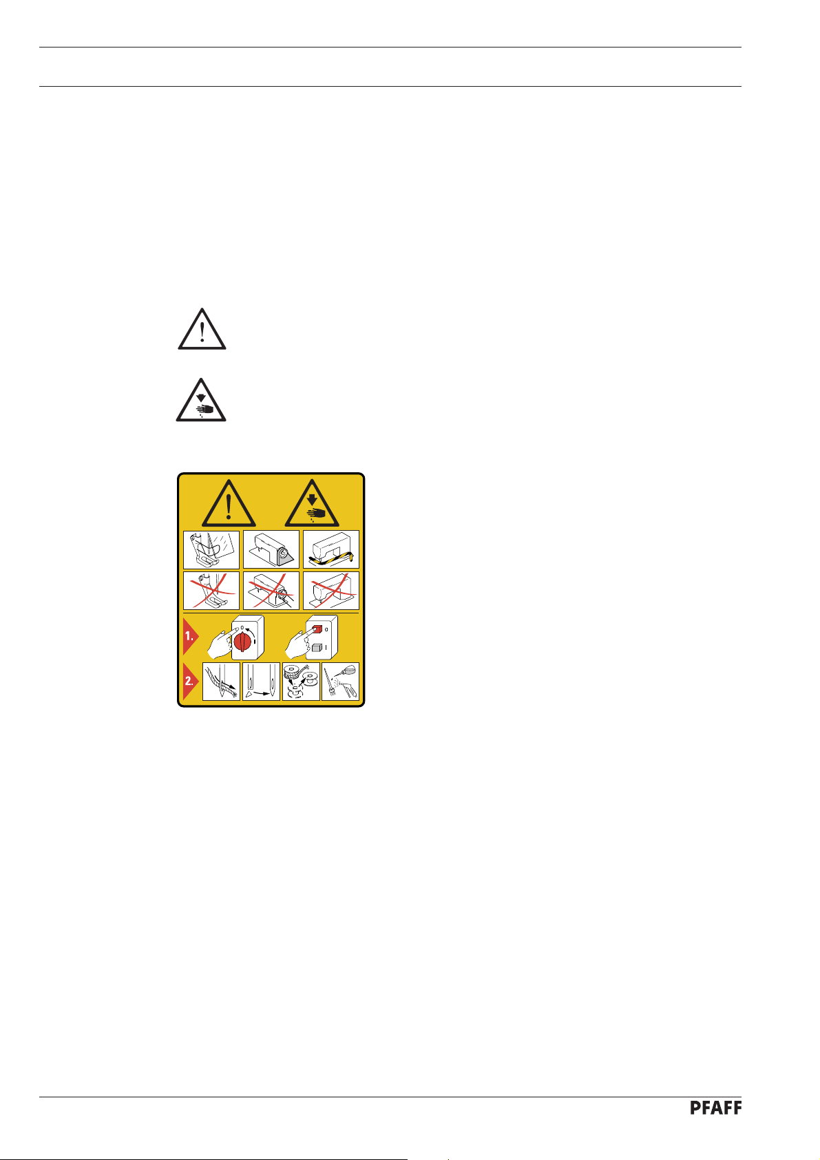
1.03 Safety symbols ............................................................................................................. 1 -2
1.04 Important points for the user ........................................................................................ 1 - 2
1.05 Operating and specialist personnel ............................................................................... 1 - 3
1.05.01 Operating personnel ...................................................................................................... 1- 3
1.05.02 Specialist personnel ......................................................................................................1- 3
1.06 Danger .......................................................................................................................... 1 - 4
2Proper use .................................................................................................. 2 - 1
3Specifications ............................................................................................. 3 - 1
4Disposal of the machine ............................................................................... 4 - 1
5Transport, packaging and storage ................................................................. 5 - 1
5.01 Transport to the customer ............................................................................................ 5 - 1
5.02 Transport within the customer’s premises ................................................................... 5 - 1
5.03 Disposal of the packaging ............................................................................................. 5 - 1
5.04 Storage ......................................................................................................................... 5 - 1
6Explanation of the symbols .......................................................................... 6 - 1
7Controls ....................................................................................................................... 7- 1
7.01 Adjusting the stitch length ............................................................................................ 7 - 1
7.02 Adjusting the top feed stroke on the PFAFF 5625-657/01 ............................................. 7 - 1
7.03 Adjusting the top feed stroke on the PFAFF 5625-657/02 ............................................. 7 - 2
7.04 Lifting the presser foot .................................................................................................. 7 - 2
7.05 Key for fixing the presser foot ....................................................................................... 7 - 3
8Installation and commissioning ................................................................................. 8 - 1
8.01 Installation ..................................................................................................................... 8 - 1
8.02 Commissioning ............................................................................................................. 8 - 1
9Setting up .................................................................................................................... 9 -1
9.01 Inserting the needle ...................................................................................................... 9 - 1
9.02 Threading the machine / adjusting the thread tension ................................................... 9 - 2
10 Care and Maintenance .............................................................................................. 10 - 1
10.01 Cleaning the looper compartment ............................................................................... 10 - 1
10.02 Checking the oil level / filling in oil ............................................................................... 10 - 2
10.03 Checking the oil level in the oil tank for the needle head parts / filling in oil ................ 10 - 3

Contents
Contents ................................................................................. Chapter - Page
11 Adjustment ................................................................................................................ 11 - 1
11.01 Notes on adjustment................................................................................................... 11 - 1
11.02 Tools, gauges and other accessories .......................................................................... 11 - 1
11.03 Abbreviations .............................................................................................................. 11- 1
11.04 Adjusting the basic machine ....................................................................................... 11 - 2
11.04.01 Needle height (preliminary adjustment) ....................................................................... 11 - 2
11.04.02 Driving eccentric of the looper (Pre-adjust) ................................................................. 11 - 3
11.04.03 Feed lifting eccentric ................................................................................................... 11 - 4
11.04.04 Driving eccentric of the spreader ................................................................................ 11 - 5
11.04.05 Feed driving eccentric and drive to needle bar frame .................................................. 11 - 6
11.04.06 Positioning the feed dog ............................................................................................. 11 - 7
11.04.07 Feed dog height .......................................................................................................... 11 - 8
11.04.08 Position of the needle to the needle hole .................................................................... 11 - 9
11.04.09 Position of the looper crosswise to the sewing direction ............................................ 11 - 10
11.04.10 Position of the looper in the direction of sewing / re-adjusting the looper eccentric ........ 11 - 11
11.04.11 Readjusting the needle height ..................................................................................... 11 - 12
11.04.12 Position of the spreader in the direction of sewing ..................................................... 11 - 13
11.04.13 Position of the spreader crosswise to the direction of sewing .................................... 11 - 14
11.04.14 Needle guard and thread loop support ........................................................................ 11 - 15
11.04.15 Balancing weight ......................................................................................................... 11 - 16
11.04.16 Feed difference ...........................................................................................................11-17
11.04.17 Top feed stroke on the PFAFF 5625-657/01 ................................................................ 11 - 18
11.04.18 Top feed stroke on the PFAFF 5625-657/02 ................................................................ 11 - 19
11.04.19 Limiting the top feed stroke ........................................................................................ 11 - 20
11.04.20 Lifting motion of the top feed dog ............................................................................... 11 - 21
11.04.21 Clearance between the presser foot and the needle plate .......................................... 11 - 22
11.04.22 Presser foot-to-needle plate clearance on the PFAFF 5625-657/02 ............................. 11 - 23
11.04.23 Needle thread tension release (only on the PFAFF 5625-657/01) ................................ 11 - 24
11.04.24 Needle thread regulator and take-up lever guard......................................................... 11 - 25
11.04.25 Looper thread regulator ............................................................................................... 11 - 26
11.04.26 Limiting the stitch length............................................................................................. 11 -27

Safety
1 - 1
1 Safety
1.01 Regulations
This machine is constructed in accordance with the European regulations indicated in the
conformity and manufacturer's declarations.
In addition to this instruction manual, please also observe all generally accepted, statutory
and other legal requirements, including those of the user's country, and the applicable pol-
lution control regulations!
The valid regulations of the regional social insurance society for occupational accidents or
other supervisory authorities are to be strictly adhered to!
1.02 General notes on safety
●The machine must only be operated by adequately trained operators and only when the
instruction manual has been fully read and understood!
●All notices on safety and the instruction manual of the motor manufacturer are to be read
before the machine is put into operation!
●All notes on the machine concerning danger and safety must be observed!
●The machine must be used for the purpose for which it is intended and must not be
operated without its safety devices; all regulations relevant to safety must be adhered to.
●When part sets are changed (e.g. needle, presser foot, needle plate, feed dog or bob-bin),
during threading, when the workplace is left unattended and during maintenance work,
the machine must be disconnected from the power supply by turning off the on/off
switch or removing the plug from the mains!
●Daily maintenance work must only be carried out by appropriately trained persons!
●Repairs and special maintenance work must only be carried out by qualified technical
staff or persons with appropriate training!
●During maintenance or repairs on the pneumatic system the machine must be
disconnected from the compressed air supply! The only exception to this is when
adjustments or function checks are carried out by appropriately trained technical staff!
●Work on the electrical equipment must only be carried out by technical staff who are
qualified to do so!
●Work on parts or equipment connected to the power supply is not permitted! The only
exceptions to this are specified in regulations EN 50110.
●Conversion or modification of the machine must only be carried out under observation of
all relevant safety regulations!

Safety
1 - 2
●Only spare parts which have been approved by us are to be used for repairs! We draw
special attention to the fact that spare parts and accessories not supplied by us have not
been subjected to testing nor approval by us. Fitting and/or use of any such parts may
cause negative changes to the design characteristics of the machine. We shall not ac-
cept any liability for damage caused by the use of non-original parts.
1.03 Safety symbols
Danger!
Special points to observe.
Danger of injury to operating or technical staff!
I
1.04 Important notes for the user
●This instruction manual belongs to the equipment of the machine and must be available
to the operating staff at all times.
This instruction manual must be read before the machine is operated for the first time.
●Both operating and technical staff must be instructed on the safety devices of the mach-
ine and on safe working methods.
●It is the duty of the user to operate the machine in perfect running order only.
●The user must ensure that none of the safety devices are removed nor put out of work-
ing order.
●The user must ensure that only authorized persons operate and work on the machine.
For further information please refer to your PFAFF agency.
Caution
Do not operate without finger guard and safety devices.
Before threading, changing bobbin and needle, cleaning
etc. switch off main switch.

Safety
1 - 3
1.05 Notes for operating and technical staff
1.05.01 Operating staff
Operating staff are the persons responsible for setting up, operating and cleaning the mach-
ine and for removing any disturbances in the sewing area.
The operating staff are obliged to observe the following points, and must:
●always observe the notes on safety in this instruction manual!
●avoid using any working methods which adversely effect the safety of the machine!
●avoid wearing loose-fitting clothing or jewelry such as necklaces or rings!
●also ensure that only authorized persons are allowed near the danger area of the
machine!
●immediately report to the user any changes to the machine that may affect its safety!
1.05.02 Technical staff
Technical staff are persons who have been trained in electrical engineering, electronics,
pneumatics and mechanical engineering. They are responsible for lubricating, servicing,
repairing and adjusting the machine.
The technical staff are obliged to observe the following points, and must:
●always observe the notes on safety in this instruction manual!
●switch off the on/off switch before carrying out adjustment and repair work and ensure it
cannot be switched on again unintentionally!
●never work on parts or equipment still connected to the power supply! Exceptions to this
are only permissible according to regulations EN 50110;
●disconnected the machine from the compressed air supply when carrying out
maintenance or repair work on pneumatic equipment!
Exceptions to this are only permissible for function checks;
●replace all safety covers after carrying out maintenance or repair work!

Safety
1 - 4
1.06 Danger warnings
A working area of 1 m must be kept free both in front of and behind the mach-
ine, so that easy access is possible at all times.
Never put your hands in the sewing area during sewing!
Danger of injury by the needle!
While setting or adjusting the machine do not leave any objects on the table nor
in the needle plate area! Objects may be trapped or slung out of the mach-ine!
Fig. 1 - 01
2
1
Do not operate the machine without take-up lever guard 1!
Danger of injury from the movement of the take-up lever!
Do not operate the machine without a belt guard!
Danger of injury by running drive belts!
Do not operate the machine without finger guard 2!
Danger of injury by the needle!

Proper use
2 - 1
2 Proper use
The PFAFF 5625-657/01
is a single-needle, lockstitch special sewing machine with unison
feed and pneumatically adjustable lift stroke.
The PFAFF 5625-657/02
is a single-needle, lockstitch special sewing machine with unison
feed and mechanically adjustable lift stroke.
Any use of these machines which is not approved by the manufacturer shall be
considered as improper use! The manufacturer shall not be liable for any dam-
age arising out of improper use! Proper use shall also be considered to include
compliance with the operation, adjustment, service and repair measures speci-
fied by the manufacturer!

Specifications
3 - 1
3 Specifications▲
Stitch type: ................................................................................................ 401 (chainstitch)
Version: .................................................................................................................... C N8,5
Needle size: ..........................................................................................................150 - 180
Needle system: .................................................................................................... 5640-59R
Max. thread size: .......................................................................................................... 11/3
(Synthetic or comparable sizes of other thread types)
Effective balance wheel Ø: ....................................................................................... 80mm
Presser foot clearance: ............................................................................................ 11 mm
Clearance width: .................................................................................................... 255 mm
Clearance height: ................................................................................................... 112 mm
Max. stitch length: .................................................................................................. 8,5 mm
Noise data:
Emission sound level at the workplace ............................. (see equipment service manual)
Air consumption per switch cycle: ......................................................................... 0.146 Nl
Net weight machine head: ............................................................................. approx. 56 kg
Gross weight: ................................................................................................. approx. 64 kg
▲ Subject to alterations in design, weight and dimensions
Maximum sewing speed
The maximum sewing speed depends on the material to be sewn, and thus on the top feed
stroke.
Chaining off speed
To minimize noices when chaining off, we recommend to reduce the possible
maximum speed.
3.01 Possible work aids
Sub-class –906/07 ................................................... pneumatic foot lift and tension release
Top Max. speed Top Max. speed
feed in s.p.m. feed in s.p.m.
1 mm 4000 5 mm 2200
2 mm 3600 6 mm 2000
3 mm 3000 7 mm 1800
4 mm 3000

Disposal of Machine
4 - 1
4 Disposal of Machine
●Proper disposal of the machine is the responsibility of the customer.
●The materials used for the machine are steel, aluminium, brass and various plastic mat-
erials.
The electrical equipment comprises plastic materials and copper.
●The machine is to be disposed of according to the locally valid pollution control regula-
tions; if necessary, a specialist ist to be commissioned.
Care must be taken that parts soiled with lubricants are disposed of separately
according to the locally valid pollution control regulations!

Transport, packaging and storage
5 - 1
5 Transport, packaging and storage
5.01 Transportation to customer's premises
All machines are delivered completely packed.
5.02 Transport within the customer’s premises
The manufacturer bears no liability for transport within the customer’s premises or to the in-
dividual locations of use.
Always ensure that the machine is only transported upright.
5.03 Disposal of the packaging
The packaging of these machines consists of paper, cardboard and VCE fiber. The proper
disposal of the packaging is the responsibility of the customer.
5.04 Storage
The machine can be stored for up to 6 months if not in use. During this time it should be
protected from dust and moisture.
For longer storage the individual parts of the machine, especially the moving parts, should be
protected agains corrosion, e.g. by a film of oil.

Explanation of the symbols
16 - 1
6 Explanation of the symbols
In this Instruction Manual, tasks to be carried out and important information are drawn to
your attention by symbols. The symbols have the following meanings:
Note, information
Cleaning, care
Lubrication
Servicing, repairing, adjustment, maintenance
(only to be carried out by specialist personnel)

Controls
7 - 1
6
2-
05
1
7 Controls
7.01 Adjusting the stitch length
●After pressing key 1, the required stitch
length can be set by turning adjustment
wheel 2.
Fig. 7 - 01
7.02 Adjusting the top feed stroke on the PFAFF 5625-657/01
●The top feed stroke can be set by turning
adjustment wheel 1.
The maximum top feed stroke
is limited by the manufacturer.
The limit can be changed by
qualified personnel, see
Chapter 11.04.17 Top feed
stroke.
Fig. 7 - 02
2
1
62-004
1

Controls
7 - 2
7.03 Adjusting the top feed stroke on the PFAFF 5625-657/02
Maschine ausschalten!
Verletzungsgefahr durch unbe-
absichtigtes Anlaufen der Ma-
schine!
●Open cover on the rear side of the
machine, loosen nut 1and adjust lever 2
accordingly
Fig. 7 - 03
1
62-022
Fig. 7 - 04
7.04 Lifting the presser foot
●The presser foot can be lifted by
operating lever 1.
On machines with
pneumatically-operated foot lift
(sub-class –906/07) the presser
foot can be lifted as described
in the system service manual.
1
2

Controls
7 - 3
62-003
Fig. 7 - 05
7.05 Key for fixing the presser foot
●The presser foot can be fixed by raising
it, then pressing key 1and lowering the
presser foot.
●To release it raise the presser foot.
1
Further control elements are described in the system service manual.

Installation and commissioning
8 - 1
8 Installation and commissioning
The machine must only be installed and commissioned by qualified personnel!
It is imperative that all relevant safety regulations are observed!
8.01 Installation
●Suitable connections for electricity must be available at the machine’s location.
●Make sure that a level and firm surface as well as sufficient lighting are guaranteed at the
machine’s location.
●Connect the ground cable from the sewing head, motor, main switch and additional units
to the frame, see the system service manual.
8.02 Commissioning
●The machine, in particular the electric cables and pneumatic connection tubes must be
checked for damage.
●Clean the machine thoroughly and then, with the machine in its assembly position, fill
in oil, see Chapter 10 Care and Maintenance.
●When the machine is running, the balance wheel must turn towards the operator. If this
is not the case, have the machine converted by specialized staff.

9 - 1
Setting up
62-005
9 Setting up
All regulations and instructions in this service manual must be observed.
Special attention must be paid to all safety regulations!
All setting up work is only to be carried out by appropriately trained personnel.
For all setting up work the machines must be disconnected from the mains by
operating the main switch or by pulling out the plug.
9.01 Inserting the needle
Switch off the machine!
Danger of injury if the machine
is started accidentally!
Only use needles from the
system intended for the
machine, see Chapter 3
Specifications.
●Raise the needle bar to its highest
position and loosen screw 1
..
..
.
●Insert needle 2as far as possible into the
needle bar (the long needle groove must
be facing right).
●Tighten screw 1.
Fig. 9 - 01
1
2

9 - 2
Setting up
3
--
--
-+
Fig. 9 - 02
62-023
2
1
9.02 Threading the machine / adjusting the thread tensions
Switch off the machine!
Danger of injury if the machine is started accidentally!
●Thread the needle thread as shown in Fig. 9-02.
●Adjust the needle thread tension by turning milled screw 1.
●Open the top and side cover of the looper compartment.
●Thread the looper thread as shown in Fig. 9-02.
●Insert the thread on the looper 2with a pair of tweezers.
●Adjust the looper thread tension by turning milled screw 3.

Care and Maintenance
10 - 1
The maintenance intervals apply to an average machine running time for a
single shift. Shorter maintenance intervals are advisable for longer running
times.
10.01 Cleaning the looper compartment
Switch off the machine.
Danger of injury if the machine is started accidentally!
●Clean the complete looper and looper compartment daily, several times if in continuous
use.
10 Care and Maintenance
Clean the looper compartment............ daily, several times when in continuous operation
Clean the entire machine .............................................................................. once a week
Check the gear oil level ............................................................................ daily before use
Check the oil level in the oil tank for the needle head parts. .................... daily before use
Other manuals for 5625-657/01
1
This manual suits for next models
1
Table of contents
Other Pfaff Sewing Machine manuals

Pfaff
Pfaff hobbylock 4842 User manual

Pfaff
Pfaff smart 100s User manual

Pfaff
Pfaff creative 1469 User manual

Pfaff
Pfaff COVERLOCK 4.0 - User manual

Pfaff
Pfaff 76 User manual

Pfaff
Pfaff SZA-645F User manual

Pfaff
Pfaff 3734-12 User manual

Pfaff
Pfaff 463 User manual

Pfaff
Pfaff 3588-05/020 User manual

Pfaff
Pfaff 3538-20/02 Guide