Pfaff Powerline 2545 Guide

This Adjustment Manual is valid for machines
from the following serial numbers onwards:
# 2 798 767
296-12-19 220/002
Justieranleitung engl. 06.13
ADJUSTMENT MANUAL
2545
2546

The reprinting, copying or translation of PFAFF Service Manuals, whether in whole or in part,
is only permitted with our previous authorization and with written reference to the source.
PFAFF Industriesysteme
und Maschinen AG
Hans-Geiger-Str. 12 - IG Nord
D-67661 Kaiserslautern

Index
Contents ................................................................................ Page
1Adjustment ........................................................................................................................... 4
1.01 Notes on adjustment ............................................................................................................. 4
1.02 Tools, gauges and other accessories for adjusting ............................................................... 4
1.03 Abbreviations ......................................................................................................................... 4
1.04 Explanation of the symbols.................................................................................................... 4
1.05 Adjusting the basic machine .................................................................................................. 5
1.05.01 Basic position of the balance wheel (adjustment aid)............................................................ 5
1.05.02 Balance weight ...................................................................................................................... 6
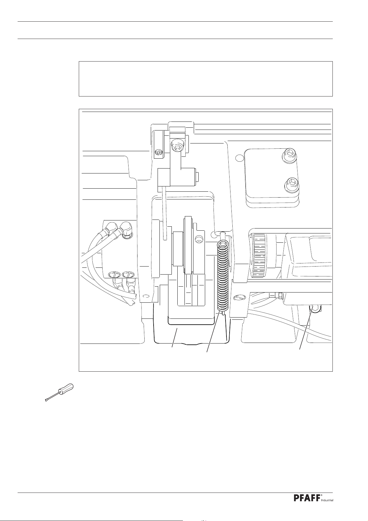
1.05.03 Zero position of the unison feed ........................................................................................... 7
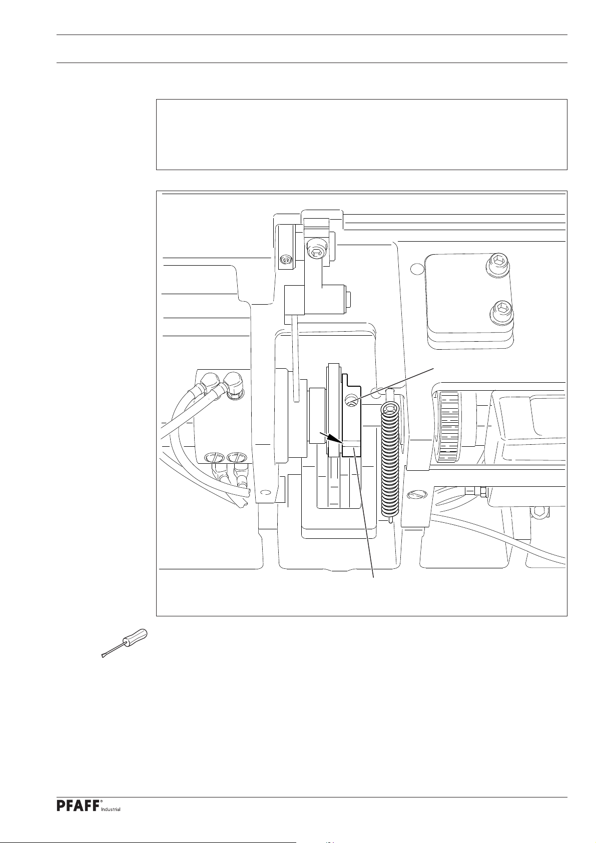
1.05.04 Feeding motion of the unison feed ....................................................................................... 8
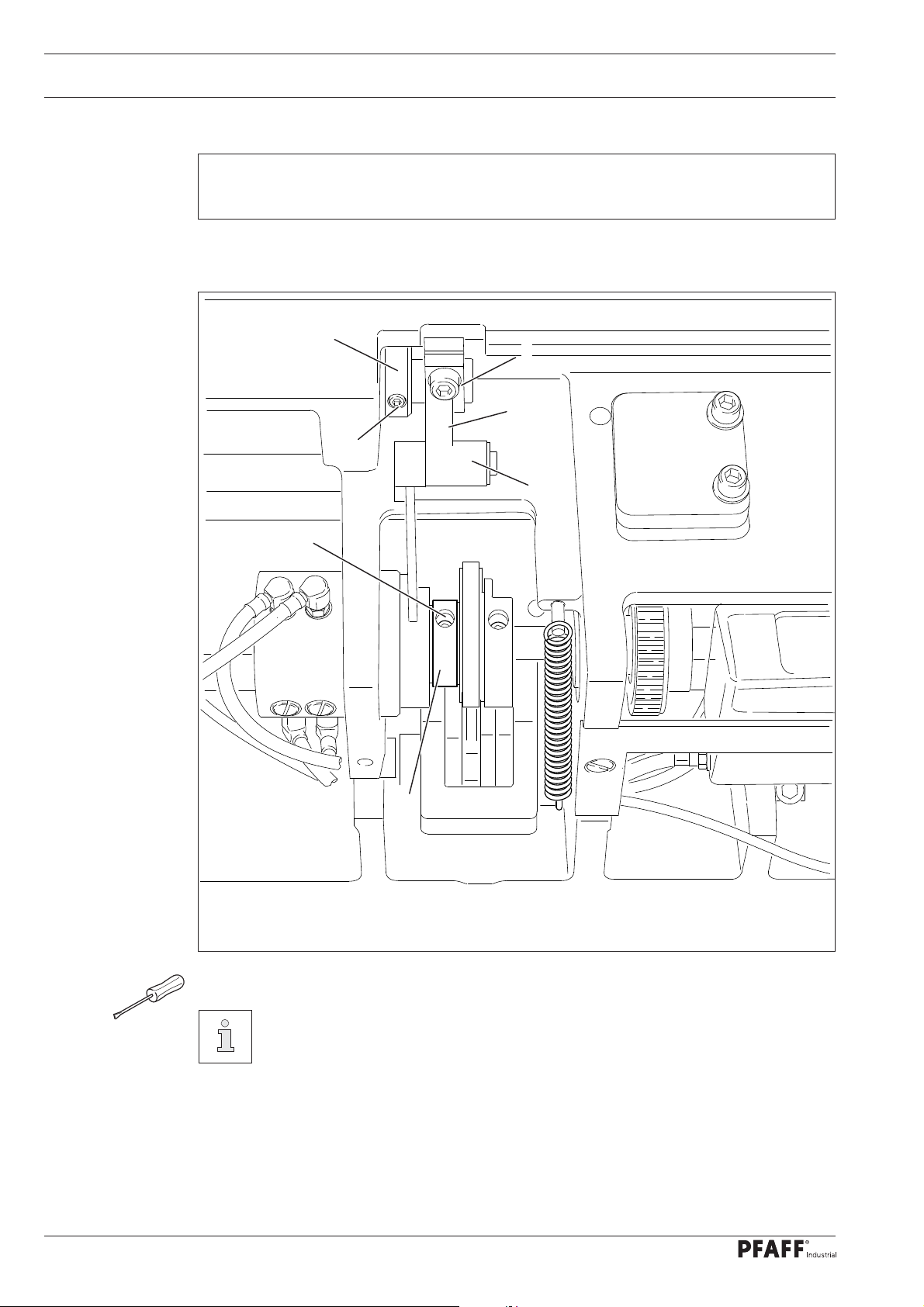
1.05.05 Lifting motion of the bottom feed dog ...................................................................................9
1.05.06 Height of the bottom feed dog ............................................................................................ 11
1.05.07 Feeding stroke difference .................................................................................................... 12
1.05.08 Preliminary adjustment of the needle height....................................................................... 13
1.05.09 Needle rise, hook clearance, needle height and needle guard ............................................ 14
1.05.10 Top feed stroke .................................................................................................................... 16
1.05.11 Top-feed lifting motion ......................................................................................................... 17
1.05.12 Adjusting the potentiometer for speed reduction................................................................ 18
1.05.12.01 On machines with drive P74 ED-L........................................................................................ 19
1.05.12.02 On machines with drive PF 321........................................................................................... 19
1.05.13 Bobbin case opener stroke ................................................................................................. 19
1.05.14 Adjusting the shortened trim stitch......................................................................................20
1.05.15 Bobbin winder...................................................................................................................... 21
1.05.16 Thread check spring and thread regulator............................................................................ 22
1.05.17 Sewing foot pressure........................................................................................................... 23
1.05.18 Lubrication ........................................................................................................................... 24
1.05.19 Limiting the stitch length ..................................................................................................... 25
1.05.20 Speed reduction................................................................................................................... 26
1.05.21 Re-engaging the slip-clutch.................................................................................................. 27
1.06 Adjusting the thread trimmer -900/81.................................................................................. 28
1.06.01 Resting position of roller lever/radial position of control cam .............................................. 28
1.06.02 Position and height of the thread catcher ............................................................................ 29
1.06.03 Knife pressure...................................................................................................................... 30
1.06.04 Bobbin thread clamp spring ................................................................................................. 31
1.06.05 Manual cutting test .............................................................................................................. 32

Index
Contents ................................................................................Page
1.07 Adjusting the thread trimmer device -900/82.................................................................. 35
1.07.01 Preliminary testing ............................................................................................................... 35
1.07.02 Assrémbly of the thread clamp carrier and thread catcher .................................................. 35
1.07.03 Check settings according to the following chapter: ............................................................ 35
1.07.04 Needle position in sewing direction.....................................................................................36
1.07.05 Bottom transporter in sewing direction ............................................................................... 37
1.07.06 Blade position ...................................................................................................................... 38
1.07.07 Thread catcher height .......................................................................................................... 39
1.07.08 Thread catcher position in sewing direction......................................................................... 40
1.07.09 Thread catcher position crossways to sewing direction ...................................................... 41
1.07.10 Position of the control curve ................................................................................................ 42
1.07.11 Thread clamp ....................................................................................................................... 43
1.07.12 Parameter values ................................................................................................................. 44
2Circuit diagrams................................................................................................................. 45

Adjustment
5
1 Adjustment
Please observe all notes from Chapter 1Safety of the instruction manual!
In particular care must be taken to see that all protective devices are refitted
properly after adjustment, see Chapter 1.06 Danger warnings of the instruc-
tion manual!
If not otherwise stated, the machine must be disconnected from the electrical
power supply. Danger of injury due to unintentional starting of the machine!
1.01 Notes on adjustment
All following adjustments are based on a fully assembled machine and may only be carried
out by expert staff trained for this purpose.
Machine covers, which have to be removed and replaced to carry out checks and adjust-
ments, are not mentioned in the text.
The order of the following chapters corresponds to the most logical work sequence for
machines which have to be completely adjusted. If only specific individual work steps are
carried out, both the preceding and following chapters must be observed.
Screws, nuts indicated in brackets ( ) are fastenings for machine parts, which must be
loosened before adjustment and tightened again afterwards.
1.02 Tools, gauges and other accessories for adjusting
●Screwdrivers with blade width from 2to 10 mm
●Spanners (wrenches) with jaw width from 7to 14 mm
●1set Allen keys from 1.5to 6mm
●1gauge for the top feed stroke 5.0mm (Part No. 61-111 633-60)
●1feed dog adjustment gauge, Part No. 61-111 689-04
●Metal rule (part No. 08-880 218-00)
●Sewing thread and test materials
1.03 Abbreviations
t.d.c. = top dead centre
b.d.c. = bottom dead centre
1.04 Explanation of the symbols
In this adjustment manual, symbols emphasize operations to be carried out or important in-
formation. The symbols used have the following meaning:
Note, information
Service, repair, adjustment, maintenance
(work to be carried out by qualified staff only)

Adjustment
6
1.05 Adjusting the basic machine
1.05.01 Basic position of the balance wheel (adjustment aid)
Requirement
When the needle bar is positioned at t.d.c., the marking "0" on the scale should be level
with the top edge of the belt guard (see arrow).
Fig. 1 - 01
1
2
2
127-01
●Adjust the scale dial 1( depending on model screws 2or 3) in accordance with the re-
quirement.
3
3

Adjustment
7
1.05.02 Balance weight
Requirement
When the needle bar is positioned at b.d.c. (balance wheel position 180°) the largest ec-
centricity of the balance weight 1should be at the top.
●Adjust balance weight 1(screw 2) in accordance with the requirement.
1
2
1
2
Fig. 1 - 02

Adjustment
8
1.05.03 Zero position of the unison feed
Requirement
When the stitch length is set at "0", the top and bottom feed dogs and the needle bar
should not make any feeding motion when the balance wheel is turned.
●Remove spring 1.
●Adjust crank 2(screw 3) in accordance with the requirement.
●Replace the spring 1.
Fig. 1 - 03
13
2

Adjustment
9
1.05.04 Feeding motion of the unison feed
Requirement
When the needle bar is positioned at b.d.c. (balance wheel position 180°), and the ma-
ximum stitch length is set, the top and bottom feed dogs and the needle bar should not
make any feeding motion when the reverse-feed lever is pressed.
●Adjust eccentric 1(screws 2) in accordance with the requirement. Make sure that the
cut-out (see arrow) is visible.
Fig. 1 - 04
1
2

Adjustment
10
1.05.05 Lifting motion of the bottom feed dog
Requirement
When the balance wheel is positioned at 180°, the feed dog should be at t.d.c.
●Adjust eccentric 1(screws 2) in accordance with the requirement.
Use the kit with the Order No. 91-501 399-90 to deactivate the transporter lif-
ting movement.
●Install assembly and adjust
●Remove collar 3(screws 4) and crank 5(screw 6, nut 7).
●Mount the preassembled parts of the kit as shown in figures 1 - 05a.
●Adjust bottom transporter height and stroke movement where required.
Fig. 1 - 05
1
2
3
4
6
5
7

Adjustment
11
Activate lifting movement
●Lifting movement is activated if connection part 8is swiveled in as shon in
figures 1- 05a, and screws 9(M6x 16) and 10 (M5x 16) have been attached.
Deactivate lifting movement
●Remove screws 9and 10 and swivel connection part 8(screw 11 ) towards the right.
●Replace screw 9with a screw M6x 25.
●Replace screw 10 with a threaded pin M5x 25 and tighten to stop.
Adjust transporter height with deactivated stroke movement so that the upper
edge of the transporte is at the height of the upper edge of the needle plate.
Adjust the transporter height once again with the stroke movement activated,
as described in chapter 1.05.06.
Fig. 1 - 05a
10
9
8
11
8

Adjustment
12
1.05.06 Height of the bottom feed dog
Requirement
1. When the needle bar is positioned at b.d.c. (balance wheel position 180°), the bottom feed
dog should be positioned 0.5mm horizontally above the top edge of the needle plate,
when crank 5is in the centre of the slot.
2. In the direction of sewing, the bottom feed dog should be positioned in the centre of
the needle plate slot.
●Turn lifting crank 1(screws 2) and eccentric sleeve 3(screws 4) according to Require-
ment 1, and set feed dog in centre of needle-plate slot as shown in Requirement 2.
The height of the bottom feed dog can also be increased or reduced as required
by moving crank 5(nut 6) up or down.
Fig. 1 - 06
0,5 mm
12
3
4
2
4
6
5

Adjustment
13
1.05.07 Feeding stroke difference
Requirement
With the maximum stitch length set, when the balance wheel is turned the feeding stro-
kes of the needle and the bottom feed dog should be the same.
●With connecting rod 1(nut 2) increase ("+") or reduce (-) the needle feed stroke in
accordance with the requirement.
12
Fig. 1 - 07

Adjustment
14
●Without turning it, re-position needle bar 1(screw 2) in accordance with the
requirement.
Make sure that needle bar 1and foot 3do not collide.
1
2
Fig. 1 - 08
22 mm
1
3
1.05.08 Preliminary adjustment of the needle height
Requirement
When the needle bar is positioned at t.d.c. (balance wheel position 0°), the clearance
between the needle point and the needle plate should be 22 mm.

Adjustment
15
1.05.09 Needle rise, hook clearance, needle height and needle guard
Requirement
With the stitch length set at "4.5" and in the needle rise position (see table)
1. The hook point 6should be positioned at "needle centre" with a hook-to-needle clea-
rance of 0.05 – 0.10 mm.
2. The top of the needle eye should be positioned 0.8mm below hook point 6. and
3. and needle guard 7must touch the needle just lightly.
●Loosen both screws of the gear drive of hook 1(under cover 2).
●Adjust hook 1and hook bearing 3(screws 4and 5) in accordance with requirement 1.
●Without turning it, re-position the needle bar in accordance with the requirement 2, also
see Chapter 1.05.08 Preliminary adjustment of the needle bar.
Needle rise position
Model C: Balance wheel position 204° / 2.0 mm
Model D: Balance wheel position 206° / 2.4 mm
Fig. 1 - 09
0,8 mm
6
5
5
4
2
3
7
8
1

Adjustment
16
●Adjust needle guard 7(screw 8) in accordance with requirement 3.
If the needle size is changed, a quick adjustment of hook bearing 3is possible,
after loosening screws 4and 5.

Adjustment
17
1.05.10 Top feed stroke
Requirement
With adjustment wheel 1set at "5", the top feed dog 7and presser foot 4should each
rise by 5.0mm.
●Remove the bottom feed dog and set adjustment wheel 1at "5".
●Loosen the screws of the needle plate, place the metal gauge over the opening of the
needle plate slot so that both sewing feet can be lowered onto the metal gauge.
●For the preliminary adjustment, adjust crank 2(screw 3) so that there is a clearance of 5
mm between presser foot 4and the needle plate.
●Adjust crank 5(screw 6) so that top feed dog 7and presser foot 4have the same stroke.
●Check the adjustment in accordance with the requirement, and correct if necessary.
Fig. 1 - 10
7
5 mm
4
5 mm
23
56
1

Adjustment
18
2 mm
1
2
Fig. 1 - 11
1.05.11 Top-feed lifting motion
Requirement
The top feed dog should just have reached the needle plate when the presser foot lift is
set at 5mm and the needle descending from above is 2mm above the needle plate.
●Turn eccentric 1(screw 2) in accordance with the requirement.

Adjustment
19
1.05.12 Adjusting the potentiometer for speed reduction
1.05.12 .01 Machines with P74 ED-L
●Switch on the machine
●Set the smallest stroke "0".
●Using the stroke adjustment function, call up the smallest stroke (LED off), see the Cont-
rol Panel Instruction Manual.
●Call up parameter "501" and press key "C+" to save the bottom value.
●Set the inner adjustment wheel at maximum stroke "9".
●Using the stroke adjustment function, call up the largest stroke (LED on), see the Control
Panel Instruction Manual.
●Call up parameter "502" and press key "C+" to save the top value.
The speed is adjusted in accordance with Chapter 3.03 Maximum Speed in
the Instruction Manual.
1.05.12.02 Machines with PF 321
●Press "P" on the control panel, while simultaneously switching the machine on.
●Enter the code 3112 via the numbered keys and confirm by pressing "E".
●Select parameter 501 via the numbered keys and confirm by pressing "E".
●Set the smallest stroke "0".
●Using the stroke adjustment function, call up the small stroke (LED off), see instruction
manual.
●Take over the value displayed under parameter 501 by pressing "+".
●Select parameter 502 via the numbered keys.
●Set the largest stroke "0".
●Using the stroke adjustment function, call up the large stroke (LED on).
●Take over the value displayed under parameter 502 by pressing "+".
●Press "P" twice to quit the input level
●The new values are taken over when sewing is started, and these are maintained
evenafter the machine is switched off.
The speed is adjusted in accordance with Chapter 3.03 Maximum Speed
in the instruction manual.
Under parameter 117 the speed at max. stroke adjustment can be reduced
again.

Adjustment
20
1.05.13 Bobbin case opener stroke
Requirement
When the balance wheel is turned
1. The beak 4, when it is at the right point of reversal of the bobbin case opener 1,
should rise from the needle plate 5by the thickness of the thread.
2. The bobbin case opener 1should be at its left point of reversal when the balance
wheel is positioned at "10°".
●Adjust bobbin case opener 1(screw under cover 2) in accordance with requirement 1.
●Adjust the eccentric (screw under cover 3) in accordance with requirement 2.
The thread must be able to pass unhindered between bobbin case opener 1
and bobbin case 6.
Fig. 1 - 13
4
5
1
6
3
2
Other manuals for Powerline 2545
2
This manual suits for next models
1
Table of contents
Other Pfaff Sewing Machine manuals

Pfaff
Pfaff tipmatic tiptronic 1151 User manual

Pfaff
Pfaff Synchromatic 1215 User manual

Pfaff
Pfaff dorina 72 User manual

Pfaff
Pfaff CREATIVE 4.0 - User manual

Pfaff
Pfaff PowerLine 2235 User manual

Pfaff
Pfaff hobbylock 4762 User manual

Pfaff
Pfaff 145 User manual

Pfaff
Pfaff 335 User manual

Pfaff
Pfaff 918 User manual

Pfaff
Pfaff passport 2.0 User manual