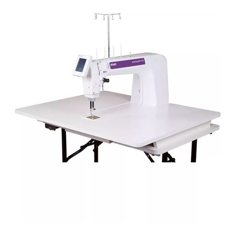
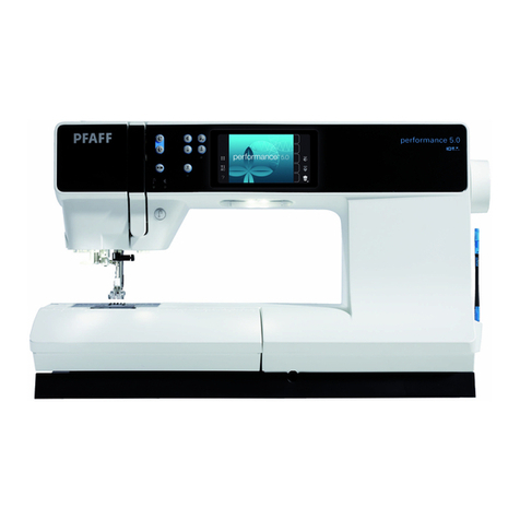
Pfaff POWERline 2591 ME User manual

This service manual applies to machines
from software version 0389/001 and serial
number 2 766 760 onwards
296-12-19 129/002
Justieranleitung engl. 09.10
SERVICE MANUAL
2591 ME
2591 PREMIUM

The reprinting, copying or translation of PFAFF Service Manuals, whether in whole or
in part, is only permitted with our previous authorization and with written reference
to the source.
PFAFF Industriesysteme
und Maschinen AG
Hans-Geiger-Str. 12 - IG Nord
D-67661 Kaiserslautern

Index
Contents ................................................................................ Page
1Adjustment ........................................................................................................................... 5
1.01 Notes on adjustment ............................................................................................................. 5
1.02 Tools, gauges and other accessories for adjusting ............................................................... 5
1.03 Abbreviations ......................................................................................................................... 5
1.04 Explanation of the symbols.................................................................................................... 5
1.05 Adjusting the basic machine .................................................................................................. 6
1.05.01 Basic position of the balance wheel (adjustment aid)............................................................ 6
1.05.02 Balance weight ...................................................................................................................... 7
1.05.03 Needle position in the direction of sewing ............................................................................ 8
1.05.04 Limiting the needle bar frame.............................................................................................. 10
1.05.05 Preliminary adjustment of the needle height....................................................................... 11
1.05.06 Needle rise, Gripper distance, Needle height and Needle guard......................................... 12
1.05.07 Needle position crosswise to sewing direction ................................................................... 14
1.05.08 Height and stroke of the bobbin case opener...................................................................... 15
1.05.09 Height of the feed wheel ..................................................................................................... 16
1.05.10 Roller-presser ....................................................................................................................... 17
1.05.11 Clearance between roller presser and feed wheel .............................................................. 18
1.05.12 Knee lever ............................................................................................................................ 19
1.05.13 Tension release .................................................................................................................... 20
1.05.14 Thread check spring and thread regulator ............................................................................ 21
1.05.15 Bobbin winder...................................................................................................................... 22
1.05.16 Sewing foot pressure........................................................................................................... 23
1.05.18 Lubrication ........................................................................................................................... 24
1.05.19 Re-engaging the slip-clutch .................................................................................................. 25
1.06 Adjusting the thread trimmer -900/81.................................................................................. 26
1.06.01 Resting position of the roller lever / radial position of the control cam................................ 26
1.06.02 Position of the thread catcher holder ...................................................................................27
1.06.03 Distance between thread catcher and needle plate ............................................................ 28
1.06.04 Position of the thread catcher .............................................................................................. 29
1.06.05 Knife position and knife pressure......................................................................................... 30
1.06.06 Bobbin thread retaining spring............................................................................................. 31
1.06.07 Manual cutting test .............................................................................................................. 32
Index
Contents ................................................................................Page
1.07 List of parameters for control P321 ..................................................................................... 33
1.08 Error Messages and Description.......................................................................................... 38
1.09 Motor Errors......................................................................................................................... 39
1.10 Internet-Update der Maschinen-Software............................................................................ 40
1.10.01 Updating 2591 ME (with null modem cable) ...................................................................... 40
1.10.02 Updating 2591 PREMIUM (with SD card) ........... ............................................................... 41
2 Circuit diagrams................................................................................................................. 43

Adjustment
5
1 Adjustment
Please observe all notes from Chapter 1Safety of the instruction manual!
In particular care must be taken to see that all protective devices are refitted
properly after adjustment, see Chapter 1.06 Danger warnings of the instruc-
tion manual!
If not otherwise stated, the machine must be disconnected from the electrical
power supply. Danger of injury due to unintentional starting of the machine!
1.01 Notes on adjustment
All following adjustments are based on a fully assembled machine and may only be carried
out by expert staff trained for this purpose.
Machine covers, which have to be removed and replaced to carry out checks and adjust-
ments, are not mentioned in the text.
The order of the following chapters corresponds to the most logical work sequence for
machines which have to be completely adjusted. If only specific individual work steps are
carried out, both the preceding and following chapters must be observed.
Screws, nuts indicated in brackets ( ) are fastenings for machine parts, which must be
loosened before adjustment and tightened again afterwards.
1.02 Tools, gauges and other accessories for adjusting
Screwdrivers with blade width from●2to 10 mm
Spanners (wrenches) with jaw width from●7to 14 mm
1●set Allen keys from 1.5to 6mm
Setting gauge (Needle position in sewing direction Order No.●61-111 641-48)
Step gauge●
Metal rule (part No.●08-880 218-00)
Sewing thread and test materials●
1.03 Abbreviations
t.d.c. = top dead centre
b.d.c. = bottom dead centre
1.04 Explanation of the symbols
In this adjustment manual, symbols emphasize operations to be carried out or important in-
formation. The symbols used have the following meaning:
Note, information
Service, repair, adjustment, maintenance
(work to be carried out by qualified staff only)

Adjustment
6
Fig. 1 - 01
1
2
2
127-01
1.05 Adjusting the basic machine
1.05.01 Basic position of the balance wheel (adjustment aid)
Requirement
When the needle bar is positioned at t.d.c., the marking "0" on the scale should be level
with the top edge of the belt guard (see arrow).
Adjust the scale dial 1(four screws 2) in accordance with the requirement.

Adjustment
7
Fig. 1 - 02
1
2
1
2
1.05.02 Balance weight
Requirement
When the needle bar is positioned at b.d.c. (balance wheel position 180°) the largest ec-
centricity of the balance weight 1should be at the top.
Adjust balance weight●1(screw 2) in accordance with the requirement.

Adjustment
8
1.05.03 Needle position in the direction of sewing
Requirement
With the stitch length set at "5", in its front and rear point of reversal the needle should be
the same distance from the inside edges of the needle hole.
Turn on machine and set stitch length to "●5".
Turn machine off and on (synchronise needle bar to stitch length).●
Sew a stitch and check the rear position of the needle according to the requirement.●
Press the stitch control key, sew a stitch and check the forward position of the needle ac-●
cording to the requirement and where necessary make the following adjustments.
Turn off machine and loosen screws●1and 2.
Push the adjusting pin's angled part (Order No.●61-111Snnb641-48 through hole 3
into the hole in lever 4.
Fig. 1 - 03
3
4
2
5
=
=
1

Adjustment
9
Move the needle bar frame●5according to the requirement and tighten screw 1.
Check according to the requirement.●
Screws●2remain loosened for the subsequent adjustment.

Adjustment
10
Fig. 1 - 04
1.05.04 Limiting the needle bar frame
Requirement
With the stitch length set at "5", when the needle is in its front and rear point of reversal
screw 3should be the same distance from the inside edge of its hole..
Set stitch length to "●5".
Select parameter●605.
Turn the handwheel in the direction of rotation and check the "requirement".●
If necessary move regulating bow●1(screw 2).
3
2
1
3
=
=

Adjustment
11
Fig. 1 - 05
1.05.05 Preliminary adjustment of the needle height
Requirement
When the needle bar is positioned at t.d.c. (handwheel position 0°) there should be a gap
between upper edge needle bar and upper edge needle pendulum of about 54 mm.
Without turning it, re-position needle bar●1(screw 2) in accordance with the
requirement..
2
1
54 mm

Adjustment
12
Fig. 1 - 06
1.05.06 Needle rise, Gripper distance, Needle height and Needle guard
Requirement
With the needle bar positioned 2.0 mm after BDC (balance wheel position 202°) and the
stitch length set at "0.8"
the hook point must be at needle centre with a hook-to-needle clearance of1. 0.05 to 0.1 mm;
the top of the needle eye must be2. 0.8to 1.0 mm below the hook point;
the needle guard3. 6must touch the needle lightly.
Set stitch length at "●0.8".
Loosen screws●1, 2, 3, and 4as well as screw 5on both sides of the post.
Select parameter●605.
Unscrew the needle plate.●
Turn the handwheel four times in the direction of rotation.●
Bring the handwheel into position●202° (= needle bar position 2.0mm after b.d.c.)
Set the hook point on the middle of the needle. Take care that the needle is not●
squeezed by needle guard 6.
Adjust the needle height according to requirement●2, cf. chapter 1.05.05 Preliminary Ad-
justment of Needle Height.
Move hook post according to requirement●1and tighten screws 4.
4
5
86-009
61-028
123
4
6
7
8
9
0,8 - 1 mm

Adjustment
13
Tighten screws●2allowing for bevel gear wheel movement.
Move collar●7up against bevel gear wheel 8and tighten screws 1.
Screws●5remain loosened for further adjustments.
Adjust needle guard●6(screw 9) according to requirement 3.
When changing a clamp take care that the
markings 10 and 11 are on one side.
10
11

Adjustment
14
Fig. 1 - 07
1.05.07 Needle position crosswise to sewing direction
Requirement
As seen crosswise to the sewing direction, the needle must penetrate in the centre of
the needle hole.
Adjust feed wheel post●1(screws 2, 3and 4) according to the requirement.
1
2
63-019
4
4
4
4
3

Adjustment
15
Fig. 1 - 08
1.05.08 Height and stroke of the bobbin case opener
Requirement
The top edges of the bobbin case opener1. 1and bobbin case base 3should be on one
level.
When the bobbin case opener2. 1has deflected the bobbin case to its furthest point,
the catch of the bobbin case should be 0.3- 0.5mm from the back edge of the needle
plate recess.
Adjust bobbin case opener●1(screw 2) in accordance with requirement 1.
Turn the balance wheel until the bobbin case opener has deflected the bobbin case●
to its furthest point.
Adjust bobbin case opener●1(screw 2) in accordance with requirement 2.
0,3 - 0,5 mm
3
1
1
2

Adjustment
16
Fig. 1 - 09
1.05.09 Height of the feed wheel
Requirement
The feed wheel should protrude from the needle plate by tooth height (approx. 0.8mm)
Swing out the roller presser.●
Loosen screws●1.
Adjust eccentric●3(fastening screw accessible through hole 2) according to the
requirement.
3
2
1
61-039
0,8 mm

Adjustment
17
Fig. 1 - 10
1.05.10 Roller-presser
Requirement
When the roller-presser 1is resting on the feed wheel 6it must
be parallel to the feed wheel1. 6when viewed in the direction of sewing,
be in the middle of the (needle when viewed in the direction of sewing and2.
be as close as possible to the needle when viewed in transverse direction of sewing.3.
Raise the roller-presser●1.
Place roller-presser bracket●2(screws 3) flush to the bottom edge of presser bar 4.
Always observe●requirement 1when carrying out the following adjustments.
Move the roller-presser●1( screw 5) in accordance with requirement 2.
Allow the roller-presser●1to come to rest on the feed wheel 6.
Move bracket●7(screw 8) according to requirement 3.
When sewing very tight curves the roller-presser 1should be moved toward
the operator slightly.
57
8
6
1
42
3

Adjustment
18
Fig. 1 - 11
1.05.11 Clearance between roller presser and feed wheel
Requirement
With a resting roller-presser there should be a gap between the lift piece1. 1and the
housing of about 3mm.
With a raised roller-presser the distance between roller-presser and feed wheel should2.
be 8mm.
Set the roller-presser down on the needle plate.●
Decrease roller-presser pressure.●
Adjust lift piece●1(screws 2) according to the requirement 1.
Push magnet bracket●3(screws 4) downwards as far as it will go.
Raise the roller-presser and place an●8mm gauge under the roller-presser.
With magnet plunger●5extended, move lever 6up against lift piece 1a and mount lever 7
(screws 8) on to magnet plunger 5.
Check according to the requirement.●
3 mm
1
2
61-040
8 mm
5
7
8
4
3
61a

Adjustment
19
Fig. 1 - 12
1.05.12 Knee lever
Requirement
When the knee lever is pressed the roller-presser should raise up1. 7mm
Before the roller-presser raises up, the knee lever should have a little bit of clearance.2.
Turn screw●1(nut 2) according to requirement 1 .
Turn screw●3(nut 4) according to requirement 2.
4
1
23
61-040
7 mm

Adjustment
20
Fig. 1 - 13
1.05.13 Tension release
Requirement
With the roller-presser raised the tension shims 3should be about 0.5mm loosened from
each other.
Raise roller-presser and calibrate lever●1(screw 2) according to the requirement.
1
2
0,5 mm
3
This manual suits for next models
1
Table of contents
Other Pfaff Sewing Machine manuals

Pfaff
Pfaff Creative Vision User manual

Pfaff
Pfaff 1571 User manual

Pfaff
Pfaff 3119 User manual

Pfaff
Pfaff 3819 series User manual

Pfaff
Pfaff Powerline 2545 User manual

Pfaff
Pfaff 2438 plusline User manual

Pfaff
Pfaff Hobbylock 4860 User manual

Pfaff
Pfaff 1571 User manual

Pfaff
Pfaff Creative 1467A User manual

Pfaff
Pfaff select 8.0 User manual

Pfaff
Pfaff 284 User manual

Pfaff
Pfaff 3511-3/01 User manual

Pfaff
Pfaff 561 User manual

Pfaff
Pfaff hobby 307 User manual

Pfaff
Pfaff CREATIVE 2124 User manual

Pfaff
Pfaff 3516-1/25 User manual

Pfaff
Pfaff Tiptronic 1071 User manual

Pfaff
Pfaff 481 User manual

Pfaff
Pfaff 3582-2/01 User manual

Pfaff
Pfaff 3834-14/11 User manual