Pfaff Series 580 Owner's manual

296-12-18 988/002
Betriebsanleitung engl. 03.11
-948/26
Supplement to the instruction manual for
the series 580, 1180, 3701, 5480
This instruction manual applies to machines
from software version P350 EDX # 1_052_13
onwards

The reprinting, copying or translation of PFAFF Instruction Manuals, whether in whole or
in part, is only permitted with our previous authorization and with written reference to the
source.
PFAFF Industriesysteme
und Maschinen AG
Hans-Geiger-Str. 12 - IG Nord
D-67661 Kaiserslautern

Index
Contents ..................................................................................Page
1Proper use............................................................................................................................. 4
1.01 Using standard presser feet .................................................................................................. 4
2Controls ................................................................................................................................ 5
2.01 Puller functions ...................................................................................................................... 5
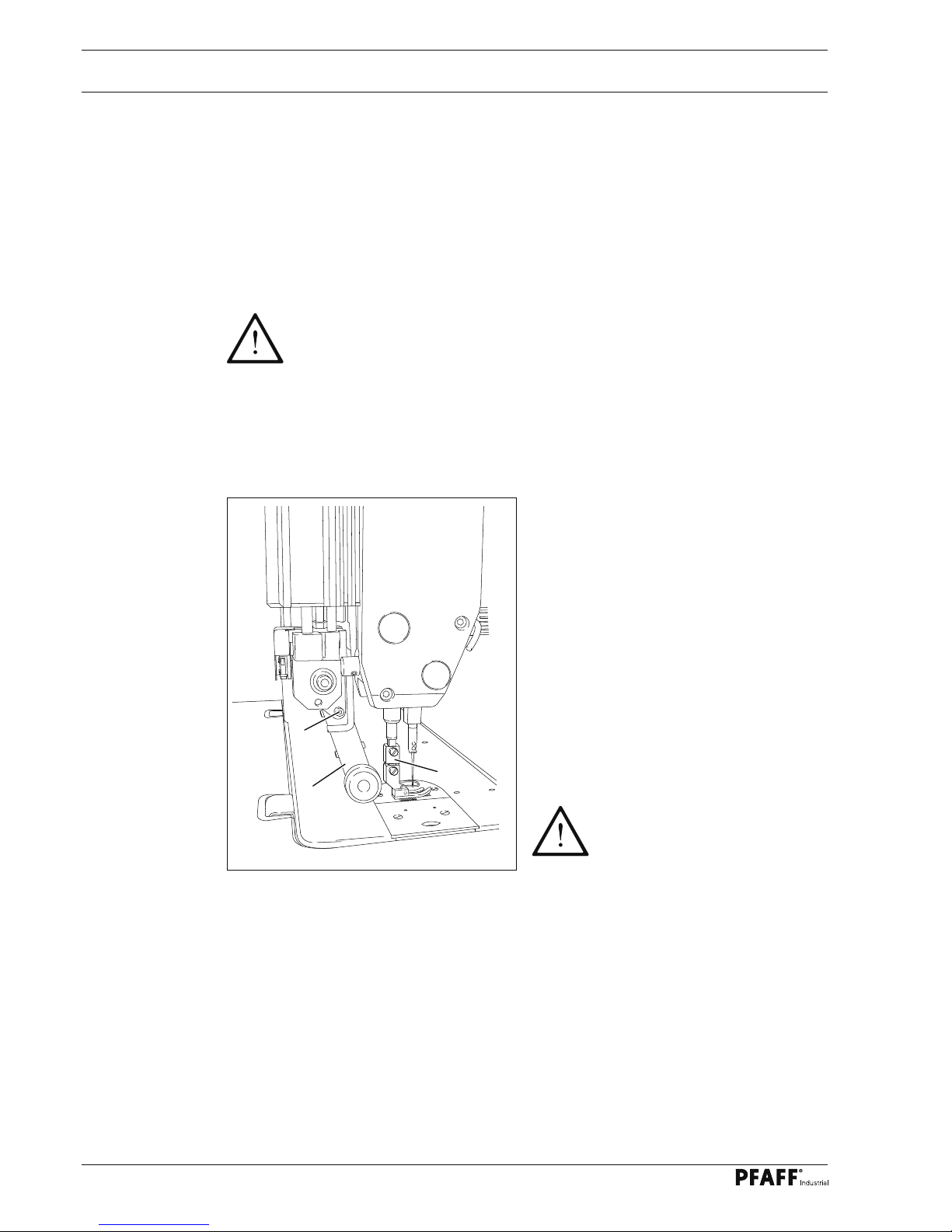
2.02 Aligning the puller .................................................................................................................. 5
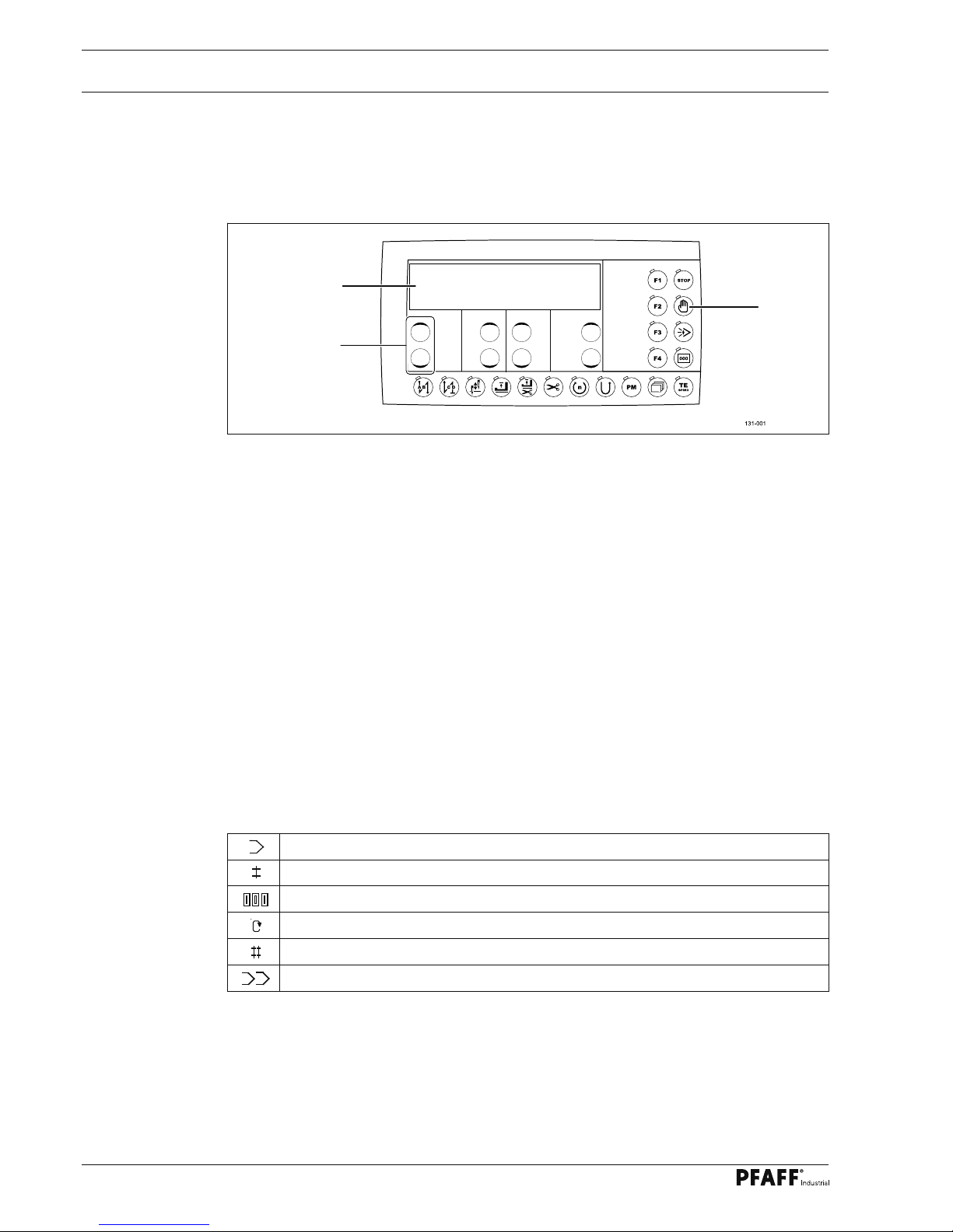
2.03 Control panel.......................................................................................................................... 6
2.03.01 Symbols on the display .......................................................................................................... 6
2.03.02 Plus-minus keys ..................................................................................................................... 7
2.03.03 Function keys ......................................................................................................................... 7
3Commissioning .................................................................................................................... 9
3.01 Basic position of the machine drive ....................................................................................... 9
4Setting up ........................................................................................................................... 10
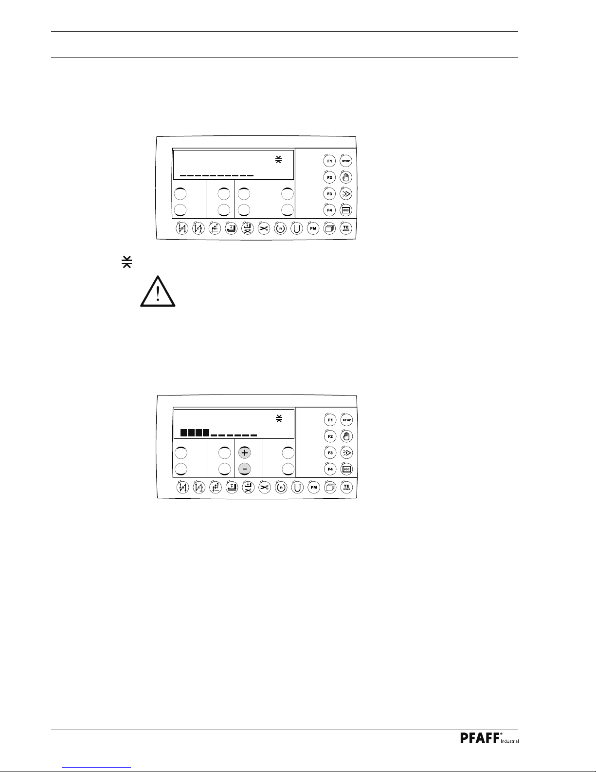
4.01 Entering the puller feed stroke (stitch length) ...................................................................... 10
4.02 Setting the puller pressure................................................................................................... 10
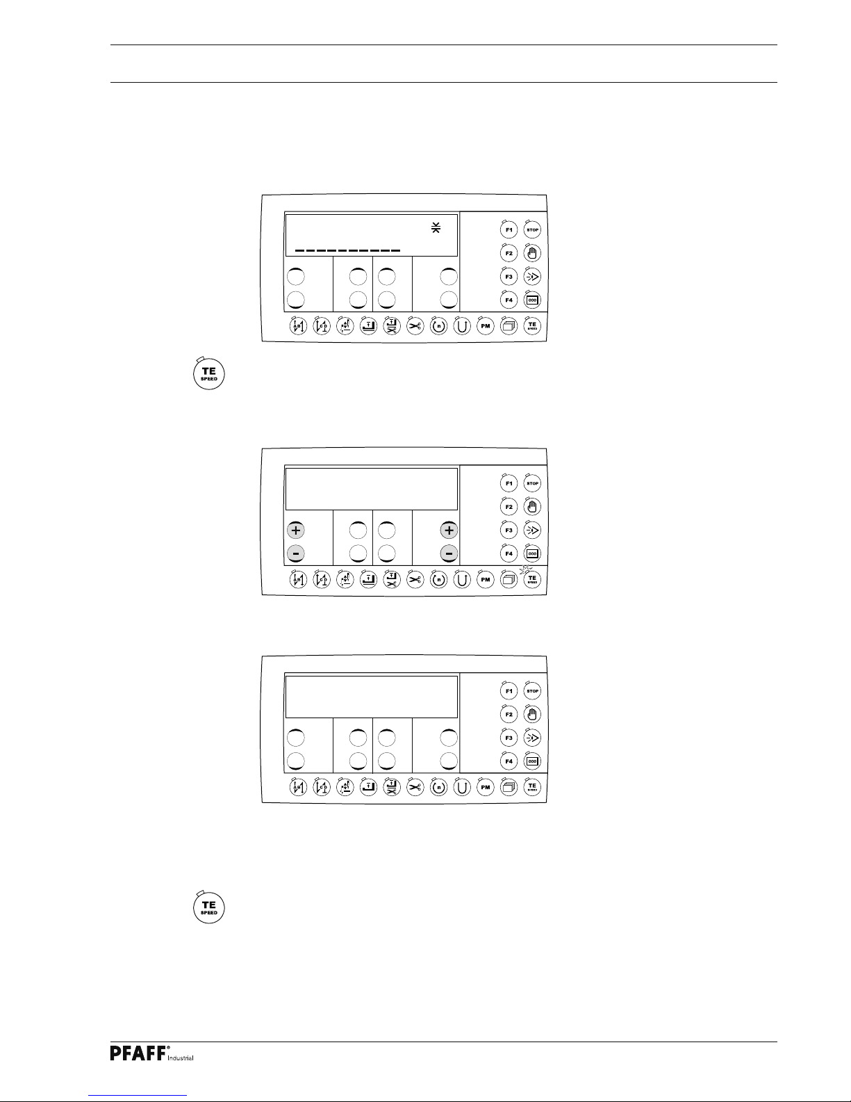
4.03 Entering the maximum speed ............................................................................................. 11
4.04 Entering the start and end backtacks................................................................................... 11
4.05 Setting the stitch counting function for the bobbin thread control....................................... 12
5Sewing ................................................................................................................................ 13
5.01 Manual sewing..................................................................................................................... 13
5.02 Programmed sewing............................................................................................................ 14
5.03 Error messages.................................................................................................................... 15
5.03.01 Description of the error messages ...................................................................................... 15
6Parameter input.................................................................................................................. 16
6.01.01 Example of how to enter the parameters............................................................................ 16
6.01.02 Selecting the user level........................................................................................................ 17
6.02 Parameter list....................................................................................................................... 18
7Service functions................................................................................................................ 27
7.01 Reset / Cold start ................................................................................................................. 27
7.02 Hardware-test ...................................................................................................................... 28
7.02.01 Test block 1 – inputs ............................................................................................................ 28
7.02.02 Test block 2 – outputs .......................................................................................................... 29
7.02.03 Test block 3 – speed control unit ......................................................................................... 29
7.02.04 Test block 4 – actual value transmitter .................................................................................30
7.02.05 Test block 5 – light barrier .................................................................................................... 30
7.02.06 Test block 6 – thread monitor (only on subclass -926/06) .................................................... 31
7.02.07 Test block 7. - puller ........................................................................................................... 31
7.02.08 Test block 8 – data transfer ............................................................................................... 32
8Circuit diagrams................................................................................................................. 33

Proper use
4
1.01 Using standard presser feet
●With the adapter 1which belongs to
the accessories, standard presser feed
can also be used(Ordering number
91-154 790-22).
●Mount adapter 1as shown in Fig. 1-01.
●Loosen screw 2 and push puller arm 3
back.
●Screw the presser foot onto adapter 1.
●Adjust puller arm 3 so that there is a
clearance of approx. 1 mm between the
puller roller and the presser foot.
●Tighten screw 2.
When using the adapter, the
height of the puller roller must
be adjusted as described in
Chapter 2.02.
Fig. 1 - 01
1 Proper use
With the puller the workpiece is fed continously, which makes it possible to sew to a great
extent without shifting and puckering. The puller’s linear motor enables an individual clearan-
ce space between the needle plate and the puller roller.
All adjustments, such as e.g. puller feed stroke, puller roller clearance etc. are carried out by
altering the parameter values, see Chapter 2.03.03 Selecting and altering parameters.
Any use of these machines which is not approved by the manufacturer shall be
considered as improper use! The manufacturer shall not be liable for any dam-
age arising out of improper use! Proper use shall also be considered to include
compliance with the operation, adjustment, service and repair measures speci-
fied by the manufacturer!
1
2
3

5
Controls
Fig. 2 - 01
Engaging/disengaging the puller
●Raise the puller drive unit 1until it locks
into place and swing puller arm 2back as
far as possible. To engage the puller, fol-
low the instructions in the reverse order.
Switching the puller on/off
●The puller is automatically switched on
or off when the puller unit is engaged or
disengaged.
Setting the puller feed motion
●The feed motion of the puller is set
by means of parameters (see Chap.
6 Parameter settings)
Fig. 2 - 02
2.02 Aligning the puller
Puller crosswise to sewing direction
●Loosen screw 1.
●Align puller 2to the seam.
●Tighten screw 1.
Height of the puller roller
●Loosen screw 3
●Align puller 2, so that there is a clearan-
ce of approx. 0.3 mm between the puller
roller 4and the cloth plate.
●Tighten screw 3.
2 Controls
2.01 Puller functions
1
1
3
2
4
2

6
Controls
Fig. 6 - 02
1
3
2
2.03.01 Symbols on the display
In addition to texts and set values, the following symbols are shown on the display. The sym-
bols only appear in the programmed sewing mode, see Chapter 5.02 Programmed Sewing.
Current program number
Current seam sector
Number of stitches in current seam sector
Maximum speed in current seam sector
Number of seam sectors in current seam program
Program number of the seam program to be linked
2.03 Control panel
The control panel is used to display and call up the machine functions for setting up and for
sewing operation, for entering parameter values and for reading error messages and service
settings.
The control panel has the following control and display elements:
●The display screen 1consists of a two-line, alphanumerical LCD display with 16 symbols
per line and is used to show relevant information and selection parameters.
●The plus-minus keys 2are used to select or alter the functions and parameters shown on
the display.
●The function keys 3are used to switch the relevant function on or off. Activated functions
are shown in each case by an illuminated LED.

7
Controls
2.03.02 Plus-minus keys
The relevant plus-minus keys are used for the selection and alteration of the set values con-
cerned (e.g. when entering bartack stitches). In this case the relevant plus or minus key
is pressed and held while the set value shown above the key slowly changes. If the key is
pressed longer, the set value changes more quickly.
2.03.03 Function keys
The activated function is always shown by the relevant illuminated LED.
Description of the individual functions:
Start bartack
If this key is pressed, the securing stitches at the beginning of the seam (start bartacks) are
switched on or off. The number of forward stitches (A) or reverse stitches (B) for the start
bartack can be changed in each case by pressing the +/- key underneath. To change from
double tacks to single tacks set the forward stitches (A) at zero.
End bartack
●If this key is pressed, the securing stitches at the end of the seam (end bartacks) are
switched on or off. The number of reverse stitches (C) or forward stitches (D) can be
changed in each case by pressing the +/- key underneath. To change from double tacks to
single tacks set the forward stitches (D) at zero.
Raised needle position after sewing stop
●If this key is pressed, the "raised needle position after sewing stop" function is switched
on or off. If the function is switched on, the needle positions in t.d.c. after sewing stops
Raised foot position after sewing stop
●If this key is pressed, the "raised foot position after sewing stop" function is switched on
or off. If the function is switched on, the sewing foot is raised after sewing stops.
Foot position up at end of seam section (with programmed sewing)
●The "Foot position up at end of seam section" function is turned on or off by pressing this
button. If the function is switched on, the sewing foot is raised at the end of the seam
sector.
Thread trimming
●If this key is pressed, the "thread trimming" function is switched on or off
A B C D
3 3 3 3

8
Controls
Program speed (only in programmed sewing)
●If this key is pressed, the relevant function is switched on or off.
If the function is activated, the pedal forwards function is used to select the program
speed as a fixed speed. The pedal setting for stopping the fixed speed is chosen with
parameter 206.
●If the function is switched off, the speed is regulated with the pedal until program speed
is reached.
Reverse sewing direction (only in programmed sewing)
●If this key is pressed, the relevant function is switched on or off. If the function is activa-
ted during programmed sewing, the relevant seam sector is sewn in reverse
Manual sewing sector (only in programmed sewing)
●If this key is pressed, the relevant function is switched on or off.
If the function is activated, switching to the next seam sector is not carried out by stitch
counting or sensor, but manually with the pedal setting "-2".
Programmed sewing stop (only in programmed sewing)
●If this key is pressed, the relevant function is switched on or off.
If the function is activated, the machine stops at the end of the seam sector.
Sewing with light barrier
●In the manual sewing mode with light barrier, the number of stitches entered with pa-
rameter 111 corresponds to the light barrier compensation stitches. In the programmed
sewing mode, the number of stitches in the seam sector is used as the number of com-
pensation stitches.
Stitch counting (only in programmed sewing)
●If this key is pressed, the relevant function is switched on or off.
●If the function is activated, in the programmed sewing mode the machine switches to
the next seam sector after the number of stitches entered have been sewn.
TE/Speed
●In the programmed sewing mode, the number of stitches is entered by stitching them
off.
●If this key is pressed once, the machine changes to parameter input.
●If this key is pressed twice (within 5seconds) the machine changes to stitch input.
Scroll
●Press this key to scroll through the sub-menus of the program.
PM / Operating mode
●If this key is pressed, the machine switches between manual and programmed sewing. If
the LED is illuminated, programmed sewing is active.
F1 - F4
No function at present.

9
Commissioning
3 Commissioning
3.01 Basic position of the machine drive
●Switch on the machine.
●Press the TE/Speed key twice to call up the parameter input function (LED on).
●Select the technician level B(value "1") with parameter "798", see Chapter 6 parameter
input.
2x
No VAL
B 798 1
●By pressing the corresponding +/- key select the parameter group "700".
No
B 700 0
●Sew a stitch by operating the pedal.
●Turn the balance wheel in the direction of sewing until the needle point is level with the
top edge of the needle plate.
●Press the TE/Speed key to take over the setting and to conclude the input.
4000 PUL 30%
2.0mm

Setting up
10
4 Setting up
4.01 Entering the puller feed stroke (stitch length)
●Switch on the machine.
●Enter the feed stroke by pressing the corresponding +/- key.
The puller feed stroke setting must match the stitch length setting of the basic
machine!
●Switch on the machine.
●Set the desired puller pressure by pressing the corresponding +/- key.
The value for the current puller pressure (in %) can be read on the display.
4.02 Setting the puller pressure
4000 PUL 30%
2.0mm
4000 PUL 30%
2.0mm

Setting up
11
4.03 Entering the maximum speed
●Switch on the machine.
●Enter the maximum speed by pressing the corresponding +/- key.
The max. speed is limited with parameter 607.
4.04 Entering the start and end backtacks
●Switch on the machine.
●Press the TE/Speed key twice to select the input menu for start and end backtacks.
A B C D
3 3 3 3
●By pressing the corresponding +/- key select the desired value for the number of forward
stitches (A) of the start backtack.
●By pressing the corresponding +/- key select the desired value for the number of reverse
stitches (B) of the start backtack.
●By pressing the corresponding +/- key select the desired value for the number of reverse
stitches (C) of the end backtack.
●By pressing the corresponding +/- key select the desired value for the number of forward
stitches (D) of the end backtack.
In the programmed sewing mode it is possible to call up the input menu for
start and end backtacks by pressing the scroll key, see Chapter 5.02 Program-
med sewing.
2x
4000 PUL 30%
2.0mm

Setting up
12
4.05 Setting the stitch counting function for the bobbin thread control
●Switch on the machine.
●Press the TE/Speed key twice to call up the parameter input function (LED on).
●By pressing the corresponding +/- key select the parameter "760".
No VAL
A 101 ON
2x
●Press the corresponding +/- key to set the number of remaining stitches, which
can still be sewn after recognition by the bobbin thread control function.
The selected value is multiplied by 10* or 200** and the result is the number of stitches.
●Example display 5x 200** = 1000 stitches. The setting depends among other things on
the thread strength.
●If the TE/Speed key is pressed, the value is taken over and the machine changes into the
sewing mode.
The bobbin thread rest counter can only be used, if parameter "660" is set at
value "1" or "2".
*If for parameter 660 the value is "1", the multiplier is 10
** If for parameter 660 the value is "2", the multiplier is 200
No VAL
A 760 5

Sewing
13
5 Sewing
In the sewing mode all relevant adjustments for the sewing operation are shown on the
display and can be altered directly. Functions can be switched on and off by pressing the key.
The "PM" function key is used to choose between manual sewing (LED off) and program-
med sewing (LED on).
5.01 Manual sewing
After the machine has been switched on, the maximum speed, the puller feed stroke and
the puller pressure can be adjusted with the corresponding +/- keys.
Further functions in manual sewing, also see Chapter 2.03.03 Function keys:
Start backtacks on/off Presser foot raised at end of seam
on/off
End backtacks on/off Thread trimming on/off
Needle position raised
on/off Sensor on/off
Presser foot raised on/off
On the basic machine the stitch length is adjusted with the balance wheel.
The stitch length for the puller is adjusted on the control panel
4000 PUL 30%
2.0mm

Sewing
14
5.02 Programmed sewing
In the programmed sewing mode 99 programs, each with 9seam sections and 999 stitches,
can be programmed.
The fixed programs are used for the quick and easy production of seams with different
numbers of stitches. The pedal setting "0" is used to switch to the next seam section.
After the machine has been switched on and the programmed sewing mode has been
selected with the PM key, the display appears for selecting the program number, seam
section and number of stitches.
With the scroll key other menus can be selected for entering the values for start and end
backtacks and the maximum speed in the corresponding seam section.
1 1 13
1000 5 0
Further functions in programmed sewing, also see Chapter 2.03.03 Function keys:
Start backtacks on/off Seam section speed on/off
End backtacks on/off Reverse sewing direction on/off
Needle position raised
on/off Manual sewing on/off
Presser foot raised
on/off Stop on/off
Presser foot raised after
thread trimming on/off Sensor on/off
Thread trimming on/off Stitch count on/off

Sewing
15
5.03 Error messages
When an error occurs, an error code appears on the display together with short instructions.
An error message is caused by incorrect settings, defective elements or seam programs as
well as by overload conditions. See Chapter 5.03.01 Description of the error messages for
a description of the error codes.
●Eliminate error.
●Acknowledge error elimination by pressing the TE/speed key.
5.03.01 Description of the error messages
Error
code Cause Remedy
E001 Pedal not in rest position when
machine is switched on
Check pedal
E009 Start inhibitor at standstill Bring sewing head to its basic position
E010 Machine class altered Switch control unit off, then on again.
E062 Voltage of power supply unit (24 V)
too low
Check connected consumers
E063 Power supply unit (24 V) overloaded Check connected consumers
E064 "Mains off" signal when machine is
switched on
Contact service
E065 IGBT error when machine is swit-
ched on
Contact service
E066 IGBT test with error recognition Contact service
E067 Mains off Switch on mains
E068 Overcurrent motor during operation Contact service
E069 No increments Contact service
E070 Motor blocking Check machine for binding
E071 Incremental transmitter of motor
not connected
Check plug of incremental transmitter
E074 No synchronization impulse from
sewing head
Check transmitter
E088 RAM defective Contact service
E092 Start inhibitor running during drive Check end switch
E173 Motor not connected Check motor connection
E009
PRESS TE-SPEED

Parameter input
16
2x
No VAL
A 101 ON
No
A 600
No VAL
A 660 2
6 Parameter input
6.01.01 Example of how to enter the parameters
●Switch on the machine.
●Press the "TE/Speed" key twice to call up the parameter input function (LED on).
●Select the parameter, e.g. Parameter 660 for bobbin thread monitoring, by pressing the
relevant plus-minus keys.
●Enter the desired value for the selected parameter, e.g. "2" for " bobbin thread rest coun-
ter on", by pressing the relevant plus-minus keys.
●Conclude the parameter input (LED off).

Parameter input
17
6.01.02 Selecting the user level
●Switch on the machine.
●Press the TE/Speed key twice (LED on) to call up the parameter input function.
2x
No VAL
A 101 ON
No
A 798 0
No VAL
B 798 1
●The standard set value is set at "0" (= operator level "A"). Press the relevant plus-minus
keys to select the desired user level.
Set value "0" = User level "A"
Set value "1" = Mechanic level "B"
Set value "11" = Service level "C"
The selected user level is shown next to the parameter number.
●Conclude the parameter input (LED off).
If the main switch is switched off and on again, the machine changes back
automatically to user lever "A".
●Select parameter 798 by pressing the relevant plus-minus keys.

Parameter input
18
6.02 Parameter list
Only appropriately trained personnel is authorized to alter the set values in the
parameters of user level "B" and "C"
With this control unit following machine types are programmable:
Machine type 1= series 1181, 3701
Machine type 2= series 1183
Machine type 3= 5480
Machine type 4= 480 Clean Cut
Machine type 5= 583
Group
Parameter
Description
Machine type
User level
Setting range
Set value
1101 Acoustic signal of control panel keys 1, 2, 3, 4, 5 A ON - OFF OFF
105 Speed at seam start 1, 2, 3, 4
5
B
B
300 - 2000
300 - 2000
1200
1400
106 Speed at seam start
ON = variable (pedal-controlled)
OFF = constant (as for parameter 105)
1, 2, 3, 4, 5 B ON - OFF OFF
107 Speed at seam start
ON = limited by parameter 105
OFF = limited by parameter 607
1, 2, 3, 4, 5 B ON - OFF OFF
110 Speed at seam end 1, 2, 3, 4
5
B
B
300 - 2000
300 - 2000
1200
1400
111 Light barrier compensating stitches 1, 2, 3, 4, 5 A 1 - 30 8
112 No. of stitches for blocking out light
barrier for knitted fabrics
1, 2, 3, 4, 5 A 0 - 100 0
113 Start with light barrier
ON = only if light barrier dark
OFF = also when light barrier bright
1, 2, 3, 4, 5 B ON - OFF OFF
116 Soft starting stitches (soft start) 1, 2, 3, 4
5
A
A
0 - 30
0 - 30
0
1
117 Speed for soft starting stitches (soft
start)
1
2, 3, 4, 5
B
B
30 - 640
30 - 2000
400
1000
163 Sewing with light barrier 1, 2, 3, 4, 5 B ON - OFF OFF

Parameter input
19
Group
Parameter
Description
Machine type
User level
Setting range
Set value
1199 Speed for light barrier compensating
stitches
1, 2, 3, 4, 5 B 300 - 2000 1200
2203 Speed for seam program
ON = variable (pedal-controlled)
OFF = constant
1, 2, 3, 4, 5 B ON - OFF ON
206 Interrupt /stop seam sector at fixed speed
ON = with pedal -2,
OFF = with pedal 0
1, 2, 3, 4, 5 B ON - OFF OFF
252 Puller roller clearance
for front backtack approx. 4mm
1, 2, 3, 4
5
B
B
5 - 200
5 - 200
19
25
254 Puller roller clearance
after trimming approx. 7mm
1, 2, 3, 4
5
B
B
10 - 255
10 - 255
25
50
3301 Start voltage of solenoid for feed
changeover
ON = 24 V, OFF = 32 V
1, 2, 3, 4, 5 C ON - OFF OFF
302 Holding power of puller roller when
rising
1, 2, 3, 4, 5 B 50 - 200 119
311 Stop stitch counting
ON = with thread trimming
OFF = without thread trimming
1, 2, 3, 4, 5 B ON - OFF ON
313 Programs as tack programs 1, 2, 3, 4, 5 B ON - OFF OFF
318 Puller lifts with automatic presser foot
lift and starts with a holdoff depending
on parameter 445
1= on, 0= off
1, 2, 3, 4, 5 B 0 - 99 1
356 Input is:
ON = Presser foot,
OFF = suction
1, 2, 3, 4, 5 B ON - OFF ON
364 TFeed adjustment means
ON = tack,
OFF = condensed stitches
1, 2, 3, 4, 5 B ON - OFF ON
382 Switch shaft of analogue input for
thread monitor
1, 2, 3, 4, 5 B 0 - 100 15
387 Output motor operation activated
ON = with pedal = 1D (motor running)
OFF = with pedal = 1 (lower presser foot)
1, 2, 3, 4, 5 B ON - OFF ON

Parameter input
20
Group
Parameter
Description
Machine type
User level
Setting range
Set value
4445 Number of stitches before puller roller
touches down after machine start
(only when parameter 318 is set to "1")
1, 2, 3, 4, 5 B 0 - 99 15
446 Input is:
1 = needle raised without trimming
2 = needle position change
3 = single stitch
4 = single stitch with shortened stitch
length
5 = tack inversion
6 = tack suppression
7 = switchover position
1, 2, 3, 4, 5 B 1 - 7 1
494 Function of external key
0 = Feed switch-over by hand
1= Thread clamp at seam start
1, 2, 3, 4, 5 B 0 - 1 0
499 Stitch count for slowed down lowering
of puller after operating the knee switch
1, 2, 3, 4, 5 A 0 - 99 0
5522 Needle position at stop during
ornamental tack
ON = raised; OFF = lowered
1, 2, 3, 4, 5 B ON - OFF OFF
523 Tack
ON = ornamental tack (stitch-in-stitch)
OFF = standard tack
1, 2, 3, 4, 5 A ON - OFF OFF
530 Maximum speed for ornamental tack 1, 2, 3, 4, 5 B 300 - 2000 1000
538 Tacting output(thread tension release) 1, 2, 3, 4
5
B
B
10 - 50
10 - 50
30
50
584 Tack
ON = quadruple,
OFF = double
1, 2, 3, 4, 5 B ON - OFF OFF
585 Speed limitation with tack 1, 2, 3, 4, 5 B 300 - 2500 1000
6605 Actual speed value in display
ON = on,
OFF = off
1, 2, 3, 4, 5 B ON - OFF ON
606 Minimum speed 1, 2, 3, 4, 5 B 30 - 650 180
This manual suits for next models
3
Table of contents
Other Pfaff Sewing Machine manuals

Pfaff
Pfaff CREATIVE 2124 User manual

Pfaff
Pfaff hobbylock 795 User manual

Pfaff
Pfaff 571 Guide

Pfaff
Pfaff 1122-G-720/02 User manual

Pfaff
Pfaff Powerline 2545 User manual

Pfaff
Pfaff 333-712/02 User manual

Pfaff
Pfaff CREATIVE VISION - V13598 UPDATE CREATIVE VSION SEWING AND EMBROIDERY... Technical manual

Pfaff
Pfaff 3334 User manual

Pfaff
Pfaff Automatic 260 User manual

Pfaff
Pfaff 3307-1 SERIES User manual