manuals.online logo
Brands
  1. Home
  2. •
  3. Brands
  4. •
  5. Pfannenberg
  6. •
  7. Accessories
  8. •
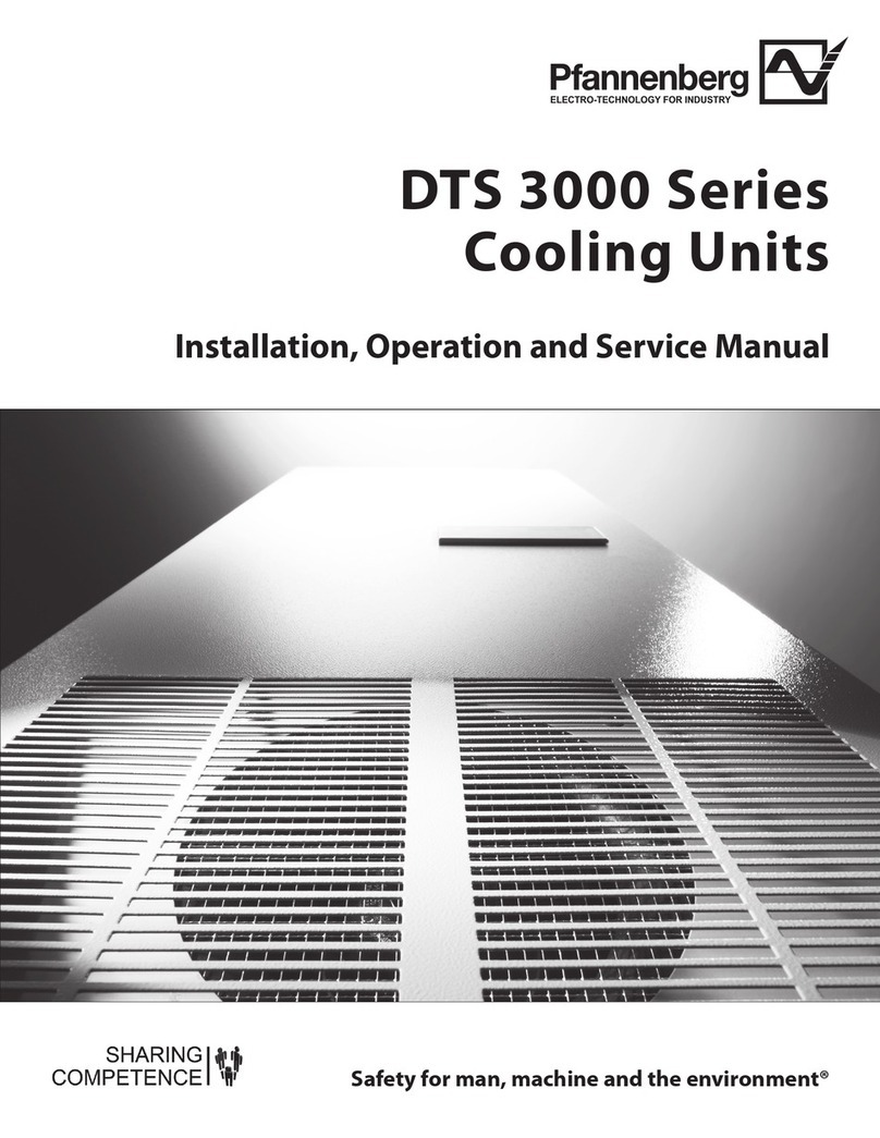
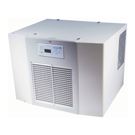
  9. Pfannenberg DTS 3241 User manual

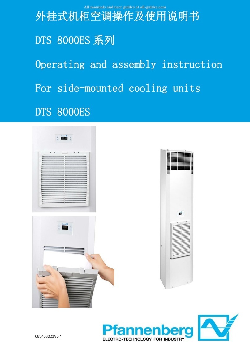
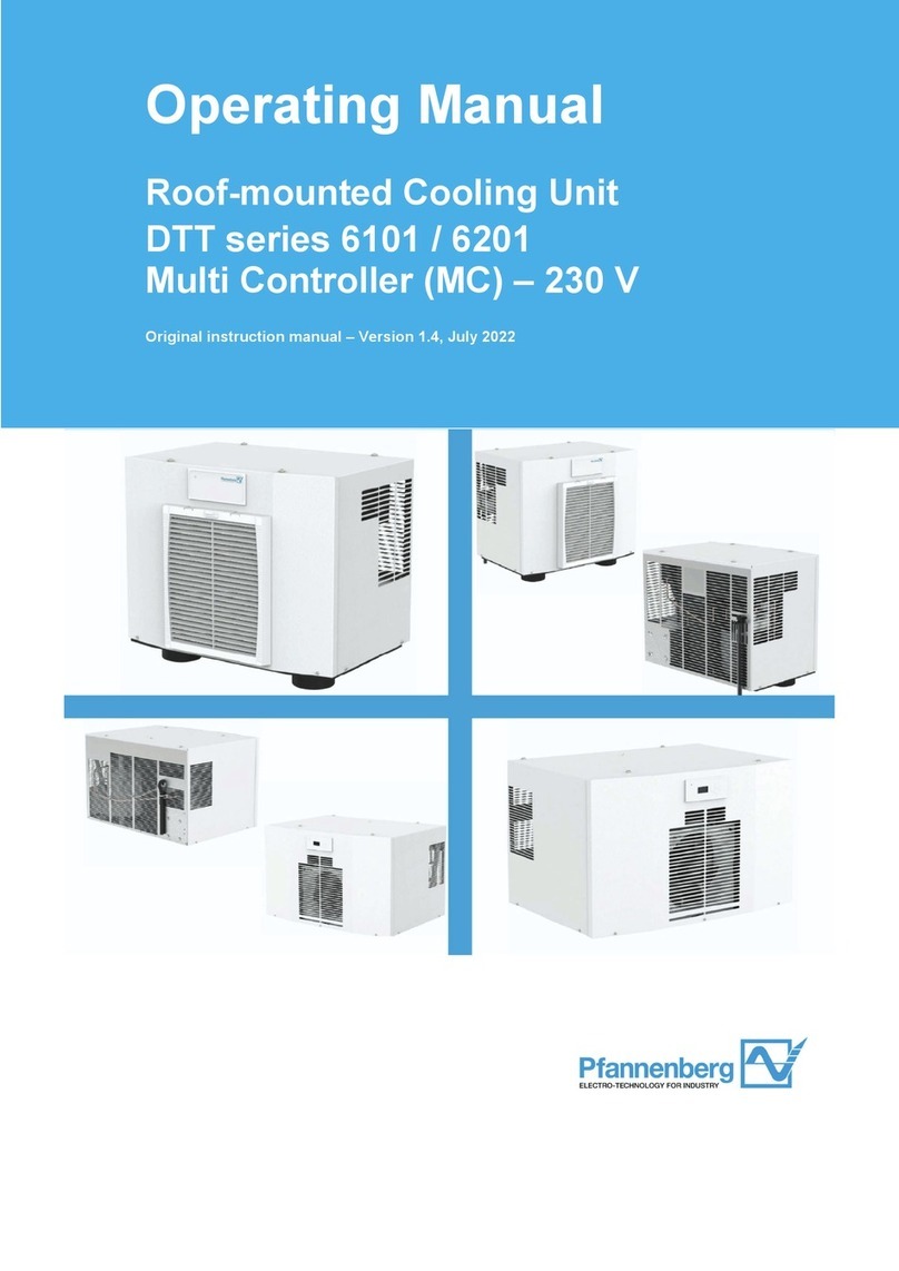
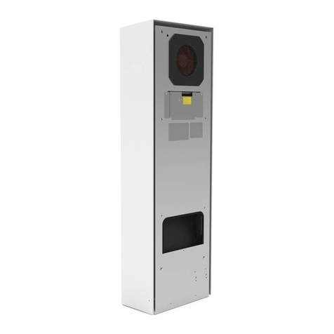
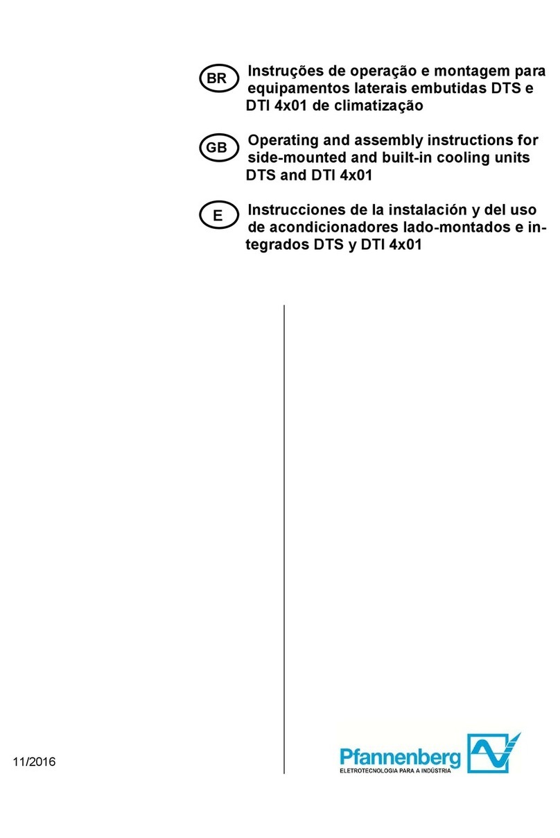
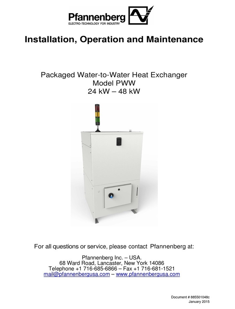
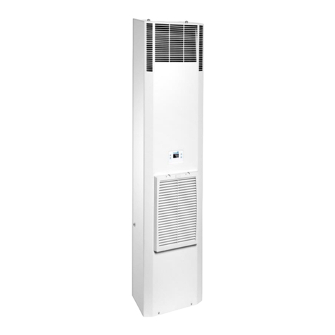
Pfannenberg DTS 3241 User manual

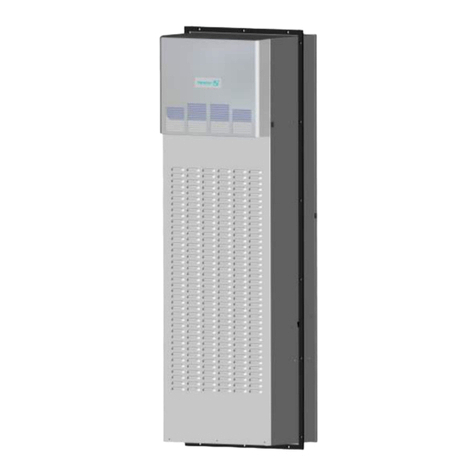
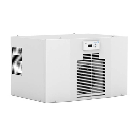
DTS 3241, 3261, and 3281
Indoor and Outdoor Cooling Units
Unpacking:
Prior to and during unpacking make a visual inspection of the cooling unit
to see whether any damage has occurred during transportation.
Pay special attention to loose parts, dents, scratches, visible loss of oil etc.
Any damage must be reported immediately to the delivering carrier.
Save the carton and packaging material and request an inspection.
Then file a claim with the delivering carrier.
Before disposing of packaging material ensure that it does not contain any
loose components.
Danger!
Burrs caused by production may be present on the metal edges of the
unit. Always wear protective gloves when carrying out maintenance
work and installation. In case of a warranty claim, exact details on the
fault (photograph, if possible); the unit part number and serial number
of the cooling unit are required.
885408002
Pfannenberg Inc.
Subsidiary of the Pfannenberg Group
68 Ward Road—Lancaster, NY 14086
Phone: (716) 685-6866—Fax: (716) 681-1521
www.pfannenbergusa.com
Warranty Conditions:
(WARRANTY IS VALID FOR 1 YEAR)
Warranty becomes null and void:
In case of improper usage of the unit, noncompliance with operating conditions
or nonobservance of instructions.
If operated in rooms in which corrosives or acids are present in the atmosphere.
In case of damage caused by contaminated or jammed air filters.
If a non-authorized person interrupts the cooling circulation, modifies the unit or
changes the serial number.
In case of damage caused by transport or by accidents.
For the exchange of parts by non-authorized companies.
In order to maintain your warranty rights please observe the following when
returning the unit.
Enclose an exact description of the fault in the shipping package.
Enclose proof of delivery (delivery note or copy of invoice).
Return the unit together with all accessories; use the original packaging or
packaging of equivalent quality, send the unit freight prepaid and covered by an
adequate transport insurance.
Safety:
Cooling units produced by Pfannenberg are designed for dissipating heat from
switch cabinets. During each cooling process condensate can be produced.
The cooling unit may only be used under the ambient conditions specified on
the enclosed sheet.
The cooling unit is to a large measure maintenance-free, (See Maintenance
Section)
Every other use is considered as non-authorized use making any warranty null
and void.
The electrical equipment must be regularly checked. Any faults such as loose
connections or scorched cable must be removed immediately.
Work on the cooling system and on electrical components may only be carried
out by authorized specialist personnel.
Compliance with applicable safety and environmental regulation is mandatory.
Cleaning and Maintenance:
The cleaning intervals depend upon the relevant operating condi-
tions. In particular, observe the following instructions:
Clean the heat exchanger regularly.
Clean the heat exchanger using a soft brush or pressurized air.
It is recommended that the condensate run off opening be checked
regularly.
If the cooling units are provided with a filter, clean the filter mat regularly.
The cleaning intervals or the intervals for replacement of the filter mat
mainly depends upon ambient conditions (air quality.)
You can rinse the filter mat using water heated to 40 C and commercially
available mild detergent.
It is possible to remove any dirt by knocking the mat slightly, vacuum clean-
ing it or blowing it out.
If the filter mat is oily or greasy, please replace.
Caution!
Protect the electric components against leakage.
Do not use any pointed of sharp-edged objects. The ribs should not be
compressed or damaged during the cleaning process.
If the covering hood is removed, the electric plug-in connections on the
inside must be removed by hand. During fitting do not forget to plug-in!
Fault Possible Cause Remedy
Unit fails to
cool. Internal
fan is running.
Temperature setting to high.
Check temperature setting.
Unit fails
to cool
sufficiently.
Required cooling
capacity exceeds capacity of
unit.
Dirty filter or condenser.
Lack of refrigerant.
Internal and external fans not
working.
Air not circulating properly
inside the switch cabinet.
Check ambient temperature and
internal load.
Clean condenser. Clean or replace
filter.
Call authorized technician. Check
unit for leaks.
Call authorized technician. Check
fan capacitors. Replace fans.
Check enclosure and air circula-
tion inside enclosure. Air intake
and exhaust must be unimpeded
by components.
Condensate
accumulates
in switch
cabinet.
Exiting temperature is too
low. Enclosure is not suffi-
ciently sealed.
Set cooling unit to a higher tem-
perature setting. Close enclosure
door and improve the seal in the
enclosure.
Condensate
fails to drain. Condensate drain is clogged. Clean condensate drainage.
Condensate drainage hose must
be inclined downward without
showing a bend.
Indication
Faults LED:
Door Contact
High Pressure
Start Up
*C = Off, CF = Off, EF = Off
*C = Off, CF = Off, EF = On
*C = On, CF = On, EF = On
**Sequence: 1, (Contacts Closed)
***Sequence: 2, (Contacts Open)
****Sequence: 3, (Contacts Open)
Sequence 1: (User Error)
Sequence 2: (Unit Fault)
Sequence 3: (Test/start-up mode)
*C = Compressor; CF = Condenser Fan; EF = Evaporator Fan
General Information:
Installation:
When tightening the bolts the gasket should be evenly compressed half the
thickness of the gasket.
Over compression of the gasket will not provide a better seal to the enclosure.
MAKE SURE NOTHING IS MOUNTED 6 INCHES IN FRONT OF INLET FAN.
CAUTION!
If the cooling unit is mounted on a switch cabinet door, it must be confirmed that the
hinge can support the additional weight or that the switch cabinet will not topple over
when the door is opened.
CAUTION!
Make cutouts required to the enclosure prior to mounting the air conditioner. Make
sure that metal particles are not allowed to enter the enclosure.
Electrical Connection:
All power connections and repairs should be carried out by an authorized
trained electrician.
No other equipment should be connected to this circuit to prevent overloading.
Both main voltage and frequency must correspond to the nominal values indi-
cated on the nameplate of the cooling units.
ATTENTION!
THE COOLING UNIT MAY BE DAMAGED IF THE VOLTAGE IS TOO HIGH.
Testing and Startup Procedure:
Operating Conditions:
Door Contact: (All Units)
To avoid an increased production of condensate and for safety reasons a
door limit switch should be connected to the terminals provided
(see circuit diagram, housing cover or supplement.)
Centralized Fault Indication:
The signal of a fault in the cooling unit is caused by the high pressure
switch being opened.
This fault is displayed by the breaking of a potential-free contact.
Therefore, if the fault wire breaks, a fault signal will be simulated.
WARNING!
THE CONTACTS MAY BE LOADED WITH MAX. 230V, 10A.
Minimum Circuit Protection Class CC
NAME PLATE
125% of Run Load Amps
Short Circuit Protection for:
115/230V: 1000 Amps; 400/460V: 5000 Amps
Hz
+ / - 3Hz+ / - 10%
Handling:
Storage:
Failure to observe these instructions will render the warranty provisions null and void.
If it is necessary to store the air conditioner in a horizontal position prior to mounting,
make sure that it is placed in a vertical position for a minimum of 1 hour prior to
starting the unit.
Running the compressor without oil in the compressor will cause permanent damage
to the air conditioner, and void the warranty of the unit.
TEST THE UNIT FOR FUNCTIONALITY PRIOR TO MOUNTING THE
AIR CONDITIONER ON THE ENCLOSURE.
Terminal Connections:
Ground
Neutral
Power
Permanent Connection Detail
[Drilling Template Available on http://www.pfannenbergusa.com]
Mounting Insulation Installation:
Side Iso—Side Iso must be applied
on mounting holes on left and right
sides.
Top Iso—Ensure notch and groove
match sides.
Must extend to side Iso; mid and
bottom of unit.
Door Contact
Electrical Connection
When unit is plugged in, the drawn-in switch cabinet internal air tempera-
ture is measured by a temperature sensor.
If the compressor and condenser fan do not turn on, adjust the thermostat
down to a lower setting that will call for the compressor and condenser
fan.
You should feel a temperature difference between the inlet and outlet air.
325mm
[12 13/16”]
WITH RAIN HOOD
DTS 3261 & DTS 3281
269mm
[10 5/8”]
WITHOUT RAIN HOOD
DTS 3241 395mm
[15 9/16”]
1208mm
[47 9/16”]
Technical Information: 115 Volt 60 Hz
Amp Draw: 15.9 Amps
Capacity (95F/95F)[35C/35C]: 3241/61/81: 6825 BTUH [2000 W]
Capacity (122F/95F)[50C/35C]: 3241/61/81: 6313 BTUH [1850 W]
3241:54kg [119lbs]; 3261:56kg [123.5lbs]; 3281:60kg [132.2lbs]Weight:
Technical Information: 230 Volt 50/60 Hz
Amp Draw: 6.2 Amps
Capacity (95F/95F)[35C/35C]: 3241/61/81: 6825 BTUH [2000 W]
Capacity (122F/95F)[50C/35C]: 3241/61/81: 6313 BTUH [1850 W]
3241:54kg [119lbs]; 3261:56kg [123.5lbs]; 3281:60kg [132.2lbs]Weight:
Technical Information: 400/460 Volt 50/60 Hz
Amp Draw: 3.5 / 3.0 Amps
Capacity (95F/95F)[35C/35C]: 3241/61/81: 6825 BTUH [2000 W]
Capacity (122F/95F)[50C/35C]: 3241/61/81: 6313 BTUH [1850 W]
3241:61kg [135lbs]; 3261:63kg [139lbs]; 3281:67kg [147lbs]Weight:

This manual suits for next models

2

Other Pfannenberg Accessories manuals

Pfannenberg DTS 6201C User manual

Pfannenberg

Pfannenberg DTS 6201C User manual

Pfannenberg DTS 8000ES Product guide

Pfannenberg

Pfannenberg DTS 8000ES Product guide

Pfannenberg DTI 9441 Manual

Pfannenberg

Pfannenberg DTI 9441 Manual

Pfannenberg DTI 8665 Product guide

Pfannenberg

Pfannenberg DTI 8665 Product guide

Pfannenberg DTT 6x01 Product guide

Pfannenberg

Pfannenberg DTT 6x01 Product guide

Pfannenberg DTS 3641 User manual

Pfannenberg

Pfannenberg DTS 3641 User manual

Pfannenberg DTT Series User manual

Pfannenberg

Pfannenberg DTT Series User manual

Pfannenberg DTS series User manual

Pfannenberg

Pfannenberg DTS series User manual

Pfannenberg DTS 4x01 Series Product guide

Pfannenberg

Pfannenberg DTS 4x01 Series Product guide

Pfannenberg DTS series Product guide

Pfannenberg

Pfannenberg DTS series Product guide

Pfannenberg PWW 3482 Installation and operating instructions

Pfannenberg

Pfannenberg PWW 3482 Installation and operating instructions

Pfannenberg DTS 3000 Series Setup guide

Pfannenberg

Pfannenberg DTS 3000 Series Setup guide

Pfannenberg DTT 6 01 Series Product guide

Pfannenberg

Pfannenberg DTT 6 01 Series Product guide

Pfannenberg DTS 6301C User manual

Pfannenberg

Pfannenberg DTS 6301C User manual

Pfannenberg DTS series User manual

Pfannenberg

Pfannenberg DTS series User manual

Pfannenberg DTS series Product guide

Pfannenberg

Pfannenberg DTS series Product guide

Pfannenberg DTI 8000ES Product guide

Pfannenberg

Pfannenberg DTI 8000ES Product guide

Popular Accessories manuals by other brands

Sunx DP4 Series instruction manual

Sunx

Sunx DP4 Series instruction manual

Philips SVC2340/10 Instructions for use

Philips

Philips SVC2340/10 Instructions for use

Purize Sanibox user guide

Purize

Purize Sanibox user guide

Baumer R600V.DAH5 operating manual

Baumer

Baumer R600V.DAH5 operating manual

TP-Link TL-PBG13400 manual

TP-Link

TP-Link TL-PBG13400 manual

Simrad PI50 -  REV A Installation

Simrad

Simrad PI50 - REV A Installation

AEG DB 70 Instructions for use

AEG

AEG DB 70 Instructions for use

Hydac CS 1x10-A-0-0-0-1/-000 Quick start manual

Hydac

Hydac CS 1x10-A-0-0-0-1/-000 Quick start manual

Dometic OASIS ELITE 975 Series Installation & operating instructions

Dometic

Dometic OASIS ELITE 975 Series Installation & operating instructions

Panasonic Band Switching Diodes MA27077G specification

Panasonic

Panasonic Band Switching Diodes MA27077G specification

Cybermind Visette45 Operation manual

Cybermind

Cybermind Visette45 Operation manual

Lascar EasyLog EL-WiFi quick start guide

Lascar

Lascar EasyLog EL-WiFi quick start guide

TEKTELIC Communications T0004437 user manual

TEKTELIC Communications

TEKTELIC Communications T0004437 user manual

PCB Piezotronics M261B01 Installation and operating manual

PCB Piezotronics

PCB Piezotronics M261B01 Installation and operating manual

H-L Data Storage HLT-SDBF1 Specifications

H-L Data Storage

H-L Data Storage HLT-SDBF1 Specifications

Teqball SMART Series owner's manual

Teqball

Teqball SMART Series owner's manual

Panasonic HL-C211BE instruction manual

Panasonic

Panasonic HL-C211BE instruction manual

WIKA SENSeOR AMS01 user manual

WIKA

WIKA SENSeOR AMS01 user manual

manuals.online logo
manuals.online logoBrands
  • About & Mission
  • Contact us
  • Privacy Policy
  • Terms and Conditions

Copyright 2025 Manuals.Online. All Rights Reserved.